
Related Manuals for LEGRAND 430 557


Summary of Contents for LEGRAND 430 557
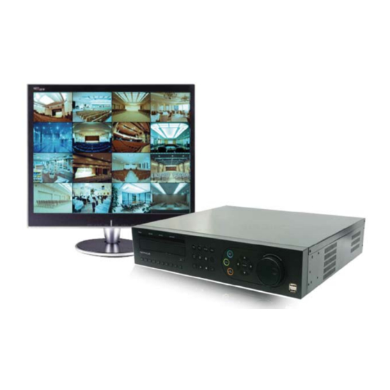
- Page 1 • 4/8/16-camera 500 GB LAN recorder with centralized management on PC 430 557/558/559 430 557 430 558 - 430 559 Manuale di istruzioni USER MANUAL User manual...
-
Page 2: Table Of Contents
TABLE OF CONTENTS Product Informations ................3 Features ......................... 4 System design ......................... 4 General specifications ....................... 5 Front case button description - 391509 ................6 Rear panel I/O description - 391509 .................. 6 Front case button description - 391510 - 391511 .............. 7 Rear panel I/O description - 391510 - 391511 .............. -
Page 3: Product Informations
PRODUCT INFORMATIONS Glossary PTZ : Pan / Tilt / Zoom PIP : Picture in Picture Water Mark : recording files with watermarking applied can be checked to verify they would not have been altered or edited. -
Page 4: Features
Before carrying out the installation, read the instructions and take account of the product’s specific mounting location. Do not open up the device. All Legrand roducts must be opened and repaired only by personnel trained and approved by Legrand. Any unauthorised opening or repair completely cancels all liabilities and the rights to replacement and guarentees. -
Page 5: General Specifications
• General specifications • Advanced hardware MPEG 4 • Embedded O/S ROM • Up to 16 Camera input 4/8/16 • Auto-sequence screen division and PIP/POP function • Real time display • Recording : PAL • 4 CH audio recording and two way audio communication •... -
Page 6: Front Case Button Description 391509
• Front case button description 391509 391511 button Records images PTZ. button Operates Pan/Tilt camera division button 1ch,4ch division button LED Indicator Indicate present system status information Move button Moves to setup and menu. Operates PTZ camera Enter Button Play forward button CD-ROM USB Port: 2 PORT... -
Page 7: Front Case Button Description - 391510 - 391511
• Front case button description 391511 SEQ. button Function button Division rotating surveillance button Setup Status, Audio, Backup, P/T/Z, SEQ, Log list SPOT button Menu button Shows the menu, moves to upper menus and complete setup Setup SPOT monitor LED Indicator PTZ. -
Page 8: Remote Controller Button Description
• Remote controller button description 391509 - 391510 - 391511... -
Page 9: Installation
INSTALLATION... -
Page 10: System Setup
SYSTEM SET UP • POWER ON/OFF switch [R5] O (O ) /1 (On) • Power on Connect the power cable then press the power switch [R5] to be “ON”. • Power off Select “SHUTDOWN” [M1.7.7]. Select “ENTER/OK” button after the message “ System will shutdown ! ”. Press the power switch [R5] to be off. -
Page 11: Screen Display
• SCREEN DISPLAY... -
Page 12: Before Setting Up System
• BEFORE SETTING UP SYSTEM Input password • Select the “LOGIN ID” and input the corresponding password using number buttons – [F18] or [RC3] or KeyPad - at the password box. How to use Menu • Move menu cursor using arrow buttons [F8] or [RC10]. •... - Page 13 Text input box • Click on letters or select letters/symbols using arrow buttons -[F8] or [RC10]- then press “ENTER/OK” button -[F9] or [RC11]- ; the selected letters/symbols will appear on the top text box. “CAP” is used to toggle keyboard upper/lower case. Moving to the next menu page Press button to move to the next menu page when...
- Page 14 Menu Tree Structure MENU SETUP DISPLAY CAMERA RECORD EVENT STORAGE NETWORK SYSTEM [M1.1] [M1.2] [M1.3] [M1.4] [M1.5] [M1.6] [M1.7] OSD [M1.1.1] GENERAL PROPERTY MOTION HDD FORMAT SETUP CONFIG LIVE-SEQ(FULL) PTZ [M1.2.2] SCHEDULE SENSOR AUTO-BACKUP DDNS TIME LIVE-SEQ(QUAD) * PRESET MISC [M1.3.3] VLOSS CLIENT SOFTWARE...
-
Page 15: System Login
• SYSTEM LOGIN Starting system menu Press “MENU” button – [F7] or [RC5] - or click on “MENU”. Input administrator’s password on the password box. ¢— The default “ADMIN” value is 0000. (“SETUP” rights are required. They are granted to Administrator. They can be granted to other users (cf. -
Page 16: Setting Up Screen Display [M1.1]
• SETTING UP SCREEN DISPLAY [M1.1] Screen display setup – On Screen Display (OSD) [M1.1.1] • Status name the name of each camera (cf M1.2.1) is displayed and recorded (ON/OFF) • Camera number the number of each channel is displayed (ON/OFF) •... - Page 17 Screen display setup – live sequence scanning (full screen) [M1.1.2] Setup duration time for live sequence scanning in full screen. maximum input : 99 seconds RENVOI p19 Screen display setup – live sequence scanning (quad screen) (only for 8/16 CH pro- ducts) [M1.1.3] Setup duration time for live sequence scanning in quad screen.
- Page 18 Screen display setup – spot sequence scanning (full screen) _ (only for 8ch/16ch products) Setup duration time for spot sequence scanning in full screen (maximum 99 s). Screen display setup – spot sequence scanning (quad screen) [M1.1.5] Setup duration time for spot sequence scanning in quad screen (maximum 99 s) Quad screen number camera Camera 1 ~ Camera 4...
- Page 19 Screen display setup – miscellaneous [M1.1.6] Deinterlace (on/off) prevent screen twittering during playback of image which is recorded in low frame rate and 720X480 or 720X576 resolution. VGA resolution 600 x 800 / 1024 x 768 / 1280 x 1024 Video type Auto Detect / jumper / NTSC / PAL Keep PAL video type...
-
Page 20: Camera Setup [M1.2]
• CAMERA SETUP [M1.2] Camera setup – general [M1.2.1] [M1.1.4] TITLE : input camera/channel (CH) names. It can be displayed (or not) on the monitor (cf M1.1.1). COVERT : show or hide channels (ON/OFF) AUDIO : select connected audio channels [R3]. Camera setup –... - Page 21 Camera setup – preset [M1.2.3] System will record according to preset camera positions. Check if the camera supports preset function before setting up. Up to 64 preset positions for each channel. CAMERA : select cameras to setup preset positions. PAGE : move to the next page. SET : To enter PTZ mode and define PTZ CLE : Clear the recorded position CLEAR ALL : clear all the setup values for the camera selected.
- Page 22 Camera setup – TOUR [1.2.4] You can move camera to follow a path by saved preset positions for each channel. You can set 4 scan point lists for each channel. CAMERA : select a camera to set scan point. LIST : select a list to save scan point. You can setup total 4 lists.
- Page 23 Camera setup – COLOUR [M1.2.5] CAMERA : select a camera. BRIGHT : adjust color brightness. CONTRAST : adjust color contrast. COLOR : adjust camera color DEFAULT : set it as default value. Camera setup – position [M1.2.6] CAMERA : select a camera RIGHT/LEFT : move the camera to right and left.
-
Page 24: Record Setup [M1.3]
• RECORD SETUP [M1.3] Record setup – Property [M1.3.1] To set up the resolution of the recorded pictures (according to the schedule parameters set up in following page), for each channel, and : • quality in normal mode • quality when event occurs. •... - Page 25 RECORDING TIME LAPSE (high quality) RECORDING TIME LAPSE ( high quality ) RECORDING TIME LAPSE ( high quality ) GB Hard Disk GB Hard Disk Unit: Hour Unit: Hour Recording Recording Picture Quality (KB) Picture Quality (KB) Speed Speed HALF D1 (FPS) HALF D1 (FPS)
- Page 26 RECORDING TIME LAPSE (high quality) 1000 GB Hard Disk Unit: Hour Picture Quality (KB) Recording 1000 GB Hard Disk Unit: Hour Speed HALF D1 (FPS) Picture Quality (KB) Recording Normal High Best Normal High Best Normal High Best Speed HALF D1 (FPS) Normal High...
- Page 27 Record setup – schedule [M1.3.2] System records according to set schedule. (1) Select a channel to set up schedule. (2) Select day/time to record and press “ENTER/OK” button [F9] or [RC11]. It shifts to a different type (C/E/I/_) as you press “ENTER/OK” button. The recording’s parameters of normal mode and intense mode are defined in previous page “RECORD/SET UP”...
- Page 28 Record setup – miscellaneous [M1.3.3] OVERWRITE : erase previous video data and record over it when HDD is full. AUTO-DELETE : automatically delete data after set date. CONTINUOUS REC : you cannot stop recording while it is in process as it continuously records. WATER-MARK : activate watermarking function.
-
Page 29: Event Setup [M1.4]
• EVENT SETUP [M1.4] • NOTE : you have to set it as “Event recording” at Schedule record setup to use this function. When the event (sensor/motion/video loss) is detected on DVR side, DVR alerts by message pop-up, beep sound or E-mail notification. - Page 30 Event setup – sensor [M1.4.2] RECORD : select camera to record on sensor detection TYPE : select sensor type (NO/NC) ALARM OUT : alarm port(s) activated on sensor detection Event setup – VLOSS (Video Loss) [M1.4.3] ALARM-OUT : select alarm port. NONE: disable alarm out.
- Page 31 Event setup – E-MAIL [M1.4.4] EVENT E-MAIL(ON/OFF) : select “ON” to enable the function MOTION(ON/OFF) : select “ON” Motion event detection SENSOR(ON/OFF) : select “ON” Sensor event detection VLOSS(ON/OFF) : select “ON” Video Loss event detection DVR NAME : input DVR name that will appeared on E-mail E-MAIL ADDRESS : input E-mail address (maximum 3) Note : when you apply this function on frequent motion detection or sensor detection, it will cause a lot of E-mail transmission, then it will affect to DVR system performance.
- Page 32 Event setup – MISC [M1.4.5] PRE-REC TIME : setup pre-recording time on the selected event detection. POST-REC TIME :setup post-recording time on the selected event detection. ALARM BUZZER : enable alarm buzzer on the selected event detection (On/OFF). ALARM OUT TIME : setup duration to activate alarm out on the selected event detection. EVENT POPUP : select “ON”...
-
Page 33: Storage [M1.5]
• STORAGE [M1.5] Storage – HDD format [M1.5.1] HDD can be formated. Select installed HDD and format. System will reboot after formatting is completed. Storage – AUTO-BACKUP [M1.5.2] AUTO-BACKUP – External USB TYPE storage is provided. You can thus backup data. TYPE : set operation types of AUTO-BACKUP . -
Page 34: Network [M1.6]
• NETWORK [M1.6] Network – setup [M1.6.1] • static – input static IP address and gateway, net mask. • DHCP – system automatically recognizes IP address. Do not use this type if the DVR is connected to a net-server. • PPPOE –... - Page 35 Network - DDNS [M1.6.2] NOTE : system supports free DDNS sites such as dyndns.com, ipupdater.com. SERVER : select registered server (OF/DYNDNS.com/NO-IP .com/IPUPDA- TER.com). SERVER-URL : indicate registered server URL USER ID : input ID registered to server. PASSWORD : input password registered to server. GROUP ID : input group ID registered to server.
- Page 36 Access list [M1.6.4] System can limit remote-PC, accessing network. Able to register Static IP and only remote-PC with registered IP can access system. NOTE : the system restricts all the other IPs, those are not registered if you once register an IP . If you want to ac- cess with all IP addresses, do not register any IP .
- Page 37 Server [M1.6.5] CC IP : input connection info of CAMS CC. PORT : input connection port of CAMS CC. (default value: 6500) CMM IP : input connection info of CAMS CMM. PORT input connection port of CAMS CMM. (default value:7600)
-
Page 38: System [M1.7]
• SYSTEM [M1.7] System – Configuration info [M1.7.1] The set values for menu can be saved to and load from USB storage. • Load configuration – loads saved configuration information. • Save configuration – save the values set in the current menu •... - Page 39 System – Time management [M1.7.2] • Current time – indicates current time of system. • Date format – select date format to display. classification display YY/MM/DD 2008/03/03 MM/DD/YY 03/03/2008 DD/MM/YY 03/03/2008 best Very good • Time format – select time format to display. classification display AM/PM...
- Page 40 • Time synchronization . When using TIME SYNC Function, please select “SNTP”. And then, System can automatically connects to internet time-server to check current time. • Server IP – input time-server IP address . Omit “www”. Select “ENTER/OK” -[F9] or [RC11]- and check if time-server works. example) time.kriss.re.kr ‡...
- Page 41 System – Miscellaneous [M1.7.4] SYSTEM-ID : input remote controller ID. KEYBOARD : control the system using keyboard controller (NONE, WONWOO, CHUBB, HI- SHARP). KEY-TONE : set buzzer sound on/off System – USER/Password management [M1.7.5] Can’t be changed Can’t be changed ADMIN password : change the administrator password.
- Page 42 System – System shutdown [M1.7.6] • Select “SYSTEM SHUTDOWN”. If you see the message “System will shutdown”, you can shutdown sy- stem.
-
Page 43: Basic Product Operation
BASIC PRODUCT OPERATION... -
Page 44: Mode (Screen Setup)
• MODE (Screen setup) • CLICK right Mouse button • Full screen mode ( or [F13] or [RC22]) Shifts to next channel each time you press these buttons. If you press a channel number button on remote-controller – [RC3] -, it turns full screen. •... - Page 45 • 9 division screen mode ( or [F13] or [RC25] _only for 8ch/16ch products) ??? • 16 division screen mode ( or [F13] or [RC24] _only for 16ch product) • POP screen mode ( or [RC20] _only for 8ch/16ch products) Press “POP”...
- Page 46 • PIP screen mode (Picture In Picture) You can monitor 2 screens at the same time with small screen inside of one screen by pressing “PIP” button [RC19]. Press “PIP” button so that the display channels will be exchanged. "PIP" Button "PIP"...
- Page 47 • SPOT screen (only for 8/16CH) Display real time screen of another screen-mode in different monitor using “SPOT OUT” port [R14]. “FUNCTION” button [F6] and select “SPOT” or [RC18] to set up “SPOT” screen. (1) type • single channel • playback only one selected channel in full screen mode.
-
Page 48: Sequence (Function) [M6.2] [F5] [Rc21]
• SEQUENCE (FUNCTION) [M6.2] [F5] Show each channel sequentially. The duration’s parameters are set on screen display menu [M1.1.4]. • Digital zoom Press “ZOOM” button in full screen mode to active digital zoom press “ZOOM” button [RC7]. zoomed area moves as you press arrow buttons - [F10] or [RC10] - or where you click. size of zoomed area gets bigger and smaller every time you press “ZOOM”... -
Page 49: Ptz (Function) [M6.1]
• PTZ (FUNCTION) [M6.1] • PTZ operation Press “PTZ” button -[F3] or [RC6] or [M6.1] - to display in full screen and operate PTZ cameras. Press “ENTER/OK” button in PTZ mode, you will see “PTZ-ADVANC” menu. • PTZ general movement (1)Moves pan/tilt camera from up/ down and right/ left using arrow keys [F8] or [RC10]. -
Page 50: Spot (Function) Only 8/16Ch [M6.2]
• SPOT (FUNCTION) _only 8/16CH [M6.2] • SPOT operation Press “FUNCTION” button [F6], select “SPOT“ to setup. • SPOT OUT DISPLAY Note : Refer MENU/SETUP/DISPLAY [M1.1.4 et M1.1.5] to select Spot out channels. *Screen display setup – spot sequence scanning (full screen) *Screen display setup –... -
Page 51: Audio (Function) [M6.3]
• Audio (FUNCTION) [M6.3] • Turn on/ off audio. Note : you can only playback audio in full screen mode. Audio On : Turn on audio Mute : Turn off audio Audio channel selection is set up in [M1.2.1] • Log View (FUNCTION) [M6.4] •... -
Page 52: Remote Controller Id
• Remote –controller ID • Remote-controller ID One remote-controller can be used to operate several DVRs at one site. The remote-controller operate one DVR at a time according to the registered ID value. DVD ID DVD ID DVD ID DVD ID •... -
Page 53: Search - Back-Up - Record
SEARCH – BACK-UP - RECORD Recording (“REC. F” rights are required (cf. USER [M1.7.5]). Press “REC” button [F2] or [RC1] or click [M2] to start/end recording. -
Page 54: Search
• SEARCH (“REC.F” rights are required (cf. [M1.7.5]). Press “SEARCH” button -[F12] or [RC12] or [M3]- then you can see the Search menu shown below. 0000 0000 0000 • Search by time Input the date and time to search. Press “ENTER/OK” button [F9] or [RC11] or click “OK”. •... - Page 55 • Go to first playback from the beginning part of recorded. • Go to last playback from the recent part of recorded. • How to view covert-on (hidden) channel 0000 Select "SHOW HIDDEN CH". Click this icon, Or "Search" button at the front panel. Or "Search"...
-
Page 56: Backup
• Backup (“REC.F” rights are required (cf. [M1.7.5]). backup data using USB device. (1) Connect USB device to the DVR’s USB port [F11] (2) Press Function button [F6] and select “BACKUP” [M4] (3) Select options from menu. • (DEVICE – select the device to backup. •... - Page 57 Do not remove USB device during Backup ! Note: In case backup data file size is too small, then backup will be completed shortly without showing this progress window.
- Page 58 Backup viewer (1) open file : Load the backup data. (2) AVI: save the selected channel to avi during playback Select channel ‡ click this icon(start) ‡ click again(finish) (3) save : save the playback images as bmp file. (4) Print screen image (5) watermark : check if there is any modification of data.
- Page 59 • Open file (1) Click “OPEN FILE” button from the main screen. (2) Select files to playback. (3) Input backup password (4) After it completes to load the backup file, you can playback it, and save it as bmp files NOTE: 1) Both Admin and user can backup the data with this function.
- Page 60 • Audio playback (1) Load files with audio data. (2) Select and playback the channel, which audio is saved, it playbacks audio data at the same time. • Save (1) Save backup data. (2) Select screen division. (3) Click “SAVE” button. (4) Name the .bmp file and save.
- Page 61 • Watermark (1) Load files to check watermarking (2) Click “WATERMARK CHECK” button. (3) Click playback or speed playback button. (4) It shows the image with error message if there is any modification of data. It shows “ENTER/OK” in the status box if there is no modification of data.
-
Page 62: Cms Software
CMS SOFTWARE CMS (Central Management Software) can be used to manage up to 256 DVR. The CD supplied with the DVR contains the installation software and the user manuel in Instruction manual / CMS Folder. -
Page 63: General Specifications
SPECIFICATIONS Mode l N° 391 5 09 391 5 10 391 5 11 System Video Input 4 CH, B NC 8 CH, B NC 16 CH , BNC Output 1 CH, B NC SPOT Output 1CH BNC VG A Output 600x800, 1024x76 8, 128 0x1024 Input 4 CH RCA... -
Page 64: Web User
Web user • Web user : Remote monitoring available through internet explorer without the specific CMS software. • 36 Display Screens, Division screens, PTZ Controller supported. • Input IP or domain into the address field. • Install ActiveX file related to Web user. - Page 65 • Starting screen of connection • Click ‘Connect’ button to input each information and IP address for connection. Default : MSDVR Default : 1234 Default : 7621 Default : 7621 • Click ‘Connect’ button after input DVR Type, name, user’s ID, password, Site IP , port number etc.
Need help?
Do you have a question about the 430 557 and is the answer not in the manual?
Questions and answers