
Related Manuals for LEGRAND KEOR HPE 60 kVA


Summary of Contents for LEGRAND KEOR HPE 60 kVA
- Page 1 UPS OPERATING MANUAL MANUEL DE FONCTIONNEMENT DE L'ASI MANUALE OPERATIVO UPS KEOR HPE 60÷160 kVA...
- Page 2 ELECTROMAGNETIC COMPATIBILITY RISK OF DISTURBANCE This is a product for commercial and industrial application in the second environment - installation restrictions or additional measures may be needed to prevent disturbances. UPS category: C3 according to IEC 62040-2 COMPATIBILITE ELECTROMAGNETIQUE RISQUE DE PERTURBATIONS Ceci est un produit à...
- Page 4 UPS OPERATING MANUAL MANUEL DE FONCTIONNEMENT DE L'ASI MANUALE OPERATIVO UPS Index of sections / Indice delle sezioni Code/Codice 1 – WARNINGS AND GENERAL INFORMATION AVERTISSEMENTS ET INFORMATIONS GÉNÉRALES AVVERTENZE E INFORMAZIONI GENERALI OMB81275 2 – INSTALLATION AND START-UP INSTALLATION ET DÉMARRAGE DE L'ASI INSTALLAZIONE ED AVVIAMENTO OML46086 3 –...
-
Page 6: Table Of Contents
Warnings and general information Avertissements et informations générales Avvertenze e informazioni generali WARNINGS AND GENERAL INFORMATION AVERTISSEMENTS ET INFORMATIONS GÉNÉRALES AVVERTENZE E INFORMAZIONI GENERALI Index / Sommaire / Indice ENGLISH LANGUAGE ................3 CONVENTIONS USED ............... 4 DOCUMENTATION NOTES ............... 5 FACTORY WARRANTY .............. - Page 7 Warnings and general information Avertissements et informations générales Avvertenze e informazioni generali OMB81275 REV. B...
-
Page 8: English Language
Warnings and general information Avertissements et informations générales Avvertenze e informazioni generali ENGLISH LANGUAGE OMB81275 REV. B... -
Page 9: Conventions Used
Avertissements et informations générales Avvertenze e informazioni generali Thank you for choosing an Legrand product. This section of the manual contains indications regarding the symbols used in the UPS documentation as well as basic information about the product, including the factory warranty terms. -
Page 10: Documentation Notes
Warnings and general information Avertissements et informations générales Avvertenze e informazioni generali DOCUMENTATION NOTES Storing documentation This manual and any other supporting technical documentation relating to the product must be stored and made accessible to personnel in the immediate vicinity of the UPS. -
Page 11: Factory Warranty
Modes required a) In the event of a fault covered by the warranty, the customer shall notify Legrand in writing of the occurred fault, providing a short description of the fault. b) The customer shall also provide documents showing the validity of the warranty (receipt/purchasing invoice with serial number of the product –... - Page 12 Responsibility a) In no event shall Legrand be liable for direct or indirect damage, or any damage whatsoever connected with the execution of warranty services (e.g. possible voltage interruptions during the repair period or assembly and dismantling costs), except for the cases provided for by mandatory laws.
-
Page 13: Limitation Of Liability
LIMITATION OF LIABILITY All the information contained in the present documentation is the exclusive property of Legrand Written consent by Legrand is required in order to wholly or partially publish or disclose this information. The present manual constitutes an integral part of the product technical support documentation. -
Page 14: Langue Français
Warnings and general information Avertissements et informations générales Avvertenze e informazioni generali LANGUE FRANÇAIS OMB81275 REV. B... -
Page 15: Conventions Utilisees
Avertissements et informations générales Avvertenze e informazioni generali Merci d'avoir choisi un produit Legrand. Cette section du manuel contient des indications concernant les symboles utilisés dans la documentation UPS ainsi que des informations de base sur le produit, notamment les conditions de la garantie usine. -
Page 16: Remarques Relatives A La Documentation
Warnings and general information Avertissements et informations générales Avvertenze e informazioni generali REMARQUES RELATIVES A LA DOCUMENTATION Stockage de la documentation Ce manuel ainsi que les autres documentations techniques relatives à ce produit doivent être stockés et mis à disposition du personnel à proximité immédiate de l'UPS. -
Page 17: Garantie Usine
Documents requis a) Si le client constate un défaut couvert par la garantie, il doit en aviser Legrand par écrit en fournissant une brève description du défaut. b) Le client doit également fournir des documents prouvant la validité de la garantie (reçu/facture d'achat comportant le numéro de série du produit –... - Page 18 Responsabilité a) En aucun cas Legrand ne saurait être tenue responsable des dommages directs ou indirects, ou de tout autre dommage, quel qu'il soit, lié à l'exécution des services dans le cadre de la garantie (par ex. possibles interruptions de l'alimentation électrique pendant les réparations ou coûts d'assemblage et de démontage), excepté...
-
Page 19: Limitation De Responsabilité
LIMITATION DE RESPONSABILITÉ Toutes les informations contenues dans la présente documentation sont la propriété exclusive de Legrand. L'accord écrit de Legrand est requis pour toute communication ou publication totale ou partielle de ces informations. Le présent manuel constitue une partie intégrante de la documentation de support technique du produit. -
Page 20: Lingua Italiana
Warnings and general information Avertissements et informations générales Avvertenze e informazioni generali LINGUA ITALIANA OMB81275 REV. B... -
Page 21: Convenzioni Utilizzate
Avertissements et informations générales Avvertenze e informazioni generali Grazie per aver scelto un prodotto della Legrand. Questa sezione del manuale contiene indicazioni sulla simbologia utilizzata nella documentazione dell’UPS e informazioni di base sul prodotto, con l’inclusione delle condizioni di garanzia di fabbrica. -
Page 22: Note Sulla Documentazione
Warnings and general information Avertissements et informations générales Avvertenze e informazioni generali NOTE SULLA DOCUMENTAZIONE Conservazione della documentazione Questo manuale e tutta la restante documentazione tecnica di supporto al prodotto devono essere conservati, e possibilmente resi accessibili al personale nelle immediate vicinanze dell’UPS. -
Page 23: Garanzia Di Fabbrica
Modalità richieste a) In caso di guasto coperto da garanzia, il cliente dovrà informare per scritto la Legrand del guasto occorso, fornendo una breve descrizione del guasto stesso. - Page 24 Responsabilità a) Legrand non si assume nessuna responsabilità per danni di qualsiasi natura, diretti o indiretti, relativi alla esecuzioni delle prestazioni in garanzia (es. eventuali interruzioni di tensione durante il periodo di riparazione, eventuali costi di montaggio e smontaggio) salvo i casi previsti da inderogabili norme di legge.
-
Page 25: Limitazione Di Responsabilita
LIMITAZIONE DI RESPONSABILITA’ Tutte le informazioni contenute nella presente documentazione sono di esclusiva proprietà della Legrand Per la pubblicazione o la divulgazione integrale o parziale è necessario il consenso scritto della Legrand Il presente manuale costituisce parte integrante della documentazione tecnica di supporto del prodotto. - Page 26 Installation and start-up of KEOR HPE UPS 60÷160 kVA Installation et démarrage de l’ASI KEOR HPE 60÷160 kVA Installazione e avviamento KEOR HPE UPS 60÷160 kVA INSTALLATION AND START-UP OF KEOR HPE UPS 60÷160 KVA INSTALLATION ET DÉMARRAGE DE L’ASI KEOR HPE 60÷160 KVA INSTALLAZIONE E AVVIAMENTO UPS KEOR HPE 60÷160 KVA...
- Page 27 Installation and start-up of KEOR HPE UPS 60÷160 kVA Installation et démarrage de l’ASI KEOR HPE 60÷160 kVA Installazione e avviamento KEOR HPE UPS 60÷160 kVA Index / Indice ENGLISH LANGUAGE ..................9 SCOPE ..................... 11 SAFETY RULES AND WARNINGS ............12 USE OF THE UPS ......................
- Page 28 Installation and start-up of KEOR HPE UPS 60÷160 kVA Installation et démarrage de l’ASI KEOR HPE 60÷160 kVA Installazione e avviamento KEOR HPE UPS 60÷160 kVA 4.4.1 Battery connection and positioning ............... 37 4.4.1.1 7/9/11Ah 12V installation – KEOR HPE 60-80 kVA ..........38 4.4.1.2 12/14Ah 12V battery installation –...
- Page 29 Installation and start-up of KEOR HPE UPS 60÷160 kVA Installation et démarrage de l’ASI KEOR HPE 60÷160 kVA Installazione e avviamento KEOR HPE UPS 60÷160 kVA PROTECTION DE L'ENVIRONNEMENT ................63 2.4.1 Certification ISO 14001 .................... 63 2.4.2 Recyclage des matériaux d'emballage ..............63 2.4.3 Mise au rebut de l'appareil ..................
- Page 30 Installation and start-up of KEOR HPE UPS 60÷160 kVA Installation et démarrage de l’ASI KEOR HPE 60÷160 kVA Installazione e avviamento KEOR HPE UPS 60÷160 kVA DÉPANNAGE DE BASE ....................93 PROCEDURE D’ARRET ....................94 PROCÉDURE DE BASCULEMENT EN BY-PASS MANUEL ........... 95 REDEMARRAGE DEPUIS LE BY-PASS MANUEL ............
- Page 31 Installation and start-up of KEOR HPE UPS 60÷160 kVA Installation et démarrage de l’ASI KEOR HPE 60÷160 kVA Installazione e avviamento KEOR HPE UPS 60÷160 kVA MORSETTIERE ....................... 124 INSTALLAZIONE BATTERIE INTERNE ................ 125 4.4.1 Connessione batterie interne ................126 4.4.1.1 Installazione batterie 7/9/11Ah 12V –...
- Page 32 Installation and start-up of KEOR HPE UPS 60÷160 kVA Installation et démarrage de l’ASI KEOR HPE 60÷160 kVA Installazione e avviamento KEOR HPE UPS 60÷160 kVA Index of pictures / Indice delle figure Picture 1 – Rating plate of KEOR HPE 60÷160 kVA ..................13 Picture 2 –...
- Page 33 Installation and start-up of KEOR HPE UPS 60÷160 kVA Installation et démarrage de l’ASI KEOR HPE 60÷160 kVA Installazione e avviamento KEOR HPE UPS 60÷160 kVA Illustration 12- 7/9/11Ah 12V batterie connexion vue dessus ................83 Illustration 13- 7/9/11Ah 12V batterie connexion vue frontale ................83 Illustration 14 - Plateau 12/14Ah 12V vue latérale de la batterie ................
-
Page 34: English Language
Installation and start-up of KEOR HPE UPS 60÷160 kVA Installation et démarrage de l’ASI KEOR HPE 60÷160 kVA Installazione e avviamento KEOR HPE UPS 60÷160 kVA ENGLISH LANGUAGE OML46086 REV. I... - Page 35 Installation and start-up of KEOR HPE UPS 60÷160 kVA Installation et démarrage de l’ASI KEOR HPE 60÷160 kVA Installazione e avviamento KEOR HPE UPS 60÷160 kVA OML46086 REV. I...
-
Page 36: Scope
Installazione e avviamento KEOR HPE UPS 60÷160 kVA SCOPE The instructions contained in the operating manual are applicable to the UPS systems listed below. BSL46 KEOR HPE 60 kVA BSM46 KEOR HPE 80 kVA BSK93 KEOR HPE 100 kVA ... -
Page 37: Safety Rules And Warnings
SAFETY RULES AND WARNINGS USE OF THE UPS Congratulations on choosing a product from Legrand for the safety of your equipment. To obtain the best performance from your KEOR HPE 60÷160 kVA UPS system (Uninterruptible Power Supply), we suggest that you take your time to read the following manual. -
Page 38: Ups Rating Plate
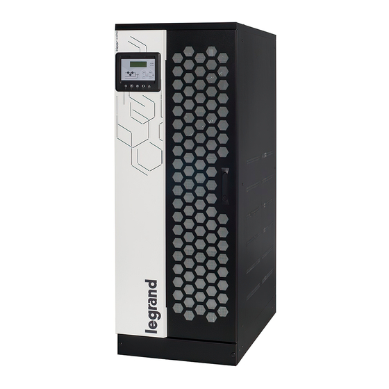
Installation and start-up of KEOR HPE UPS 60÷160 kVA Installation et démarrage de l’ASI KEOR HPE 60÷160 kVA Installazione e avviamento KEOR HPE UPS 60÷160 kVA UPS RATING PLATE The KEOR HPE UPS 60÷160 kVA is provided with an identification plate containing the operation ratings. -
Page 39: Special Safety Warnings
Installation and start-up of KEOR HPE UPS 60÷160 kVA Installation et démarrage de l’ASI KEOR HPE 60÷160 kVA Installazione e avviamento KEOR HPE UPS 60÷160 kVA SPECIAL SAFETY WARNINGS 2.3.1 General warnings The UPS is provided with various stickers with indications regarding specific dangers. These stickers must be always well visible and replaced in case they are damaged. -
Page 40: Installation
Installation and start-up of KEOR HPE UPS 60÷160 kVA Installation et démarrage de l’ASI KEOR HPE 60÷160 kVA Installazione e avviamento KEOR HPE UPS 60÷160 kVA 2.3.4 Installation The product must be installed in strict compliance with the instructions contained in the technical back-up documentation, including the present safety instructions. -
Page 41: Electrical Connection
Installation and start-up of KEOR HPE UPS 60÷160 kVA Installation et démarrage de l’ASI KEOR HPE 60÷160 kVA Installazione e avviamento KEOR HPE UPS 60÷160 kVA Do not modify the device Do not modify the device in any way: this may result in damage to the equipment itself as well as to objects and persons. -
Page 42: Operation
Installation and start-up of KEOR HPE UPS 60÷160 kVA Installation et démarrage de l’ASI KEOR HPE 60÷160 kVA Installazione e avviamento KEOR HPE UPS 60÷160 kVA Injury hazard due to electric shock! The device is subject to high voltages, thus all safety instructions must be scrupulously adhered to before performing any operation on the UPS: ... -
Page 43: Maintenance
Installation and start-up of KEOR HPE UPS 60÷160 kVA Installation et démarrage de l’ASI KEOR HPE 60÷160 kVA Installazione e avviamento KEOR HPE UPS 60÷160 kVA 2.3.7 Maintenance Service and repairs must be carried out by skilled and authorized personnel. Before carrying out any maintenance operation, the UPS must be disconnected from AC and DC supply sources. -
Page 44: Storage
ENVIRONMENTAL PROTECTION 2.4.1 ISO 14001 certification Legrand is particularly sensitive to the environmental impact of its products. That is why the UPS has been manufactured with cutting-edge eco-design criteria (ISO 14001 certification). Special care was taken in using fully recyclable materials and in reducing the amounts of raw materials used. -
Page 45: Installation
Installation and start-up of KEOR HPE UPS 60÷160 kVA Installation et démarrage de l’ASI KEOR HPE 60÷160 kVA Installazione e avviamento KEOR HPE UPS 60÷160 kVA INSTALLATION RECEIPT OF THE UPS Please inspect the device before installing it. In case any damage is noticed from the conditions of the package and/or from the outside appearance of the equipment, contact the shipping company or your dealer immediately. -
Page 46: Handling Of The Ups
Installation and start-up of KEOR HPE UPS 60÷160 kVA Installation et démarrage de l’ASI KEOR HPE 60÷160 kVA Installazione e avviamento KEOR HPE UPS 60÷160 kVA HANDLING OF THE UPS The UPS is packed on a pallet. It is handled from the transport vehicle to the installation (or storage) place via a fork lift. -
Page 47: Positioning And Installation
Installation and start-up of KEOR HPE UPS 60÷160 kVA Installation et démarrage de l’ASI KEOR HPE 60÷160 kVA Installazione e avviamento KEOR HPE UPS 60÷160 kVA POSITIONING AND INSTALLATION The KEOR HPE UPS 60÷160 kVA must be installed indoor, in a clean and dry room, preferably without dust or humidity infiltrations. -
Page 48: Base Plan, Static Load And Weights
Installation and start-up of KEOR HPE UPS 60÷160 kVA Installation et démarrage de l’ASI KEOR HPE 60÷160 kVA Installazione e avviamento KEOR HPE UPS 60÷160 kVA 3.3.1 Base plan, static load and weights Picture 3 – Base plan The supporting base of the UPS must be designed to carry the UPS weight and to ensure its steady and safe support. -
Page 49: Overall Dimensions, Clearances And Ventilation
Installation and start-up of KEOR HPE UPS 60÷160 kVA Installation et démarrage de l’ASI KEOR HPE 60÷160 kVA Installazione e avviamento KEOR HPE UPS 60÷160 kVA 3.3.2 Overall dimensions, clearances and ventilation OUTLET AIR OPENINGS INLET AIR OPENINGS Picture 4 – Overall dimensions Picture 5 –... - Page 50 Installation and start-up of KEOR HPE UPS 60÷160 kVA Installation et démarrage de l’ASI KEOR HPE 60÷160 kVA Installazione e avviamento KEOR HPE UPS 60÷160 kVA The UPS must be so installed as to ensure its serviceability and to allow a correct air flow as much as possible.
-
Page 51: Environmental Installation Conditions
Installation and start-up of KEOR HPE UPS 60÷160 kVA Installation et démarrage de l’ASI KEOR HPE 60÷160 kVA Installazione e avviamento KEOR HPE UPS 60÷160 kVA 3.3.3 Environmental installation conditions The air is classified by the EN 60721-3-3 standard (Classification of environmental parameters and their severities –... - Page 52 Installation and start-up of KEOR HPE UPS 60÷160 kVA Installation et démarrage de l’ASI KEOR HPE 60÷160 kVA Installazione e avviamento KEOR HPE UPS 60÷160 kVA Classification of chemically active substances (EN 60721-3-3) Class Environmental parameter 3C1R 3C1L Salt Salt Salt Sea salt...
-
Page 53: Positioning And Connection Of The Batteries
Installation and start-up of KEOR HPE UPS 60÷160 kVA Installation et démarrage de l’ASI KEOR HPE 60÷160 kVA Installazione e avviamento KEOR HPE UPS 60÷160 kVA POSITIONING AND CONNECTION OF THE BATTERIES Risk of electric shock A battery can present a risk for electrical shock and high short circuit current. The following precautions should be observed when working on batteries: Remove watches, rings or other metal objects;... -
Page 54: Electrical Connection
Installation and start-up of KEOR HPE UPS 60÷160 kVA Installation et démarrage de l’ASI KEOR HPE 60÷160 kVA Installazione e avviamento KEOR HPE UPS 60÷160 kVA ELECTRICAL CONNECTION The electrical connection is part of the work which is normally provided by the company that carries out the product installation. -
Page 55: Connection Of The Power Cables
Installation and start-up of KEOR HPE UPS 60÷160 kVA Installation et démarrage de l’ASI KEOR HPE 60÷160 kVA Installazione e avviamento KEOR HPE UPS 60÷160 kVA Mains connection The connection to the mains must be carried out with protection fuses between the mains and the UPS. - Page 56 Installation and start-up of KEOR HPE UPS 60÷160 kVA Installation et démarrage de l’ASI KEOR HPE 60÷160 kVA Installazione e avviamento KEOR HPE UPS 60÷160 kVA Details of the electrical connections Power (kVA) Input fuses [A] Rectifier Bypass Phase conductor cross sect. Rectifier 4x (1x50) 4x (1x70) 4x (1x95) 4x (1x95)
-
Page 57: Backfeed Protection Device
Installation and start-up of KEOR HPE UPS 60÷160 kVA Installation et démarrage de l’ASI KEOR HPE 60÷160 kVA Installazione e avviamento KEOR HPE UPS 60÷160 kVA BACKFEED PROTECTION DEVICE The KEOR HPE UPS is provided with voltage-free contacts which can be used to operate the shunt trip coil of the external sectioning device;... - Page 58 Installation and start-up of KEOR HPE UPS 60÷160 kVA Installation et démarrage de l’ASI KEOR HPE 60÷160 kVA Installazione e avviamento KEOR HPE UPS 60÷160 kVA Picture 6 – Single Line Diagram KEOR HPE 60-80kVA with connection to external device Picture 6a –...
- Page 59 Installation and start-up of KEOR HPE UPS 60÷160 kVA Installation et démarrage de l’ASI KEOR HPE 60÷160 kVA Installazione e avviamento KEOR HPE UPS 60÷160 kVA Picture 6b – Single Line Diagram KEOR HPE 125-160kVA with connection to external device OML46086 REV.
-
Page 60: Terminal Boards
Installation and start-up of KEOR HPE UPS 60÷160 kVA Installation et démarrage de l’ASI KEOR HPE 60÷160 kVA Installazione e avviamento KEOR HPE UPS 60÷160 kVA TERMINAL BOARDS The KEOR HPE UPS 60÷160 kVA is provided with terminal boards for the connection of power cables and of auxiliary connections. -
Page 61: Battery
Installation and start-up of KEOR HPE UPS 60÷160 kVA Installation et démarrage de l’ASI KEOR HPE 60÷160 kVA Installazione e avviamento KEOR HPE UPS 60÷160 kVA BATTERY CAUTION A battery can present a risk for electrical shock and high short circuit current. The following precautions should be observed when working on batteries: Remove watches, rings or other metal objects;... -
Page 62: Battery Connection And Positioning
Installation and start-up of KEOR HPE UPS 60÷160 kVA Installation et démarrage de l’ASI KEOR HPE 60÷160 kVA Installazione e avviamento KEOR HPE UPS 60÷160 kVA Internal batteries The UPS can have internal batteries. Servicing of batteries should performed by qualified personnel only. ... -
Page 63: 7/9/11Ah 12V Installation - Keor Hpe 60-80 Kva
Installation and start-up of KEOR HPE UPS 60÷160 kVA Installation et démarrage de l’ASI KEOR HPE 60÷160 kVA Installazione e avviamento KEOR HPE UPS 60÷160 kVA 4.4.1.1 7/9/11Ah 12V installation – KEOR HPE 60-80 kVA Remove the six screws to open the left/right lateral cover and access the battery trays (total trays are 6 and each contain three rows of 10 batteries, see picture 10 &... - Page 64 Installation and start-up of KEOR HPE UPS 60÷160 kVA Installation et démarrage de l’ASI KEOR HPE 60÷160 kVA Installazione e avviamento KEOR HPE UPS 60÷160 kVA 2) Install the batteries received in a separate packages and install it in accordance with the picture 12 and picture 13.
-
Page 65: 12/14Ah 12V Battery Installation - Keor Hpe 60-80 Kva
Installation and start-up of KEOR HPE UPS 60÷160 kVA Installation et démarrage de l’ASI KEOR HPE 60÷160 kVA Installazione e avviamento KEOR HPE UPS 60÷160 kVA 4.4.1.2 12/14Ah 12V battery installation – KEOR HPE 60-80 kVA Remove the six screws to open the left/right lateral cover and access the battery trays (total trays are 6 and each contain two rows of 7 batteries and one rows of 6 batteries, see picture 14 &... - Page 66 Installation and start-up of KEOR HPE UPS 60÷160 kVA Installation et démarrage de l’ASI KEOR HPE 60÷160 kVA Installazione e avviamento KEOR HPE UPS 60÷160 kVA Install the batteries received in a separate packages and install it in accordance with the picture 16 and picture 17.
-
Page 67: Connection Of The Auxiliary Cables
Installation and start-up of KEOR HPE UPS 60÷160 kVA Installation et démarrage de l’ASI KEOR HPE 60÷160 kVA Installazione e avviamento KEOR HPE UPS 60÷160 kVA CONNECTION OF THE AUXILIARY CABLES The UPS systems of the KEOR HPE 60÷160 kVA line can be connected to external controls/components specifically designed to improve the safety and reliability of the device. -
Page 68: Remote Emergency Power Off (Epo)
Installation and start-up of KEOR HPE UPS 60÷160 kVA Installation et démarrage de l’ASI KEOR HPE 60÷160 kVA Installazione e avviamento KEOR HPE UPS 60÷160 kVA 4.5.4 Remote emergency power off (EPO) Auxiliary EPO contact on terminals X10-7/8. The voltage supply to the loads can be interrupted from a remote location by using this contact (i.e. for safety requirements). -
Page 69: Serial Interfaces And External Connections
Installation and start-up of KEOR HPE UPS 60÷160 kVA Installation et démarrage de l’ASI KEOR HPE 60÷160 kVA Installazione e avviamento KEOR HPE UPS 60÷160 kVA SERIAL INTERFACES AND EXTERNAL CONNECTIONS The UPS is provided with serial interfaces and external connection facilities for the communication of the operating status and parameters. -
Page 70: Relay Card Connection (Optional)
Installation and start-up of KEOR HPE UPS 60÷160 kVA Installation et démarrage de l’ASI KEOR HPE 60÷160 kVA Installazione e avviamento KEOR HPE UPS 60÷160 kVA RELAY CARD CONNECTION (OPTIONAL) The KEOR HPE UPS 60÷160 kVA, in its full configuration, is provided with a relay card for repeating alarms and operating statuses remotely. -
Page 71: Startup And Shutdown
Installation and start-up of KEOR HPE UPS 60÷160 kVA Installation et démarrage de l’ASI KEOR HPE 60÷160 kVA Installazione e avviamento KEOR HPE UPS 60÷160 kVA STARTUP AND SHUTDOWN Read the technical documentation Before installing and using the device, make sure you have read and understood all the instructions contained in the present manual and in the technical supporting documentation. -
Page 72: Start-Up Procedure
Installation and start-up of KEOR HPE UPS 60÷160 kVA Installation et démarrage de l’ASI KEOR HPE 60÷160 kVA Installazione e avviamento KEOR HPE UPS 60÷160 kVA START-UP PROCEDURE EPO push-button and phase rotation Before switching the UPS on, make sure that: the emergency power off “EPO”... - Page 73 Installation and start-up of KEOR HPE UPS 60÷160 kVA Installation et démarrage de l’ASI KEOR HPE 60÷160 kVA Installazione e avviamento KEOR HPE UPS 60÷160 kVA INVERTER START UP The modulation of the inverter bridge is started. The AC output voltage reaches the PLEASE WAIT nominal value.
-
Page 74: Basic Troubleshooting
Installation and start-up of KEOR HPE UPS 60÷160 kVA Installation et démarrage de l’ASI KEOR HPE 60÷160 kVA Installazione e avviamento KEOR HPE UPS 60÷160 kVA BASIC TROUBLESHOOTING This paragraph provides the basic information if any problems occur during the start-up procedure. In case the problem cannot be solved, contact the service department. -
Page 75: Switching Procedure To Manual Bypass
Installation and start-up of KEOR HPE UPS 60÷160 kVA Installation et démarrage de l’ASI KEOR HPE 60÷160 kVA Installazione e avviamento KEOR HPE UPS 60÷160 kVA SWITCHING PROCEDURE TO MANUAL BYPASS The load is transferred to Manual Bypass with no interruption of supply to the loads. In this configuration, the system can be restarted via the return procedure from load on manual bypass, without the need to de-energize the loads. -
Page 76: Restart From Manual Bypass
Installation and start-up of KEOR HPE UPS 60÷160 kVA Installation et démarrage de l’ASI KEOR HPE 60÷160 kVA Installazione e avviamento KEOR HPE UPS 60÷160 kVA RESTART FROM MANUAL BYPASS Before restarting the UPS from manual by-pass, make sure the “Bypass_Sw" selector is in BYPASS position and the MBCB isolator is closed. - Page 77 Installation and start-up of KEOR HPE UPS 60÷160 kVA Installation et démarrage de l’ASI KEOR HPE 60÷160 kVA Installazione e avviamento KEOR HPE UPS 60÷160 kVA START UP FROM The load is transferred to the inverter. Move the selector MBCB Led #5 lit green.
-
Page 78: Langue Français
Installation and start-up of KEOR HPE UPS 60÷160 kVA Installation et démarrage de l’ASI KEOR HPE 60÷160 kVA Installazione e avviamento KEOR HPE UPS 60÷160 kVA LANGUE FRANÇAIS OML46086 REV. I... - Page 79 Installation and start-up of KEOR HPE UPS 60÷160 kVA Installation et démarrage de l’ASI KEOR HPE 60÷160 kVA Installazione e avviamento KEOR HPE UPS 60÷160 kVA OML46086 REV. I...
-
Page 80: Portee
PORTEE Les instructions contenues dans le présent manuel d'utilisation s'appliquent à l'ensemble de la gamme de systèmes ASI , telle qu'indiquée ci-dessous. BLS46 KEOR HPE 60 kVA BSM46 KEOR HPE 80 kVA BSK93 KEOR HPE 100 kVA ... -
Page 81: Règles De Securite Et Avertissements
Installation and start-up of KEOR HPE UPS 60÷160 kVA Installation et démarrage de l’ASI KEOR HPE 60÷160 kVA Installazione e avviamento KEOR HPE UPS 60÷160 kVA RÈGLES DE SECURITE ET AVERTISSEMENTS UTILISATION DE L'ASI Nous vous félicitons d'avoir choisi un produit pour la protection de vos équipements. Afin d'obtenir les meilleures performances de votre système ASI (alimentation secourue) KEOR HPE 60÷160, nous vous suggérons de lire attentivement le présent manuel. -
Page 82: Valeurs Nominales De L'asi
Installation and start-up of KEOR HPE UPS 60÷160 kVA Installation et démarrage de l’ASI KEOR HPE 60÷160 kVA Installazione e avviamento KEOR HPE UPS 60÷160 kVA VALEURS NOMINALES DE L’ASI L’ASI KEOR HPI 60÷160 kVA est fourni avec une plaque signalétique indiquant ses valeurs nominales de fonctionnement. -
Page 83: Avertissements Spécifiques Relatifs À La Sécurité
Installation and start-up of KEOR HPE UPS 60÷160 kVA Installation et démarrage de l’ASI KEOR HPE 60÷160 kVA Installazione e avviamento KEOR HPE UPS 60÷160 kVA AVERTISSEMENTS SPÉCIFIQUES RELATIFS À LA SÉCURITÉ 2.3.1 Avertissements généraux L'ASI est fourni avec diverses étiquettes autocollantes contenant des indications relatives à des dangers spécifiques. -
Page 84: Installation
Installation and start-up of KEOR HPE UPS 60÷160 kVA Installation et démarrage de l’ASI KEOR HPE 60÷160 kVA Installazione e avviamento KEOR HPE UPS 60÷160 kVA 2.3.4 Installation Le produit doit être installé conformément aux instructions contenues dans la documentation technique, dont font partie les présentes instructions de sécurité. -
Page 85: Raccordement Électrique
Installation and start-up of KEOR HPE UPS 60÷160 kVA Installation et démarrage de l’ASI KEOR HPE 60÷160 kVA Installazione e avviamento KEOR HPE UPS 60÷160 kVA Ne modifiez pas l'appareil Vous ne devez en aucun cas modifier l'appareil, au risque d'entraîner des dommages à l'équipement lui-même, ainsi qu'aux personnes et aux biens. -
Page 86: Fonctionnement
Installation and start-up of KEOR HPE UPS 60÷160 kVA Installation et démarrage de l’ASI KEOR HPE 60÷160 kVA Installazione e avviamento KEOR HPE UPS 60÷160 kVA Risques de blessure liés à un choc électrique ! L'appareil est soumis à des tensions élevées. Par conséquent, toutes les instructions de sécurité... -
Page 87: Maintenance
Installation and start-up of KEOR HPE UPS 60÷160 kVA Installation et démarrage de l’ASI KEOR HPE 60÷160 kVA Installazione e avviamento KEOR HPE UPS 60÷160 kVA 2.3.7 Maintenance L'entretien et les réparations doivent être réalisés par un personnel compétent et autorisé. Avant toute opération de maintenance, l'ASI doit être déconnecté... -
Page 88: Stockage
PROTECTION DE L'ENVIRONNEMENT 2.4.1 Certification ISO 14001 Legrand est particulièrement sensible à l'impact de ses produits sur l'environnement. C'est pourquoi l'ASI est fabriqué en tenant compte de critères d'éco-conception de pointe (certification ISO 14001). Une attention spéciale a été accordée à l'utilisation de matériaux entièrement recyclables et à la réduction des quantités de matières premières utilisées. -
Page 89: Installation
Installation and start-up of KEOR HPE UPS 60÷160 kVA Installation et démarrage de l’ASI KEOR HPE 60÷160 kVA Installazione e avviamento KEOR HPE UPS 60÷160 kVA INSTALLATION RECEPTION DE L'ASI Inspectez l'appareil avant de l'installer. Si vous constatez des dommages au niveau de l'emballage et/ou de l'aspect extérieur de l'équipement, contactez immédiatement le transporteur ou votre revendeur. -
Page 90: Manutention De L'asi
Installation and start-up of KEOR HPE UPS 60÷160 kVA Installation et démarrage de l’ASI KEOR HPE 60÷160 kVA Installazione e avviamento KEOR HPE UPS 60÷160 kVA MANUTENTION DE L'ASI L'ASI est emballé sur une palette. Il doit être déplacé du moyen de transport au site d'installation (ou de stockage) à... -
Page 91: Positionnement Et Installation
Installation and start-up of KEOR HPE UPS 60÷160 kVA Installation et démarrage de l’ASI KEOR HPE 60÷160 kVA Installazione e avviamento KEOR HPE UPS 60÷160 kVA POSITIONNEMENT ET INSTALLATION L'ASI KEOR HPE 60÷160 doit être installé à l'intérieur, dans une pièce propre et sèche, de préférence protégée de la poussière ou des infiltrations humides. -
Page 92: Plan De Base, Charge Statique Et Poids
Installation and start-up of KEOR HPE UPS 60÷160 kVA Installation et démarrage de l’ASI KEOR HPE 60÷160 kVA Installazione e avviamento KEOR HPE UPS 60÷160 kVA 3.3.1 Plan de base, charge statique et poids Plaque entrée câbles Illustration 3 – Plan de base Le sol soutenant l'ASI doit être conçue pour supporter le poids de l'ASI et assurer un maintien sûr et stable. -
Page 93: Dimensions Totales, Dégagement Minimum Et Ventilation
Installation and start-up of KEOR HPE UPS 60÷160 kVA Installation et démarrage de l’ASI KEOR HPE 60÷160 kVA Installazione e avviamento KEOR HPE UPS 60÷160 kVA 3.3.2 Dimensions totales, dégagement minimum et ventilation OVERTURES DE SORTIE D'AIR OVERTURES D'ENTRÉE D'AIR Illustration 4 –... - Page 94 Installation and start-up of KEOR HPE UPS 60÷160 kVA Installation et démarrage de l’ASI KEOR HPE 60÷160 kVA Installazione e avviamento KEOR HPE UPS 60÷160 kVA L'ASI doit être installé de manière à permettre son entretien et à assurer une circulation de l'air aussi correcte que possible.
-
Page 95: Conditions Environnementales D'installation
Installation and start-up of KEOR HPE UPS 60÷160 kVA Installation et démarrage de l’ASI KEOR HPE 60÷160 kVA Installazione e avviamento KEOR HPE UPS 60÷160 kVA 3.3.3 Conditions environnementales d'installation L'air est classifié par la norme EN 60721-3-3 (Classification des groupements des agents d'environnement et de leurs sévérités –... - Page 96 Installation and start-up of KEOR HPE UPS 60÷160 kVA Installation et démarrage de l’ASI KEOR HPE 60÷160 kVA Installazione e avviamento KEOR HPE UPS 60÷160 kVA Classification des substances chimiquement actives (EN 60721-3-3) Agent d'environnement Classe 3C1R 3C1L Brouill Brouill Brouill Sel de mer...
-
Page 97: Montage Et Connexion Des Batteries
Installation and start-up of KEOR HPE UPS 60÷160 kVA Installation et démarrage de l’ASI KEOR HPE 60÷160 kVA Installazione e avviamento KEOR HPE UPS 60÷160 kVA MONTAGE ET CONNEXION DES BATTERIES Risque d’électrocution Une batterie peut présenter un risque d’électro et possède un courant de court-circuit élevé. Les précautions suivantes doivent être observées lors du travail sur les batteries: 1) Retirer montres, bagues et tout autre objet métallique;... -
Page 98: Raccordement Electrique
Installazione e avviamento KEOR HPE UPS 60÷160 kVA RACCORDEMENT ELECTRIQUE Le raccordement électrique fait partie du travail normalement assuré par l'entreprise chargée de l'installation du produit. Pour cette raison, Legrand ne pourra être tenu responsable des éventuels dommages résultant d'un raccordement incorrect. Personnel qualifié uniquement Toutes les opérations relatives au raccordement électrique doivent être réalisées par un... -
Page 99: Raccordement Des Câbles D'alimentation
Installation and start-up of KEOR HPE UPS 60÷160 kVA Installation et démarrage de l’ASI KEOR HPE 60÷160 kVA Installazione e avviamento KEOR HPE UPS 60÷160 kVA Raccordement au secteur Le raccordement au secteur doit être réalisé en intercalant des fusibles de protection entre le secteur et l'ASI. - Page 100 Installation and start-up of KEOR HPE UPS 60÷160 kVA Installation et démarrage de l’ASI KEOR HPE 60÷160 kVA Installazione e avviamento KEOR HPE UPS 60÷160 kVA Données de connexion électrique Puissance (kVA) Fusibles d’entrée [A] Redresseur Bypass Section des conducteurs de phase Redresseur 4x (1x50) 4x (1x70) 4x (1x95) 4x (1x95) 4x (1x150) Bypass...
-
Page 101: Dispositif De Protection Contre Le Backfeed
Installation and start-up of KEOR HPE UPS 60÷160 kVA Installation et démarrage de l’ASI KEOR HPE 60÷160 kVA Installazione e avviamento KEOR HPE UPS 60÷160 kVA DISPOSITIF DE PROTECTION CONTRE LE BACKFEED d’overture externe de protection backfeed. Le contacteur externe ne fait pas parti de l’ASI et doit être installé... - Page 102 Installation and start-up of KEOR HPE UPS 60÷160 kVA Installation et démarrage de l’ASI KEOR HPE 60÷160 kVA Installazione e avviamento KEOR HPE UPS 60÷160 kVA * Câbles non fournis par le constructeur Illustration 6 – Diagramme à une ligne KEOR HPE 60-80kVA avec connexion à un périphérique externe * Câbles non fournis par le constructeur Illustration 6a –...
- Page 103 Installation and start-up of KEOR HPE UPS 60÷160 kVA Installation et démarrage de l’ASI KEOR HPE 60÷160 kVA Installazione e avviamento KEOR HPE UPS 60÷160 kVA * Câbles non fournis par le constructeur Illustration 6b – Diagramme à une ligne KEOR HPE 125-160kVA avec connexion à un périphérique externe OML46086 REV.
-
Page 104: Borniers
Installation and start-up of KEOR HPE UPS 60÷160 kVA Installation et démarrage de l’ASI KEOR HPE 60÷160 kVA Installazione e avviamento KEOR HPE UPS 60÷160 kVA BORNIERS L’ASI KEOR HPE 60÷160 kVA est fourni avec des borniers permettant le raccordement des câbles d'alimentation et les raccordements auxiliaires. -
Page 105: Batteries
Les batteries peuvent être uniquement externes et il est recommandé de les installer lorsque l'ASI est capable de les recharger. Ne pas oublier que, si la batterie n’est pas chargée pendant des périodes de 2-3 mois, elles peuvent subir des dommages irréparables et Legrand ne pourra être tenu responsable. -
Page 106: Emplacement Et Conexion Des Batteries
Installation and start-up of KEOR HPE UPS 60÷160 kVA Installation et démarrage de l’ASI KEOR HPE 60÷160 kVA Installazione e avviamento KEOR HPE UPS 60÷160 kVA Batteries internes L’ASI peut avoir les batteries en interne. L’entretien des batteries doit être effectué uniquement par du personnel qualifié. -
Page 107: 7/9/11Ah 12V Installation - Keor Hpe 60-80 Kva
Installation and start-up of KEOR HPE UPS 60÷160 kVA Installation et démarrage de l’ASI KEOR HPE 60÷160 kVA Installazione e avviamento KEOR HPE UPS 60÷160 kVA 4.4.1.1 7/9/11Ah 12V installation – KEOR HPE 60-80 kVA Retirez les six vis pour ouvrir le couvercle latéral gauche / droit et accéder aux bacs à batterie (Les plateaux totaux sont 6 et contiennent chacun trois rangées de 10 batteries, voir illustration 10 et 11). - Page 108 Installation and start-up of KEOR HPE UPS 60÷160 kVA Installation et démarrage de l’ASI KEOR HPE 60÷160 kVA Installazione e avviamento KEOR HPE UPS 60÷160 kVA Installez les piles reçues dans des emballages séparés et installez-les conformément aux images 12 et 13. AU FUSIBLE DE LA BATTERIE BATTERIE...
-
Page 109: 12/14Ah 12V Battery Installation - Keor Hpe 60-80 Kva
Installation and start-up of KEOR HPE UPS 60÷160 kVA Installation et démarrage de l’ASI KEOR HPE 60÷160 kVA Installazione e avviamento KEOR HPE UPS 60÷160 kVA 4.4.1.2 12/14Ah 12V battery installation – KEOR HPE 60-80 kVA Retirez les six vis pour ouvrir le couvercle latéral gauche / droit et accéder aux bacs à batterie (Les plateaux totaux sont 6 et contiennent chacun trois rangées de 7 batteries, voir illustration 14 et 15). - Page 110 Installation and start-up of KEOR HPE UPS 60÷160 kVA Installation et démarrage de l’ASI KEOR HPE 60÷160 kVA Installazione e avviamento KEOR HPE UPS 60÷160 kVA Installez les piles reçues dans des emballages séparés et installez-les conformément aux images 16 et 17 AU FUSIBLE DE LA AU FUSIBLE DE LA BATTERIE...
-
Page 111: Raccordement Des Cables Auxiliaires
Installation and start-up of KEOR HPE UPS 60÷160 kVA Installation et démarrage de l’ASI KEOR HPE 60÷160 kVA Installazione e avviamento KEOR HPE UPS 60÷160 kVA RACCORDEMENT DES CABLES AUXILIAIRES Les systèmes ASI de la gamme KEOR HPE 60÷160 kVA peuvent être raccordés à des composants/commandes externes spécifiquement conçus pour améliorer la sécurité... -
Page 112: Bouton D'arrêt D'urgence À Distance (Epo)
Installation and start-up of KEOR HPE UPS 60÷160 kVA Installation et démarrage de l’ASI KEOR HPE 60÷160 kVA Installazione e avviamento KEOR HPE UPS 60÷160 kVA 4.5.4 Bouton d’arrêt d’urgence à distance (EPO) Contacts auxilaires EPO; bornes X10-7/8. L’alimentation en tension de la charge peut être interrompue à partir d’un emplacement distant à l’aide de ce contact (i;e. -
Page 113: Interfaces De Serie Et Connexions Internes
Installation and start-up of KEOR HPE UPS 60÷160 kVA Installation et démarrage de l’ASI KEOR HPE 60÷160 kVA Installazione e avviamento KEOR HPE UPS 60÷160 kVA INTERFACES DE SERIE ET CONNEXIONS INTERNES L’ASI est fournie avec des interfaces de série et des installations de connections internes pour la communication et l’exploitation des statuts et des paramètres. -
Page 114: Connexion De La Carte Relais (Optionnel)
Installation and start-up of KEOR HPE UPS 60÷160 kVA Installation et démarrage de l’ASI KEOR HPE 60÷160 kVA Installazione e avviamento KEOR HPE UPS 60÷160 kVA CONNEXION DE LA CARTE RELAIS (OPTIONNEL) L’ASI KEOR HPE 60÷160 kVA, dans sa configuration complète, est fournit avec une carte relais pour répeter les alarmes et les états de fonctionnement à... -
Page 115: Demarrage Et Arret
Installation and start-up of KEOR HPE UPS 60÷160 kVA Installation et démarrage de l’ASI KEOR HPE 60÷160 kVA Installazione e avviamento KEOR HPE UPS 60÷160 kVA DEMARRAGE ET ARRET Lisez la documentation technique Avant d’installer et d’utiliser le produit, assurez-vous d’avoir lu et compris toutes les instructions contenues dans le présent manuel et la documentation de support technique. -
Page 116: Procedure De Demarrage
Installation and start-up of KEOR HPE UPS 60÷160 kVA Installation et démarrage de l’ASI KEOR HPE 60÷160 kVA Installazione e avviamento KEOR HPE UPS 60÷160 kVA PROCEDURE DE DEMARRAGE Bouton EPO et rotation des phases Avant de démarrer l'ASI, assurez-vous que : 1) le bouton d'arrêt d'urgence (EPO), le cas échéant, n'a pas été... - Page 117 Installation and start-up of KEOR HPE UPS 60÷160 kVA Installation et démarrage de l’ASI KEOR HPE 60÷160 kVA Installazione e avviamento KEOR HPE UPS 60÷160 kVA UPS START UP Démarrage de l'ASI. La LED 1 est allumée - tension d'entrée présente. WAIT PLEASE (Démarrage de l'ASI.
-
Page 118: Dépannage De Base
Installation and start-up of KEOR HPE UPS 60÷160 kVA Installation et démarrage de l’ASI KEOR HPE 60÷160 kVA Installazione e avviamento KEOR HPE UPS 60÷160 kVA DÉPANNAGE DE BASE Ce paragraphe fournit quelques indications de base en cas de problème lors du démarrage. Si le problème persiste, merci de contacter l’aasistance technique. -
Page 119: Procedure D'arret
Installation and start-up of KEOR HPE UPS 60÷160 kVA Installation et démarrage de l’ASI KEOR HPE 60÷160 kVA Installazione e avviamento KEOR HPE UPS 60÷160 kVA PROCEDURE D’ARRET ACTION AFFICHEUR LCD VÉRIFICATIONS DE FONCTIONNEMENT Ouvrir OCB A30 GENERAL ALARM L’alimentation de la charge est coupée. La LED #7est éteinte. -
Page 120: Procédure De Basculement En By-Pass Manuel
Installation and start-up of KEOR HPE UPS 60÷160 kVA Installation et démarrage de l’ASI KEOR HPE 60÷160 kVA Installazione e avviamento KEOR HPE UPS 60÷160 kVA PROCÉDURE DE BASCULEMENT EN BY-PASS MANUEL La charge est transférée au by-pass manuel sans interruption de l'alimentation des charges. Dans cette configuration, le système peut être redémarré... -
Page 121: Redemarrage Depuis Le By-Pass Manuel
Installation and start-up of KEOR HPE UPS 60÷160 kVA Installation et démarrage de l’ASI KEOR HPE 60÷160 kVA Installazione e avviamento KEOR HPE UPS 60÷160 kVA REDEMARRAGE DEPUIS LE BY-PASS MANUEL Avant de redémarrer l'ASI depuis le by-pass manuel, assurez-vous que le sélecteur de by- pass «... - Page 122 Installation and start-up of KEOR HPE UPS 60÷160 kVA Installation et démarrage de l’ASI KEOR HPE 60÷160 kVA Installazione e avviamento KEOR HPE UPS 60÷160 kVA START UP FROM Fermer BCB Fermeture du disjoncteur de batterie. MBCB La LED 4 est allumée en vert. CLOSE BCB (Démarrage depuis le MBCB.
-
Page 123: Lingua Italiana
Installation and start-up of KEOR HPE UPS 60÷160 kVA Installation et démarrage de l’ASI KEOR HPE 60÷160 kVA Installazione e avviamento KEOR HPE UPS 60÷160 kVA LINGUA ITALIANA OML46086 REV. I... - Page 124 Installation and start-up of KEOR HPE UPS 60÷160 kVA Installation et démarrage de l’ASI KEOR HPE 60÷160 kVA Installazione e avviamento KEOR HPE UPS 60÷160 kVA OML46086 REV. I...
-
Page 125: Applicabilita
Installazione e avviamento KEOR HPE UPS 60÷160 kVA APPLICABILITA’ Le istruzioni riportate nel manuale operativo sono applicabili ai gruppi di continuità elencati di seguito. BSL46 KEOR HPE 60 kVA KEOR HPE 80 kVA BSM46 BSK93 KEOR HPE 100 kVA ... -
Page 126: Regole E Avvertenze Di Sicurezza
REGOLE E AVVERTENZE DI SICUREZZA UTILIZZO DEL DISPOSITIVO Complimenti per aver scelto un prodotto della Legrand per la sicurezza delle vostre apparecchiature. Per usufruire al meglio delle prestazioni del vostro UPS KEOR HPE 60÷160 kVA (gruppo statico di continuità) vi suggeriamo di dedicare il tempo per la lettura del seguente manuale. -
Page 127: Dati Nominali Ups
Installation and start-up of KEOR HPE UPS 60÷160 kVA Installation et démarrage de l’ASI KEOR HPE 60÷160 kVA Installazione e avviamento KEOR HPE UPS 60÷160 kVA DATI NOMINALI UPS L’UPS KEOR HPE 60÷160 kVA è provvisto di una targhetta di identificazione che riporta i dati nominali di funzionamento. -
Page 128: Indicazioni Particolari Sulla Sicurezza
Installation and start-up of KEOR HPE UPS 60÷160 kVA Installation et démarrage de l’ASI KEOR HPE 60÷160 kVA Installazione e avviamento KEOR HPE UPS 60÷160 kVA INDICAZIONI PARTICOLARI SULLA SICUREZZA 2.3.1 Avvertenze generali L’UPS è provvisto di una serie di targhette adesive con indicazioni sui pericoli specifici; tali targhette devono sempre essere ben visibili e sostituite in caso di danneggiamento. -
Page 129: Installazione
Installation and start-up of KEOR HPE UPS 60÷160 kVA Installation et démarrage de l’ASI KEOR HPE 60÷160 kVA Installazione e avviamento KEOR HPE UPS 60÷160 kVA 2.3.4 Installazione L’installazione del prodotto deve essere effettuata seguendo scrupolosamente le indicazioni riportate nella documentazione tecnica di supporto, incluse le presenti indicazioni sulla sicurezza. -
Page 130: Collegamento Elettrico
Installation and start-up of KEOR HPE UPS 60÷160 kVA Installation et démarrage de l’ASI KEOR HPE 60÷160 kVA Installazione e avviamento KEOR HPE UPS 60÷160 kVA Non effettuare modifiche al dispositivo effettuare nessuna modifica dispositivo, potrebbe causare danni all'apparecchiatura stessa ed a cose e persone. La manutenzione e le riparazioni devono essere eseguite solamente da personale autorizzato. -
Page 131: Funzionamento
Installation and start-up of KEOR HPE UPS 60÷160 kVA Installation et démarrage de l’ASI KEOR HPE 60÷160 kVA Installazione e avviamento KEOR HPE UPS 60÷160 kVA Pericolo di lesioni a seguito shock elettrico Il dispositivo è soggetto a tensioni elevate, è quindi necessario seguire scrupolosamente le direttive sulla sicurezza prima di effettuare qualsiasi lavoro sull’UPS: ... -
Page 132: Manutenzione
Installation and start-up of KEOR HPE UPS 60÷160 kVA Installation et démarrage de l’ASI KEOR HPE 60÷160 kVA Installazione e avviamento KEOR HPE UPS 60÷160 kVA 2.3.7 Manutenzione La manutenzione e le riparazioni devono essere effettuate da personale esperto ed autorizzato. Prima di effettuare qualsiasi intervento di manutenzione l’UPS deve essere disconnesso dalle sorgenti di alimentazione DC e AC. -
Page 133: Immagazzinamento
funghi, insetti nocivi, parassiti. TUTELA AMBIENTALE 2.4.1 Certificazione ISO 14001 Legrand è particolarmente sensibile all’impatto ambientale dei propri prodotti, per questo motivo l'UPS è stato realizzato seguendo i più moderni criteri di eco-progettazione (certificazione ISO 14001). E' stata prestata particolare attenzione nell’utilizzo di materiali completamente riciclabili e nella riduzione della quantità... -
Page 134: Installazione
Installation and start-up of KEOR HPE UPS 60÷160 kVA Installation et démarrage de l’ASI KEOR HPE 60÷160 kVA Installazione e avviamento KEOR HPE UPS 60÷160 kVA INSTALLAZIONE RICEZIONE DELL’UPS Si prega di ispezionare il dispositivo prima di procedere all'installazione. Se dalle condizioni dell'imballaggio e/o dall'aspetto esterno dell'apparecchiatura si rileva un qualunque danno, contattare immediatamente la società... -
Page 135: Movimentazione Dell'ups
Installation and start-up of KEOR HPE UPS 60÷160 kVA Installation et démarrage de l’ASI KEOR HPE 60÷160 kVA Installazione e avviamento KEOR HPE UPS 60÷160 kVA MOVIMENTAZIONE DELL’UPS L’UPS viene imballato su pallet; la movimentazione dal mezzo di trasporto al luogo di installazione (o di stoccaggio) viene effettuata per mezzo di carrello elevatore. -
Page 136: Posizionamento Ed Installazione
Installation and start-up of KEOR HPE UPS 60÷160 kVA Installation et démarrage de l’ASI KEOR HPE 60÷160 kVA Installazione e avviamento KEOR HPE UPS 60÷160 kVA POSIZIONAMENTO ED INSTALLAZIONE L’UPS KEOR HPE 60÷160 kVA deve essere installato all’interno, in una stanza asciutta e pulita, possibilmente priva di infiltrazioni di polvere ed umidità. -
Page 137: Pianta Di Base, Carico Statico E Pesi
Installation and start-up of KEOR HPE UPS 60÷160 kVA Installation et démarrage de l’ASI KEOR HPE 60÷160 kVA Installazione e avviamento KEOR HPE UPS 60÷160 kVA 3.3.1 Pianta di base, carico statico e pesi Figura 3 – Pianta di base La base di appoggio dell’UPS deve essere progettata per sopportare il peso del dispositivo e per garantirne il supporto saldo e sicuro. -
Page 138: Dimensioni Di Ingombro, Distanze Minime Dalle Pareti E Ventilazione
Installation and start-up of KEOR HPE UPS 60÷160 kVA Installation et démarrage de l’ASI KEOR HPE 60÷160 kVA Installazione e avviamento KEOR HPE UPS 60÷160 kVA 3.3.2 Dimensioni di ingombro, distanze minime dalle pareti e ventilazione USCITA INGRESSO ARIA APERTURE INGRESSO ARIA Figura 4 –... - Page 139 Installation and start-up of KEOR HPE UPS 60÷160 kVA Installation et démarrage de l’ASI KEOR HPE 60÷160 kVA Installazione e avviamento KEOR HPE UPS 60÷160 kVA L’ UPS deve essere installato in maniera da garantirne l’ispezionabilità e favorire per quanto possibile il corretto flusso di aria.
-
Page 140: Condizioni Ambientali Di Installazione
Installation and start-up of KEOR HPE UPS 60÷160 kVA Installation et démarrage de l’ASI KEOR HPE 60÷160 kVA Installazione e avviamento KEOR HPE UPS 60÷160 kVA 3.3.3 Condizioni ambientali di installazione L’aria viene classificata dalla norma EN 60721-3-3 (Classificazione dei parametri ambientali e loro severità... - Page 141 Installation and start-up of KEOR HPE UPS 60÷160 kVA Installation et démarrage de l’ASI KEOR HPE 60÷160 kVA Installazione e avviamento KEOR HPE UPS 60÷160 kVA Classificazione delle sostanze chimicamente attive (EN 60721-3-3) Classe Parametro ambientale 3C1R 3C1L Nebbia Nebbia Nebbia j) Sali marini...
-
Page 142: Posizionamento E Allacciamento Batterie
Installation and start-up of KEOR HPE UPS 60÷160 kVA Installation et démarrage de l’ASI KEOR HPE 60÷160 kVA Installazione e avviamento KEOR HPE UPS 60÷160 kVA POSIZIONAMENTO E ALLACCIAMENTO BATTERIE Pericolo di lesioni a seguito shock elettrico Una batteria può costituire un rischio di scossa elettrica e di un’elevata corrente di cortocircuito. -
Page 143: Allacciamento Elettrico
Installation and start-up of KEOR HPE UPS 60÷160 kVA Installation et démarrage de l’ASI KEOR HPE 60÷160 kVA Installazione e avviamento KEOR HPE UPS 60÷160 kVA ALLACCIAMENTO ELETTRICO L’allacciamento elettrico rientra normalmente nelle competenze della azienda che esegue l’installazione del prodotto, e il costruttore dell’UPS non può essere ritenuto responsabile per eventuali danni dovuti a collegamenti errati. -
Page 144: Collegamento Conduttori Di Potenza
Installation and start-up of KEOR HPE UPS 60÷160 kVA Installation et démarrage de l’ASI KEOR HPE 60÷160 kVA Installazione e avviamento KEOR HPE UPS 60÷160 kVA Allacciamento alla rete L’allacciamento alla rete deve essere fatto interponendo fra questa e l’UPS dei fusibili di protezione. - Page 145 Installation and start-up of KEOR HPE UPS 60÷160 kVA Installation et démarrage de l’ASI KEOR HPE 60÷160 kVA Installazione e avviamento KEOR HPE UPS 60÷160 kVA Dettagli collegamento elettrico Power (kVA) Fusibili di ingresso [A] Raddrizzatore Bypass Sezione conduttore di fase Raddrizzatore 4x (1x50) 4x (1x70) 4x (1x95) 4x (1x95) 4x (1x150) Bypass...
-
Page 146: Protezione Contro Il Ritorno Di Tensione (Backfeed)
Installation and start-up of KEOR HPE UPS 60÷160 kVA Installation et démarrage de l’ASI KEOR HPE 60÷160 kVA Installazione e avviamento KEOR HPE UPS 60÷160 kVA PROTEZIONE CONTRO IL RITORNO DI TENSIONE (BACKFEED) L'UPS KEOR HPE è provvisto di morsetti di alimentazione per il pilotaggio di una bobina a lancio di corrente per il dispositivo di sezionamento esterno all’UPS (a carico dell'installatore). - Page 147 Installation and start-up of KEOR HPE UPS 60÷160 kVA Installation et démarrage de l’ASI KEOR HPE 60÷160 kVA Installazione e avviamento KEOR HPE UPS 60÷160 kVA Figura 6 – Schema unifilare KEOR HPE 60-80kVA con collegamento al dispositivo esterno Figura 6a – Schema unifilare KEOR HPE 100kVA con collegamento al dispositivo esterno OML46086 REV.
- Page 148 Installation and start-up of KEOR HPE UPS 60÷160 kVA Installation et démarrage de l’ASI KEOR HPE 60÷160 kVA Installazione e avviamento KEOR HPE UPS 60÷160 kVA Figura 6b – Schema unifilare KEOR HPE 125 - 160kVA con collegamento al dispositivo esterno OML46086 REV.
-
Page 149: Morsettiere
Installation and start-up of KEOR HPE UPS 60÷160 kVA Installation et démarrage de l’ASI KEOR HPE 60÷160 kVA Installazione e avviamento KEOR HPE UPS 60÷160 kVA MORSETTIERE L’UPS KEOR HPE 60÷160 kVA è provvisto di morsettiere per l’allacciamento dei cavi di potenza e delle connessioni ausiliarie. -
Page 150: Installazione Batterie Interne
Installation and start-up of KEOR HPE UPS 60÷160 kVA Installation et démarrage de l’ASI KEOR HPE 60÷160 kVA Installazione e avviamento KEOR HPE UPS 60÷160 kVA INSTALLAZIONE BATTERIE INTERNE ATTENZIONE Una batteria può costituire un rischio di scossa elettrica e di un’elevata corrente di cortocircuito. -
Page 151: Connessione Batterie Interne
Installation and start-up of KEOR HPE UPS 60÷160 kVA Installation et démarrage de l’ASI KEOR HPE 60÷160 kVA Installazione e avviamento KEOR HPE UPS 60÷160 kVA Batterie interne L’UPS KEOR HPE 60-80kVA può avere batterie interne. Assistenza sulle batterie deve essere effettuata da personale qualificato. ... -
Page 152: Installazione Batterie 7/9/11Ah 12V - Keor Hpe 60-80Kva
Installation and start-up of KEOR HPE UPS 60÷160 kVA Installation et démarrage de l’ASI KEOR HPE 60÷160 kVA Installazione e avviamento KEOR HPE UPS 60÷160 kVA 4.4.1.1 Installazione batterie 7/9/11Ah 12V – KEOR HPE 60-80kVA 1) Rimuovere le sei viti per aprire il pannello laterale (destro/sinistro) e accedere ai vassoi batterie (Totale vassoi 6 e ognuno è... - Page 153 Installation and start-up of KEOR HPE UPS 60÷160 kVA Installation et démarrage de l’ASI KEOR HPE 60÷160 kVA Installazione e avviamento KEOR HPE UPS 60÷160 kVA 2) Installare the batterie ricevute in imballo separato come da figure 12 e 13 Figura 12- 7/9/11Ah 12V connessione vassoi batterie vista dall’alto Figura 13- 7/9/11Ah 12V connessione vassoi batterie vista frontale 3) Dopo aver effttuato tutte le connessioni reinserire i vassoi batterie all’interno dell’UPS...
-
Page 154: Installazione Batterie 12/14Ah 12V - Keor Hpe 60-80Kva
Installation and start-up of KEOR HPE UPS 60÷160 kVA Installation et démarrage de l’ASI KEOR HPE 60÷160 kVA Installazione e avviamento KEOR HPE UPS 60÷160 kVA 4.4.1.2 Installazione batterie 12/14Ah 12V – KEOR HPE 60-80kVA 1) Rimuovere le sei viti per aprire il pannello laterale (destro/sinistro) e accedere ai vassoi batterie (Totale vassoi 6 e ognuno è... - Page 155 Installation and start-up of KEOR HPE UPS 60÷160 kVA Installation et démarrage de l’ASI KEOR HPE 60÷160 kVA Installazione e avviamento KEOR HPE UPS 60÷160 kVA 2) Installare le batterie ricevute in imballo separato come da figure 16 e 17 Figura 16 –12/14Ah 12V connessione vassoi batterie vista dall’alto Figura 17- 12/14Ah 12V connessione vassoi batterie vista frontale 3) Dopo aver effettuato tutte le connessioni reinserire i vassoi batterie all’interno dell’UPS...
-
Page 156: Collegamento Cavi Ausiliari
Installation and start-up of KEOR HPE UPS 60÷160 kVA Installation et démarrage de l’ASI KEOR HPE 60÷160 kVA Installazione e avviamento KEOR HPE UPS 60÷160 kVA COLLEGAMENTO CAVI AUSILIARI Gli UPS della linea KEOR HPE 60÷160 kVA possono essere collegati con controlli / componenti esterni appositamente previsti per migliorare la sicurezza e l’affidabilità... -
Page 157: Contatto Ausiliario Sezionatore Uscita Ups Esterno
Installation and start-up of KEOR HPE UPS 60÷160 kVA Installation et démarrage de l’ASI KEOR HPE 60÷160 kVA Installazione e avviamento KEOR HPE UPS 60÷160 kVA 4.5.3 Contatto ausiliario sezionatore uscita UPS esterno Contatto ausiliario del sezionatore di uscita UPS esterno; morsetti X10-5/6.Contatto ausiliario necessario per l’indicazione della posizione del sezionatore (aperto-chiuso). -
Page 158: Interfacce Seriali
Installation and start-up of KEOR HPE UPS 60÷160 kVA Installation et démarrage de l’ASI KEOR HPE 60÷160 kVA Installazione e avviamento KEOR HPE UPS 60÷160 kVA INTERFACCE SERIALI L’UPS è provvisto di interfacce seriali e di schede di connessione per la comunicazione verso l’esterno degli stati di funzionamento e dei parametri operativi. -
Page 159: Collegamento Scheda Relè (Opzionale)
Installation and start-up of KEOR HPE UPS 60÷160 kVA Installation et démarrage de l’ASI KEOR HPE 60÷160 kVA Installazione e avviamento KEOR HPE UPS 60÷160 kVA COLLEGAMENTO SCHEDA RELÈ (OPZIONALE) L’UPS KEOR HPE 60÷160 kVA, nella sua configurazione completa, è provvisto di una scheda relè... -
Page 160: Avviamento E Arresto
Installation and start-up of KEOR HPE UPS 60÷160 kVA Installation et démarrage de l’ASI KEOR HPE 60÷160 kVA Installazione e avviamento KEOR HPE UPS 60÷160 kVA AVVIAMENTO E ARRESTO Leggere la documentazione tecnica Prima di installare ed utilizzare l'apparecchiatura, assicurarsi di aver letto e compreso tutte le istruzioni contenute nel presente manuale e nella restante documentazione tecnica di supporto. -
Page 161: Procedura Di Avviamento
Installation and start-up of KEOR HPE UPS 60÷160 kVA Installation et démarrage de l’ASI KEOR HPE 60÷160 kVA Installazione e avviamento KEOR HPE UPS 60÷160 kVA PROCEDURA DI AVVIAMENTO Pulsante EPO e senso ciclico fasi Prima di avviare l’UPS, verificare che: il pulsante di arresto di emergenza “EPO”, se installato, non sia premuto;... - Page 162 Installation and start-up of KEOR HPE UPS 60÷160 kVA Installation et démarrage de l’ASI KEOR HPE 60÷160 kVA Installazione e avviamento KEOR HPE UPS 60÷160 kVA AVVIO RADDRIZZATORE Il ponte Raddrizzatore ad IGBT inizia a modulare, la tensione VDC viene portata al ATTENDERE PREGO valore nominale, accensione del LED #3 acceso verde presenza tensione DC...
-
Page 163: Ricerca Guasti Di Base
Installation and start-up of KEOR HPE UPS 60÷160 kVA Installation et démarrage de l’ASI KEOR HPE 60÷160 kVA Installazione e avviamento KEOR HPE UPS 60÷160 kVA RICERCA GUASTI DI BASE In questo paragrafo vengono fornite alcune indicazioni di base in caso di un problema durante la fase di avvio. -
Page 164: Procedura Di Trasferimento Su Bypass Manuale
Installation and start-up of KEOR HPE UPS 60÷160 kVA Installation et démarrage de l’ASI KEOR HPE 60÷160 kVA Installazione e avviamento KEOR HPE UPS 60÷160 kVA PROCEDURA DI TRASFERIMENTO SU BYPASS MANUALE L’operazione di trasferimento del carico su Bypass Manuale avviene senza discontinuità di alimentazione sui carichi. -
Page 165: Riavvio Da Bypass Manuale
Installation and start-up of KEOR HPE UPS 60÷160 kVA Installation et démarrage de l’ASI KEOR HPE 60÷160 kVA Installazione e avviamento KEOR HPE UPS 60÷160 kVA RIAVVIO DA BYPASS MANUALE Prima di riavviare l’UPS da bypass manuale, controllare che il selettore “Bypass_Sw” sia in posizione BYPASS e il sezionatore MBCB Chiuso. - Page 166 Installation and start-up of KEOR HPE UPS 60÷160 kVA Installation et démarrage de l’ASI KEOR HPE 60÷160 kVA Installazione e avviamento KEOR HPE UPS 60÷160 kVA AVVIO INVERTER Viene avviata la modulazione del ponte inverter e la tensione AC viene portata al ATTENDERE PREGO valore nominale.
- Page 167 UPS user manual Manuel de l’utilisateur de l’ASI Utilizzo dell’UPS UPS USER MANUAL MANUEL DE L’UTILISATEUR DE L’ASI UTILIZZO DELL’UPS Index / Indice ENGLISH LANGUAGE ..................9 SCOPE ....................11 SAFETY RULES AND WARNINGS ............12 GENERAL UPS DESCRIPTION.............. 13 TYPOLOGY ........................
- Page 168 UPS user manual Manuel de l’utilisateur de l’ASI Utilizzo dell’UPS 3.4.1 Isolators ........................19 3.4.2 Emergency power off command (EPO) ..............20 3.4.3 Normal/Bypass selector ..................20 3.4.4 LCD control panel ....................20 FRONT PANEL ..................21 FUNCTION BUTTONS ...................... 22 MIMIC PANEL LED’S ......................
- Page 169 UPS user manual Manuel de l’utilisateur de l’ASI Utilizzo dell’UPS 7.2.3 Communication bus monitoring ................43 7.2.4 Parallel type ......................43 7.2.5 Message statistics ....................43 SERVICE INFORMATION ....................43 FAULTS AND ALARMS ................44 OPERATING STATUS DEFINITION ................. 45 TROUBLESHOOTING .......................
- Page 170 UPS user manual Manuel de l’utilisateur de l’ASI Utilizzo dell’UPS MANIPULATION DU PANNEAU LCD ............. 75 MENUS PRINCIPAUX ....................... 75 AFFICHAGE DES MESURES ................... 76 DIAGNOSTICS DE BASE ....................78 5.3.1 Affichage de l'historique des alarmes ..............79 5.3.2 Alarmes et états de fonctionnement ALARMES ........... 80 REGLAGES ET OPERATIONS AVANCEES ..........
- Page 171 UPS user manual Manuel de l’utilisateur de l’ASI Utilizzo dell’UPS APPLICABILITÀ ..................113 REGOLE E AVVERTENZE DI SICUREZZA ......... 114 DESCRIZIONE GENERALE DELL’UPS ..........115 TIPOLOGIA ........................115 DESCRIZIONE DEL SISTEMA ..................115 3.2.1 Raddrizzatore ......................115 3.2.2 Inverter ........................116 3.2.3 Batteria e carica batteria ..................
- Page 172 UPS user manual Manuel de l’utilisateur de l’ASI Utilizzo dell’UPS INSTALLAZIONE NUOVA BATTERIA ................136 CONFIGURAZIONE BATTERIA ..................136 IMPOSTAZIONE PARAMETRI MODBUS ..............138 TEST DELL’UPS ......................138 TEST DI BATTERIA ......................139 RESET DEL SISTEMA ....................139 RESET STORICO ALLARMI ..................140 INFORMAZIONI SUL SISTEMA ............
- Page 173 UPS user manual Manuel de l’utilisateur de l’ASI Utilizzo dell’UPS Index of pictures / Indice delle figure Picture 1 – Block diagram ........................... 13 Picture 2 – Normal operation ..........................15 Picture 3 – Green Conversion ..........................15 Picture 4 – Load supplied by bypass ........................16 Picture 5 –...
- Page 174 UPS user manual Manuel de l’utilisateur de l’ASI Utilizzo dell’UPS Figura 5 – Funzionamento da batteria ......................119 Figura 6 – Bypass manuale per prove funzionali ....................119 Figura 7 – By-pass manuale per manutenzione o riparazione ................. 120 Figura 8 – Pannello frontale UPS ........................123 Figura 9 –...
-
Page 175: English Language
UPS user manual Manuel de l’utilisateur de l’ASI Utilizzo dell’UPS ENGLISH LANGUAGE OMG38225 REV.F... - Page 176 UPS user manual Manuel de l’utilisateur de l’ASI Utilizzo dell’UPS OMG38225 REV. F...
-
Page 177: Scope
Manuel de l’utilisateur de l’ASI Utilizzo dell’UPS SCOPE The instructions contained in the operating manual are applicable to the UPS systems listed below. BSL46 KEOR HPE 60 kVA BSM46 KEOR HPE 80 kVA BSK93 KEOR HPE 100 kVA ... -
Page 178: Safety Rules And Warnings
UPS user manual Manuel de l’utilisateur de l’ASI Utilizzo dell’UPS SAFETY RULES AND WARNINGS Injury hazard due to electric shock! Always respect all the safety instructions and, in particular: any work on the unit must be carried out by qualified personnel; ... -
Page 179: General Ups Description
UPS user manual Manuel de l’utilisateur de l’ASI Utilizzo dell’UPS GENERAL UPS DESCRIPTION TYPOLOGY The UPS described in this manual is on-line, double conversion; the inverter included in the UPS always supplies energy to the load, whether mains is available or not (according to the battery autonomy time). This configuration guarantees the best service to the User, as it supplies clean power uninterruptedly, ensuring voltage and frequency stabilization at nominal value. -
Page 180: Inverter
UPS user manual Manuel de l’utilisateur de l’ASI Utilizzo dell’UPS 3.2.2 Inverter It converts the direct voltage coming from the rectifier or from the DC battery into alternating AC voltage stabilized in amplitude and frequency. The inverter uses IGBT technology with a high switching frequency of approximately 7.5 kHz. The control electronics uses a 32 Bit μP of latest generation that, thanks to its processing capability, generates an excellent output sine-wave. -
Page 181: Operating Status
UPS user manual Manuel de l’utilisateur de l’ASI Utilizzo dell’UPS OPERATING STATUS The UPS has five different operating modes, as described below: Normal operation Green Conversion Bypass operation Battery operation Manual bypass 3.3.1 Normal operation During normal operation all the circuit breakers/isolators are closed, except for MBCB (maintenance bypass). -
Page 182: Bypass Operation
UPS user manual Manuel de l’utilisateur de l’ASI Utilizzo dell’UPS When the Green Conversion algorithm is active the rectifier operates at reduced DC voltage and supplies the inverter alone, since the battery is disconnected from the DC bus. The battery charge is controlled by a specific algorithm. -
Page 183: Manual Bypass
UPS user manual Manuel de l’utilisateur de l’ASI Utilizzo dell’UPS switched to the bypass line (bypass operation). If the bypass line is not available or is out of tolerance, the loads supply is interrupted as soon as the battery reaches the discharge limit threshold (black-out). As soon as the supply is restored, the rectifier will recharge the battery. - Page 184 UPS user manual Manuel de l’utilisateur de l’ASI Utilizzo dell’UPS Follow the procedures contained in the manual The sequence of manual bypass switching and return must be carried out with respect to the procedure indicated in the installation and start-up section. The manufacturer cannot accept responsibility for damages arising from incorrect operation.
-
Page 185: Control And Operation Devices
UPS user manual Manuel de l’utilisateur de l’ASI Utilizzo dell’UPS CONTROL AND OPERATION DEVICES The control and operation devices of the UPS are indicated below: Isolator on rectifier input (RCB) Isolator on bypass input (SBCB) Isolator on UPS output (OCB) ... -
Page 186: Emergency Power Off Command (Epo)
UPS user manual Manuel de l’utilisateur de l’ASI Utilizzo dell’UPS 3.4.2 Emergency power off command (EPO) The emergency power off command is used to disconnect the UPS output immediately, interrupting the loads supply. It also shuts down the inverter. Operate the command only in case of real emergency The components of the system are subject to a high stress when the emergency power off command is operated under load presence. -
Page 187: Front Panel
UPS user manual Manuel de l’utilisateur de l’ASI Utilizzo dell’UPS FRONT PANEL The front panel of the UPS, consisting of four rows alphanumeric display plus 5 function keys, allows the complete monitoring of the UPS status. The mimic flow helps to understand the operating status of the UPS. Picture 8 –... -
Page 188: Function Buttons
UPS user manual Manuel de l’utilisateur de l’ASI Utilizzo dell’UPS FUNCTION BUTTONS The front panel of the UPS is provided with 5 buttons whose functions are indicated in the following table: Button Assigned functions Scrolls up the menus Increases the values by one unit ... - Page 189 UPS user manual Manuel de l’utilisateur de l’ASI Utilizzo dell’UPS MIMIC PANEL LED’S Picture 9 – UPS mimic panel AC line on rectifier input within tolerance GREEN LED 1 AC mains failure / Wrong phase rotation GREEN AC bypass line within tolerance GREEN LED 2 Wrong phase rotation...
-
Page 190: Led's Bar
UPS user manual Manuel de l’utilisateur de l’ASI Utilizzo dell’UPS LED’S BAR Picture 10 – LED's bar AC line on rectifier input within tolerance GREEN Wrong phase rotation (fast blinking) GREEN LED 11 Unbalanced AC voltage (slow blinking) GREEN AC mains failure Circuit breaker BCB closed and battery charging GREEN Battery discharging or under TEST (fast blinking) -
Page 191: Handling The Lcd Panel
UPS user manual Manuel de l’utilisateur de l’ASI Utilizzo dell’UPS HANDLING THE LCD PANEL MAIN MENUS Main screen (nominal power of the UPS) UPS NAME xxx kVA UPS measures regarding basic parameters UPS NAME (voltage, current, etc.) MEASURES UPS operating status, possible alarms present UPS NAME and alarms history ALARMS... -
Page 192: Measure Display
UPS user manual Manuel de l’utilisateur de l’ASI Utilizzo dell’UPS MEASURE DISPLAY The MEASURES menu is structured as follows: Picture 11 – Structure of MEASURES menu (1 of 2) OMG38225 REV. F... - Page 193 UPS user manual Manuel de l’utilisateur de l’ASI Utilizzo dell’UPS Picture 12 – Structure of MEASURES menu (2 of 2) Sub-menu Displayed data Accuracy Rectifier input voltage (1) (2) Rectifier input current INPUT Frequency 0.1 Hz Input power 1 kVA (1) (2) Voltage Current...
-
Page 194: Basic Diagnostics
UPS user manual Manuel de l’utilisateur de l’ASI Utilizzo dell’UPS BASIC DIAGNOSTICS The ALARMS menu allows to display the current operating status of the device and to access the event log, based on the following structure. Picture 13 – Structure of ALARMS menu Sub-menu Displayed data UPS STATUS... -
Page 195: Display Of Alarms History
UPS user manual Manuel de l’utilisateur de l’ASI Utilizzo dell’UPS 5.3.1 Display of alarms history All the events are recorded in the alarms history. UPS STATUS HISTORY HISTORY: xxx/yyy Alarm code Date/time The first event shown is the latest one in order of time; a new event makes all the other events automatica lly shift one position, clearing the oldest event. -
Page 196: Alarms And Operating Status
UPS user manual Manuel de l’utilisateur de l’ASI Utilizzo dell’UPS 5.3.2 Alarms and operating status ALARMS MAINS FAULT MBCB BUS CLOSED INPUT WRONG SEQ EPO BUS CLOSED BOOSTER STOPPED ASYMMETRIC LOAD BOOSTER FAULT SERVICE REQUIRED DC VOLTAGE FAULT DIESEL MODE BATTERY IN TEST DC FASTSHUTDOWN BCB OPEN... - Page 197 UPS user manual Manuel de l’utilisateur de l’ASI Utilizzo dell’UPS Display and recording mode of alarms The statuses are always displayed in ascending order when the ALARMS – STATUSES menu is entered. The alarms are shown when they are present and must be silenced with the buzzer.
-
Page 198: Settings And Advanced Operations
UPS user manual Manuel de l’utilisateur de l’ASI Utilizzo dell’UPS SETTINGS AND ADVANCED OPERATIONS Some operating parameters of the UPS can be set via the SPECIAL menu, which is structured as follows: Picture 14 – Structure of SPECIAL menu OMG38225 REV. F... - Page 199 UPS user manual Manuel de l’utilisateur de l’ASI Utilizzo dell’UPS Sub-menu Programmable data RESET Reset of failure conditions CLOCK SETTINGS System date and time SELECT LANGUAGE Display language setting UPS TEST Performs a commutation test BATTERY SETTING Battery parameter setting BATTERY TEST Performs a battery test NEW BATTERY INSTALL...
-
Page 200: Setting Date And Time
UPS user manual Manuel de l’utilisateur de l’ASI Utilizzo dell’UPS SETTING DATE AND TIME Date and time may be set via the CLOCK menu. The single digits can be modified via the arrow CLOCK SETTINGS keys ( ) and confirmed by pressing DD-MM-YY hh : mm (ENTER). - Page 201 UPS user manual Manuel de l’utilisateur de l’ASI Utilizzo dell’UPS Access the menu by pressing the button (ENTER). The single digits can be modified via the arrow BAT CAPACITY SETTING keys ( ) and confirmed by pressing 0120 (ENTER). Confirmation screen of the parameter set CONFIRM BATT CAP.? The single digits can be modified via the arrow BAT RECHAR CURR SET...
-
Page 202: Setting The Modbus Parameters
UPS user manual Manuel de l’utilisateur de l’ASI Utilizzo dell’UPS Setting all the parameters To save all the parameters it is necessary to reach the end of the guided procedure until the last screen previously shown. If the procedure is interrupted earlier, none of the parameters previously set will be saved. -
Page 203: Battery Test
UPS user manual Manuel de l’utilisateur de l’ASI Utilizzo dell’UPS BATTERY TEST The BATTERY TEST menu allows to carry out a short discharge test of the battery. In case the battery is not efficient, the alarm “A10 – Battery fault” is generated at the end of the test. The value on the second line is ready to be BATTERY TEST? changed... -
Page 204: Alarms History Reset
UPS user manual Manuel de l’utilisateur de l’ASI Utilizzo dell’UPS The failure conditions which impose a manual reset are: Static switch re-transfer block (alarm A17) Inverter shutdown due to the operation of the IGBT desaturation sensor (alarm A44) ... -
Page 205: System Information
UPS user manual Manuel de l’utilisateur de l’ASI Utilizzo dell’UPS SYSTEM INFORMATION The INFO menu provides general information regarding the UPS based on the structure indicated below. Picture 15 – Structure of INFO menu All data shown in the various sections are set by the factory via a special interface software and cannot be altered, except by personnel authorized by the manufacturer. -
Page 206: Parallel Operation Information
UPS user manual Manuel de l’utilisateur de l’ASI Utilizzo dell’UPS Sub-menu Displayed data Device serial number given by the manufacturer and SERIAL NUMBER by an OEM distributor, if any The device type can be: ON LINE - UPS FREQUENCY CONVERTER DEVICE TYPE ... -
Page 207: Communication Bus Monitoring
UPS user manual Manuel de l’utilisateur de l’ASI Utilizzo dell’UPS 7.1.3 Communication bus monitoring PARALLEL 1-[ M ] 2- S 3- S 4- S The second line of this menu gives a general indication regarding the communication between the UPS units composing the system. -
Page 208: Message Statistics
UPS user manual Manuel de l’utilisateur de l’ASI Utilizzo dell’UPS 7.1.5 Message statistics The statistics section regarding the messages exchanged on the communication buses consists of three different menus. CAN STATISTICS SSW MSG RX: 32564 100.0% Number of messages received and percentage of reception accuracy regarding the status of the static switches. -
Page 209: Communication Bus Monitoring
UPS user manual Manuel de l’utilisateur de l’ASI Utilizzo dell’UPS 7.2.3 Communication bus monitoring PARALLEL RECTIFIER 1-[ M ] 2- S The second line of this menu gives a general indication regarding the communication between the UPS units composing the system. ... -
Page 210: Faults And Alarms
Always use protective devices designed for each type of activity; The instructions contained in the manuals must be strictly followed; In case of doubt or impossibility of solving the problem, please contact Legrand immediately. OMG38225 REV. F... -
Page 211: Operating Status Definition
UPS user manual Manuel de l’utilisateur de l’ASI Utilizzo dell’UPS OPERATING STATUS DEFINITION Status BOOSTER OK Description The rectifier section is working properly. Operating The rectifier supplies the inverter and keeps the battery charged. condition Status BATTERY OK Description The battery is connected to the UPS. Operating The battery is kept charged by the rectifier and is ready to feed the inverter. - Page 212 UPS user manual Manuel de l’utilisateur de l’ASI Utilizzo dell’UPS Status INV MASTER SYNC Description The inverter is synchronized with the MASTER UPS. Operating This status is only present on the SLAVE UPS units, and shows that the condition inverter is synchronized with the signal sent by the MASTER UPS. Status RECT STANDBY (NOT AVAILABLE) Description...
-
Page 213: Troubleshooting
UPS user manual Manuel de l’utilisateur de l’ASI Utilizzo dell’UPS TROUBLESHOOTING Alarm MAINS FAULT Description The voltage or frequency of the input line are out of tolerance. Possible Mains instability or failure. causes Wrong phase rotation. Solutions 1. Check the connections to the mains. 2. - Page 214 UPS user manual Manuel de l’utilisateur de l’ASI Utilizzo dell’UPS Alarm DC VOLTAGE FAULT Description The measured DC voltage is out of tolerance. Possible The battery has reached the discharge voltage due to a power causes failure. Measuring circuit failure. Solutions 1.
- Page 215 UPS user manual Manuel de l’utilisateur de l’ASI Utilizzo dell’UPS Alarm BATTERY AUT END Description The battery has reached the pre-alarm discharge level. Possible The battery is discharging due to a mains failure. causes Rectifier failure. Solutions 1. Check which alarms are present and carry out the indicated procedures.
- Page 216 UPS user manual Manuel de l’utilisateur de l’ASI Utilizzo dell’UPS Alarm INV OUT OF TOL Description The inverter voltage or frequency are out of tolerance. Possible Inverter shutdown due to an alarm. causes Inverter failure. Solutions 1. Check which alarms are present and carry out the indicated procedures.
- Page 217 UPS user manual Manuel de l’utilisateur de l’ASI Utilizzo dell’UPS Alarm RETRANSFER BLOCK Description The load is blocked on the bypass line. Possible Very frequent changeovers due to load in-rush currents. causes Static switch problems. Solutions 1. Reset the system. 2.
- Page 218 UPS user manual Manuel de l’utilisateur de l’ASI Utilizzo dell’UPS Alarm THERMAL IMAGE Description The thermal image protection has been activated after an extended inverter overload. The inverter is shut down for 30 minutes and then restarted. Possible Output overload. causes ...
- Page 219 UPS user manual Manuel de l’utilisateur de l’ASI Utilizzo dell’UPS Alarm INVERTER OFF Description The inverter is blocked due an operation failure. Possible Various. causes Solutions 1. Reset the system. 2. If the alarm persists, contact our Technical Support Service. Alarm COMMUNIC ERROR Description...
- Page 220 UPS user manual Manuel de l’utilisateur de l’ASI Utilizzo dell’UPS Alarm COMMON ALARM Description Common alarm. Possible At least one alarm is present. causes Solutions 1. Check which alarms are present and carry out the indicated procedures. Alarm MBCB BUS CLOSED Description The manual bypass isolator is closed.
- Page 221 UPS user manual Manuel de l’utilisateur de l’ASI Utilizzo dell’UPS Alarm DIESEL MODE Description The UPS is supplied by the diesel generator. Possible The auxiliary contact which activates the diesel generator connected causes to the UPS is closed, and imposes this operating mode. Solutions 1.
- Page 222 UPS user manual Manuel de l’utilisateur de l’ASI Utilizzo dell’UPS Alarm SSI FAULT Description The system has detected a failure in the static inverter switch. Possible Possible problems on the loads. causes Static switch fault. Solutions 1. Check the absorption of the loads and the presence of DC components, if any, on AC current.
- Page 223 UPS user manual Manuel de l’utilisateur de l’ASI Utilizzo dell’UPS Alarm PAR LOST REDUND Description This alarm is only active on PARALLEL systems. Continuity is not ensured in the event of a fault on one of the UPS units. Possible ...
- Page 224 UPS user manual Manuel de l’utilisateur de l’ASI Utilizzo dell’UPS Alarm UNDER VOLTAGE LOCKOUT The inverter is blocked because of an anomaly on the control power supply. Description Possible Internal error causes Solutions 1. Contact our Technical Support Service. Alarm FIRMWARE ERROR Description...
- Page 225 UPS user manual Manuel de l’utilisateur de l’ASI Utilizzo dell’UPS Alarm MAX VDC The alarm is activated when the DC voltage exceeds 910 V (455 V for each Description capacitors bank). The alarm must be manually reset by display Rectifier shuts down (alarm A3) Possible causes ...
-
Page 226: Langue Français
UPS user manual Manuel de l’utilisateur de l’ASI Utilizzo dell’UPS LANGUE FRANÇAIS OMG38225 REV. F... -
Page 227: Portee
1 PORTEE Les instructions contenues dans cette section du manuel d’appliquent aux systèmes ASI indiquées ci-dessous. BSL46 KEOR HPE 60 kVA BSM46 KEOR HPE 80 kVA BSK93 KEOR HPE 100 kVA BSM47 KEOR HPE 125 kVA ... -
Page 228: Regles De Securite Et Avertissements
UPS user manual Manuel de l’utilisateur de l’ASI Utilizzo dell’UPS REGLES DE SECURITE ET AVERTISSEMENTS Risques de blessures liés à une défaillance de l’appareil Respectez toujours toutes les instructions de sécurité, et plus particulièrement les points suivants: toute intervention sur l'unité doit être réalisée par un personnel qualifié ; ... -
Page 229: Description Générale De L'asi
UPS user manual Manuel de l’utilisateur de l’ASI Utilizzo dell’UPS DESCRIPTION GÉNÉRALE DE L'ASI 3.1 TYPOLOGIE Les ASI sont des onduleurs en ligne à double conversion. L'onduleur inclus dans l'ASI alimente toujours la charge, que le secteur soit ou non disponible (en fonction de l'autonomie de la batterie). Cette configuration assure à... -
Page 230: Onduleur
UPS user manual Manuel de l’utilisateur de l’ASI Utilizzo dell’UPS 3.2.2 Onduleur Il convertit la tension CC issue du redresseur ou de la batterie CC en tension CA stabilisée en amplitude et en fréquence. L'onduleur utilise la technologie IGBT avec une fréquence d'inversion élevée d'environ 7.5 kHz. L'électronique de contrôle utilise un microprocesseur 32 bits de dernière génération qui permet, grâce à... -
Page 231: État De Fonctionnement
UPS user manual Manuel de l’utilisateur de l’ASI Utilizzo dell’UPS ÉTAT DE FONCTIONNEMENT L'ASI dispose de quatre modes de fonctionnement différents, décrits ci-dessous : Fonctionnement normal Conversion Green Fonctionnement en by-pass Fonctionnement sur batterie By-pass manuel 3.3.1 Fonctionnement normal Lors d'un fonctionnement normal, tous les disjoncteurs/sectionneurs d'isolation sont fermés, à... -
Page 232: Fonctionnement En By-Pass
UPS user manual Manuel de l’utilisateur de l’ASI Utilizzo dell’UPS Quand l’algorithme Green Conversion est actif, le redresseur s’applique à réduire la tension continue et alimente l’onduleur seul, étant donné que la batterie est déconnectée du DC bus. La charge de la batterie est contrôlée par un algorithme spécifique. -
Page 233: Fonctionnement Sur Batterie
UPS user manual Manuel de l’utilisateur de l’ASI Utilizzo dell’UPS 3.3.4 Fonctionnement sur batterie En cas de défaillance de l'alimentation ou du redresseur, la batterie alimente l'onduleur sans interruption. La tension de la batterie chute en fonction de l'amplitude du courant de décharge. Cette chute de tension n'a pas d'effet sur la tension en sortie, maintenue constante grâce à... - Page 234 UPS user manual Manuel de l’utilisateur de l’ASI Utilizzo dell’UPS Suivez les procédures indiquées dans le manuel La séquence de basculement en by-pass manuel et de retour doit être effectuée en suivant la procédure indiquée dans la section relative à l'installation et au démarrage. Le fabricant ne pourra être tenu responsable des dommages liés à...
-
Page 235: Dispositifs De Controle Et De Fonctionnement
UPS user manual Manuel de l’utilisateur de l’ASI Utilizzo dell’UPS DISPOSITIFS DE CONTROLE ET DE FONCTIONNEMENT Les dispositifs de contrôle et de fonctionnement de l'ASI sont indiqués ci-dessous: Sectionneur d’isolation sur l’entrée du redresseur (RCB) Sectionneur d’isolation sur l’entrée du bypass (SBCB) ... -
Page 236: Bouton D'arrêt D'urgence (Epo)
UPS user manual Manuel de l’utilisateur de l’ASI Utilizzo dell’UPS 3.4.2 Bouton d'arrêt d'urgence (EPO) Le bouton d'arrêt d'urgence permet de déconnecter immédiatement la sortie de l'ASI, en interrompant l'alimentation des charges. Il entraîne également l'arrêt de l'onduleur. N'appuyez sur ce bouton qu'en cas de véritable urgence Les composants du système sont soumis à... -
Page 237: Panneau Avant
UPS user manual Manuel de l’utilisateur de l’ASI Utilizzo dell’UPS PANNEAU AVANT Le panneau avant de l'ASI, composé d'un affichage alphanumérique à deux lignes et de 5 touches de fonction, permet la surveillance complète de l'état de l'ASI. Le tableau à schéma permet de mieux comprendre l'état de fonctionnement de l'ASI. Illustration 8 –... -
Page 238: Touches De Fonction
UPS user manual Manuel de l’utilisateur de l’ASI Utilizzo dell’UPS 4.1 TOUCHES DE FONCTION Le panneau avant de l'ASI comporte 5 touches dont les fonctions sont indiquées dans le tableau suivant : Touches Fonctions affectées Défilement des menus vers le haut ... -
Page 239: Fonction Des Led Du Tableau A Schema
UPS user manual Manuel de l’utilisateur de l’ASI Utilizzo dell’UPS 4.1 FONCTION DES LED DU TABLEAU A SCHEMA Illustration 9 – Tableau à schéma de l’ASI Ligne CA sur l'entrée du redresseur dans les tolérances VERTE LED 1 Panne de courant CA / Mauvaise rotation des phases VERTE Ligne de by-pass CA dans les tolérances VERTE... -
Page 240: Panneau A Led
UPS user manual Manuel de l’utilisateur de l’ASI Utilizzo dell’UPS 4.2 PANNEAU A LED Illustration 10 – Barre à led Ligne CA sur l'entrée du redresseur dans les tolérances VERTE Mauvaise rotation des phases (clignotement rapide) VERTE LED 11 Tension AC déséquilibrée (clignotement lent) VERTE Panne de courant AC ETEINTE... -
Page 241: Manipulation Du Panneau Lcd
UPS user manual Manuel de l’utilisateur de l’ASI Utilizzo dell’UPS MANIPULATION DU PANNEAU LCD 5.1 MENUS PRINCIPAUX Écran principal (puissance nominale de l'ASI) UPS NAME xxx kVA Mesures de l'ASI pour les paramètres de base UPS NAME (tension, courant, etc.) MEASURES État de fonctionnement de l'ASI, éventuelles UPS NAME... -
Page 242: Affichage Des Mesures
UPS user manual Manuel de l’utilisateur de l’ASI Utilizzo dell’UPS AFFICHAGE DES MESURES Le menu MEASURES (MESURES) possède la structure suivante : Illustration 11 – Structure du menu MEASURES (mesures) (1 à 2) OMG38225 REV. F... - Page 243 UPS user manual Manuel de l’utilisateur de l’ASI Utilizzo dell’UPS Illustration 12 – Structure du menu MEASURES (mesures) (2 à 2) Sous-menu Données affichées Précision (1) (2) Tension d'entrée du redresseur Courant d'entrée du redresseur INPUT (ENTRÉE) Fréquence 0,1 Hz Puissance en entrée 1 kVA (1) (2)
-
Page 244: Diagnostics De Base
UPS user manual Manuel de l’utilisateur de l’ASI Utilizzo dell’UPS DIAGNOSTICS DE BASE Le menu ALARMS (ALARMES) permet d'afficher l'état de fonctionnement actuel de l'appareil et d'accéder au journal des événements, en utilisant la structure suivante. Illustration 13 – Structure du menu ALARMS (ALARMES) Sous-menu Données affichées Alarmes présentes et états de... - Page 245 UPS user manual Manuel de l’utilisateur de l’ASI Utilizzo dell’UPS 5.3.1 Affichage de l'historique des alarmes Tous les événements sont enregistrés dans l'historique des alarmes. UPS STATUS HISTORY HISTORY: xxx/yyy Alarm code Date/time Le premier événement affiché est le plus récent. Tout nouvel événement décale automatiquement tous les autres d'une position.
-
Page 246: Alarmes Et États De Fonctionnement Alarmes
UPS user manual Manuel de l’utilisateur de l’ASI Utilizzo dell’UPS 5.3.2 Alarmes et états de fonctionnement ALARMES ALARMS DÉFAUT SECTEUR BUS MBCB FERMÉ MAUVAISE SÉQUENCE D'ENTRÉE BUS EPO FERMÉ ARRÊT DU BOOSTER CHARGE ASYMÉTRIQUE DÉFAUT DU BOOSTER ENTRETIEN REQUIS DÉFAUT DE LA TENSION CC MODE DIESEL BATTERIE EN TEST ARRÊT RAPIDE CC... - Page 247 UPS user manual Manuel de l’utilisateur de l’ASI Utilizzo dell’UPS Mode d'affichage et d'enregistrement des alarmes Les états sont toujours affichés dans l'ordre ascendant lorsque l'on accède au menu ALARMS – STATUSES (ALARMES - ÉTATS). Les alarmes sont affichées lorsqu'elles apparaissent et leur indicateur sonore doit être désactivé...
-
Page 248: Reglages Et Operations Avancees
UPS user manual Manuel de l’utilisateur de l’ASI Utilizzo dell’UPS REGLAGES ET OPERATIONS AVANCEES Certains paramètres de fonctionnement de l'ASI peuvent être réglés via le menu SPECIAL, dont la structure est la suivante : Illustration 14 – Structure du menu SPECIAL OMG38225 REV. - Page 249 UPS user manual Manuel de l’utilisateur de l’ASI Utilizzo dell’UPS Sous-menu Données programmables RESET (Réinitialiser) Réinitialisation des conditions de défaillance CLOCK SETTING (Réglage Date et heure du système de l'horloge) SELECT LANGUAGE Affiche les langues disponibles (Sélectionner la langue) UPS TEST (Test de Effectue un test de commutation l'ASI) BATTERY SETTING...
-
Page 250: Reglage De La Date Et De L'heure
UPS user manual Manuel de l’utilisateur de l’ASI Utilizzo dell’UPS REGLAGE DE LA DATE ET DE L'HEURE La date et l'heure peuvent être réglées via le menu CLOCK (Horloge). Chaque chiffre peut être modifié à l'aide des flèches CLOCK SETTING ) et validé... - Page 251 UPS user manual Manuel de l’utilisateur de l’ASI Utilizzo dell’UPS Accédez au menu en appuyant sur la touche (Entrée). Chaque chiffre peut être modifié à l'aide des flèches BAT CAPACITY SETTING 0120 ) et validé à l'aide de la touche (Entrée).
-
Page 252: Reglage Des Parametres Modbus
UPS user manual Manuel de l’utilisateur de l’ASI Utilizzo dell’UPS Réglage de tous les paramètres Pour enregistrer tous les paramètres, il est nécessaire d'atteindre la fin de la procédure guidée jusqu'au dernier écran indiqué ci-dessus. Si la procédure est interrompue avant, aucun des paramètres précédemment réglés ne sera enregistré. -
Page 253: Test De La Batterie
UPS user manual Manuel de l’utilisateur de l’ASI Utilizzo dell’UPS TEST DE LA BATTERIE Le menu BATTERY TEST (Test de la batterie) permet de réaliser un court test de décharge de la batterie. Si la batterie n'est pas opérationnelle, l'alarme A10 – Battery fault (A10 - Défaut de la batterie) se déclenche en fin de test. - Page 254 UPS user manual Manuel de l’utilisateur de l’ASI Utilizzo dell’UPS Les conditions de défaillance imposant une réinitialisation manuelle sont : Blocage de retransfert du commutateur statique (alarme A17) Arrêt de l'onduleur du fait de l'activation du capteur de désaturation IGBT (alarme A44) ...
-
Page 255: Remise A Zero De L'historique Des Alarmes
UPS user manual Manuel de l’utilisateur de l’ASI Utilizzo dell’UPS REMISE A ZERO DE L'HISTORIQUE DES ALARMES Accédez au menu RESET HISTORY (Remise à zéro de l'historique). La valeur de la seconde ligne est prête à être RESET HISTORY? modifiée (1x) Le paramètre est modifié. -
Page 256: Informations Système
UPS user manual Manuel de l’utilisateur de l’ASI Utilizzo dell’UPS INFORMATIONS SYSTÈME Le menu INFO fournit des informations générales sur l’ASI selon la structure de base suivante: Illustration 15 – Structure du menu INFO Toutes les données affichées dans les diverses sections sont définies en usine via un logiciel d'interface spécial. -
Page 257: Informations Sur Le Fonctionnement En Parallele
UPS user manual Manuel de l’utilisateur de l’ASI Utilizzo dell’UPS Sous-menu Données affichées Numéro de série de l'appareil donné par le SERIAL NUMBER (Numéro de fabricant et le distributeur OEM, le cas série) échéant Le type d'appareil peut être : ... -
Page 258: Surveillance Du Bus De Communication
UPS user manual Manuel de l’utilisateur de l’ASI Utilizzo dell’UPS 7.1.3 Surveillance du bus de communication PARALLEL 3- S 4- S 1-[ M] La seconde ligne de ce menu fournit une indication générale concernant la communication entre les unités ASI composant le système. ... -
Page 259: Statistiques Relatives Aux Messages
UPS user manual Manuel de l’utilisateur de l’ASI Utilizzo dell’UPS 7.1.5 Statistiques relatives aux messages Les statistiques de la section pour les messages échangés sur le bus de communication se compose de trois menus différents. STATIST CAN MSG RX: 32564 100.0% Nombre de messages reçus et pourcentage de précision de la réception concernant l'état des commutateurs statiques. -
Page 260: Surveillance Du Bus De Communication
UPS user manual Manuel de l’utilisateur de l’ASI Utilizzo dell’UPS 7.2.3 Surveillance du bus de communication PARALLEL RECTIFIER 1-[ M ] 2- S La seconde ligne de ce menu fournit une indication générale concernant la communication entre les unités ASI composant le système. ... -
Page 261: Defauts Et Alarmes
utilisez toujours des dispositifs de protection conçus pour chaque type d'activité ; les instructions contenues dans les manuels doivent être scrupuleusement respectées. En cas de doute ou d'impossibilité à résoudre le problème, contactez immédiatement Legrand. OMG38225 REV. F... -
Page 262: Definition Des Etats De Fonctionnement
UPS user manual Manuel de l’utilisateur de l’ASI Utilizzo dell’UPS DEFINITION DES ETATS DE FONCTIONNEMENT État BOOSTER OK (Booster OK) Description La section du redresseur fonctionne correctement. Condition de Le redresseur alimente l'onduleur et maintient la batterie chargée. fonctionnement État BATTERY OK (Batterie OK) Description La batterie est raccordée à... - Page 263 UPS user manual Manuel de l’utilisateur de l’ASI Utilizzo dell’UPS État INV MASTER SYNC (Synchronisation onduleur / maître) Description L'onduleur est synchronisé avec l'ASI maître. Condition de Cet état est uniquement présent sur les ASI esclaves. Il indique que l'onduleur fonctionnement est synchronisé...
-
Page 264: Depannage
UPS user manual Manuel de l’utilisateur de l’ASI Utilizzo dell’UPS DEPANNAGE Alarme DÉFAUT SECTEUR Description La tension ou la fréquence de la ligne d'entrée est hors tolérances. Instabilité ou panne secteur. Causes possibles Mauvaise rotation des phases. Solutions 1. - Page 265 UPS user manual Manuel de l’utilisateur de l’ASI Utilizzo dell’UPS Alarme DÉFAUT DE LA TENSION CC Description La tension CC mesurée est hors tolérances. La batterie a atteint sa tension de décharge du fait d'une panne Causes possibles d'alimentation. ...
- Page 266 UPS user manual Manuel de l’utilisateur de l’ASI Utilizzo dell’UPS Alarme FIN D'AUTONOMIE DE LA BATTERIE Description La batterie a atteint son niveau de décharge pré-alarme. Causes La batterie se décharge du fait d'une panne secteur. possibles Défaillance du redresseur. Solutions 1.
- Page 267 UPS user manual Manuel de l’utilisateur de l’ASI Utilizzo dell’UPS Alarme ONDULEUR HORSTOLÉRANCES Description La tension ou la fréquence de l'onduleur est hors tolérances. Causes Arrêt de l'onduleur du fait d'une alarme. possibles Défaillance de l'onduleur. Solutions 1. Vérifiez les alarmes présentes et exécutez les procédures indiquées. 2.
- Page 268 UPS user manual Manuel de l’utilisateur de l’ASI Utilizzo dell’UPS Alarme BLOCAGE DE RETRANSFERT Description La charge est bloquée sur la ligne de by-pass. Basculements très fréquents du fait Causes des courants d'appel de possibles charge. Problèmes de commutateur statique. Solutions 1.
- Page 269 UPS user manual Manuel de l’utilisateur de l’ASI Utilizzo dell’UPS Alarme IMAGE THERMIQUE Description La protection contre les images thermiques a été déclenchée après une surcharge prolongée de l'onduleur. L'onduleur est arrêté pendant 30 minutes puis redémarré. Surcharge au niveau de la sortie. Causes ...
- Page 270 UPS user manual Manuel de l’utilisateur de l’ASI Utilizzo dell’UPS Solutions 1. Vérifiez le fonctionnement des ventilateurs. 2. Nettoyez les grilles de ventilation et les filtres à air, le cas échéant. 3. Vérifiez le système de climatisation, le cas échéant. 4.
- Page 271 UPS user manual Manuel de l’utilisateur de l’ASI Utilizzo dell’UPS MAINTENANCE REQUISE Alarme Description Une intervention de maintenance est nécessaire. Causes Le délai limite depuis la dernière intervention de maintenance est possibles écoulé. Solutions 1. Contactez notre service de support technique. Alarme ALARME COMMUNE Description...
- Page 272 UPS user manual Manuel de l’utilisateur de l’ASI Utilizzo dell’UPS Alarme ENTRETIEN REQUIS Description Une vérification de l'ASI est nécessaire. Défaut possible de l'ASI. Causes possibles Solutions 1. Si l'alarme persiste, contactez notre service de support technique. Alarme MODE DIESEL Description L'ASI est alimenté...
- Page 273 UPS user manual Manuel de l’utilisateur de l’ASI Utilizzo dell’UPS Alarme ERREUR BOUCLE ONDULEUR Description Le contrôle n'est pas en mesure de réguler précisément la tension de l'onduleur. Causes Défaillance du système de régulation. possibles Alarme DÉFAUT SSI Le système a détecté une défaillance dans le commutateur statique de Description l'onduleur.
- Page 274 UPS user manual Manuel de l’utilisateur de l’ASI Utilizzo dell’UPS Alarme TEMPÉRATURE DU COMMUTATEUR STATIQUE ÉLEVÉE Température élevée du radiateur du commutateur statique. Description Défaut des ventilateurs de refroidissement du radiateur. Causes La température possibles ambiante la température l'air refroidissement est trop élevée.
- Page 275 UPS user manual Manuel de l’utilisateur de l’ASI Utilizzo dell’UPS Alarme TEMPÉRATURE DE LA BATTERIE Description La température de la batterie est hors tolérances. Cette alarme n'est active que lorsqu'une sonde de température est installée et activée au niveau de la batterie.
- Page 276 UPS user manual Manuel de l’utilisateur de l’ASI Utilizzo dell’UPS Alarme DÉSÉQUILIBRE SECTEUR La tension d'entrée du redresseur est déséquilibrée. Description Problèmes au niveau du réseau de distribution BT ou MT. Causes Défaut du circuit de mesure. possibles 1.
-
Page 277: Lingua Italiana
UPS user manual Manuel de l’utilisateur de l’ASI Utilizzo dell’UPS LINGUA ITALIANA OMG38225 REV. F... - Page 278 UPS user manual Manuel de l’utilisateur de l’ASI Utilizzo dell’UPS OMG38225 REV. F...
-
Page 279: Applicabilità
Manuel de l’utilisateur de l’ASI Utilizzo dell’UPS APPLICABILITÀ Le istruzioni riportate nel manuale operativo sono applicabili ai gruppi di continuità indicati di seguito. BSL46 KEOR HPE 60 kVA BSM46 KEOR HPE 80 kVA BSK93 KEOR HPE 100 kVA ... -
Page 280: Regole E Avvertenze Di Sicurezza
UPS user manual Manuel de l’utilisateur de l’ASI Utilizzo dell’UPS 2 REGOLE E AVVERTENZE DI SICUREZZA Pericolo di lesioni a seguito shock elettrico Rispettare sempre tutte le indicazioni relative alla sicurezza, e in particolar modo: tutti i lavori sull’apparato devono essere svolti da personale qualificato; ... -
Page 281: Descrizione Generale Dell'ups
UPS user manual Manuel de l’utilisateur de l’ASI Utilizzo dell’UPS 3 DESCRIZIONE GENERALE DELL’UPS 3.1 TIPOLOGIA L'UPS descritto in questo manuale è del tipo on-line, doppia conversione; l’inverter facente parte dell’UPS fornisce sempre energia al carico, sia in presenza che in assenza di rete (per il tempo di autonomia della batteria). -
Page 282: Inverter
UPS user manual Manuel de l’utilisateur de l’ASI Utilizzo dell’UPS con riguardo agli altri carichi, che il raddrizzatore non distorca la tensione di rete ed evita il surriscaldamento dei cavi dovuto alla circolazione delle correnti armoniche. Il raddrizzatore è dimensionato per alimentare l’inverter a pieno carico e la batteria alla massima corrente di ricarica. -
Page 283: Stati Di Funzionamento
UPS user manual Manuel de l’utilisateur de l’ASI Utilizzo dell’UPS 3.3 STATI DI FUNZIONAMENTO L’UPS ha cinque distinte modalità operative, descritte di seguito: Funzionamento normale Green Conversion Funzionamento da bypass Funzionamento da batteria Bypass manuale 3.3.1 Funzionamento normale Durante il funzionamento normale tutti gli interruttori/sezionatori sono chiusi, eccetto MBCB (bypass di manutenzione). - Page 284 UPS user manual Manuel de l’utilisateur de l’ASI Utilizzo dell’UPS Quando è attivo l'algoritmo Green Conversion il raddrizzatore lavora a tensione DC ridotta e provvede solo ad alimentare l'inverter, dato la batteria è disconnessa dalla sbarra. La condizione di carica delle batterie è controllata da uno specifico algoritmo. Nel caso in cui non ci siano eventi di mancanza rete, e quindi di scarica delle batterie, la logica di controllo provvede ad un ciclo di carica ogni 25 giorni.
-
Page 285: Figura 5 - Funzionamento Da Batteria
UPS user manual Manuel de l’utilisateur de l’ASI Utilizzo dell’UPS Nel caso l’alimentazione venga ripristinata prima che la batteria sia completamente scarica, il sistema si riporta automaticamente in funzionamento normale. Nel caso inverso, l’inverter si arresta e il carico viene trasferito alla rete di bypass (funzionamento da bypass). Se la rete di bypass non è disponibile o fuori dai limiti di tolleranza l’alimentazione ai carichi viene interrotta appena la batteria raggiunge la soglia limite di scarica (black-out). -
Page 286: Figura 7 - By-Pass Manuale Per Manutenzione O Riparazione
UPS user manual Manuel de l’utilisateur de l’ASI Utilizzo dell’UPS Seguire le procedure riportate nel manuale La manovra di inserimento del bypass manuale e ritorno deve essere eseguita rispettando la procedura riportata nella sezione di installazione e avviamento. Si declina ogni responsabilità... - Page 287 UPS user manual Manuel de l’utilisateur de l’ASI Utilizzo dell’UPS 3.4 COMANDI E ORGANI DI MANOVRA I comandi e gli organi di manovra dell’UPS sono indicati di seguito: Sezionatore ingresso raddrizzatore (RCB) Sezionatore ingresso bypass statico (SBCB) Sezionatore uscita UPS (OCB) ...
- Page 288 UPS user manual Manuel de l’utilisateur de l’ASI Utilizzo dell’UPS 3.4.2 Comando di arresto di emergenza (EPO) Il comando di arresto di emergenza, situato sulla tastiera del pannello frontale, viene utilizzato per disconnettere immediatamente l’uscita dell’UPS disalimentando i carichi e provvede inoltre a spengere l’inverter.
-
Page 289: Figura 8 - Pannello Frontale Ups
UPS user manual Manuel de l’utilisateur de l’ASI Utilizzo dell’UPS 4 PANNELLO FRONTALE Il pannello frontale dell’UPS è composto da un display alfanumerico a 4 righe più 5 tasti funzione e consente il completo monitoraggio dello stato dell’UPS. Il sinottico di flusso agevola la comprensione dello stato di funzionamento. Figura 8 –... - Page 290 UPS user manual Manuel de l’utilisateur de l’ASI Utilizzo dell’UPS 4.1 TASTI FUNZIONE Il pannello frontale dell’UPS è provvisto di 5 tasti, le cui funzioni sono indicate nella tabella seguente: Tasto Funzioni assegnate Scorre i menu verso l’alto Incrementa i valori di una unità ...
- Page 291 UPS user manual Manuel de l’utilisateur de l’ASI Utilizzo dell’UPS 4.2 LED DEL SINOTTICO Figura 9 – Sinottico UPS Rete AC ingresso raddrizzatore in tolleranza VERDE LED 1 Senso ciclico errato VERDE Rete AC bypass in tolleranza VERDE LED 2 Senso ciclico errato VERDE Rete AC bypass assente / fuori tolleranza...
- Page 292 UPS user manual Manuel de l’utilisateur de l’ASI Utilizzo dell’UPS 4.3 BARRA LED Figura 10 – Barra LED Rete AC ingresso raddrizzatore in tolleranza VERDE Senso ciclico errato (lampeggio veloce) VERDE LED 11 Tensione AC sbilanciata (lampeggio lento) VERDE Mancanza rete AC Interruttore BCB chiuso e batteria in carica VERDE Batteria in scarica o in TEST (lampeggio veloce)
- Page 293 UPS user manual Manuel de l’utilisateur de l’ASI Utilizzo dell’UPS 5 GESTIONE DEL PANNELLO LCD 5.1 MENU PRINCIPALI Schermata principale (dove è visualizzata la NOME UPS potenza nominale dell’UPS) xxx kVA Misure dei parametri fondamentali dell’UPS NOME UPS (tensione, corrente, ecc.) MISURE Stato di funzionamento dell’UPS, eventuali allarmi NOME UPS...
-
Page 294: Figura 11 - Struttura Menu Misure (1 Di 2)
UPS user manual Manuel de l’utilisateur de l’ASI Utilizzo dell’UPS 5.2 VISUALIZZAZIONE DELLE MISURE Il menu MISURE è strutturato come segue: Figura 11 – Struttura menu MISURE (1 di 2) OMG38225 REV. F... - Page 295 UPS user manual Manuel de l’utilisateur de l’ASI Utilizzo dell’UPS Figura 12 – Struttura menu MISURE (2 di 2) Sotto-menu Dati visualizzati Accuratezza Tensione ingresso raddrizzatore (1) (2) Corrente ingresso raddrizzatore INGRESSO Frequenza 0,1 Hz Potenza di ingresso 1 kVA (1) (2) Tensione Corrente...
-
Page 296: Figura 13 - Struttura Menu Allarmi
UPS user manual Manuel de l’utilisateur de l’ASI Utilizzo dell’UPS 5.3 DIAGNOSTICA DI BASE Dal menu ALLARMI è possibile visualizzare lo stato di funzionamento attuale del dispositivo ed accedere allo storico eventi, secondo la seguente struttura. Figura 13 – Struttura menu allarmi Sotto-menu Dati visualizzati STATO UPS... - Page 297 UPS user manual Manuel de l’utilisateur de l’ASI Utilizzo dell’UPS 5.3.1 Visualizzazione dello storico allarmi Tutti gli eventi vengono registrati nello storico. ALLARMI STORICO STORICO: xxx/yyy Codice allarme Data Ora Il primo evento visualizzato è l’ultimo in ordine di tempo; un nuovo evento fa scorrere automaticamente gli altri di una posizione ed elimina l’evento più...
- Page 298 UPS user manual Manuel de l’utilisateur de l’ASI Utilizzo dell’UPS 5.3.2 Lista degli allarmi e degli stati ALLARMI MANCANZA RETE MBCB BUS CHIUSO ER SENSO CICL ING EPO BUS RADD SPENTO CARICO ASIMMETR ANOMALIA RADD RICHIESTA SERV TENS DC ERRATA BATT DIESEL MODE BATTERIA IN TEST SPEGNIM VELOCE...
- Page 299 UPS user manual Manuel de l’utilisateur de l’ASI Utilizzo dell’UPS Quando si entra nel menù ALLARMI – STATI gli stati vengono visualizzati sempre in ordine crescente. Gli allarmi vengono mostrati quando si presentano e devono essere tacitati con il buzzer.
-
Page 300: Figura 14 - Struttura Menu Speciale
UPS user manual Manuel de l’utilisateur de l’ASI Utilizzo dell’UPS 6 IMPOSTAZIONI E OPERAZIONI AVANZATE L’impostazione di alcuni parametri operativi dell’UPS è possibile dal menu SPECIALE, che è strutturato come segue. Figura 14 – Struttura menu SPECIALE OMG38225 REV. F... - Page 301 UPS user manual Manuel de l’utilisateur de l’ASI Utilizzo dell’UPS Sotto-menu Dati programmabili RESET Reset di alcune condizioni di blocco SETTAGGIO OROLOGIO Data e ora di sistema SELEZIONE LINGUA Impostazione lingua display TEST UPS Effettua un test di commutazione CONFIGURAZ. BATTERIA Impostazione parametri di batteria TEST BATTERIA Effettua un test della batteria...
- Page 302 UPS user manual Manuel de l’utilisateur de l’ASI Utilizzo dell’UPS 6.1 IMPOSTAZIONE DI DATA E ORA La data e l’ora possono essere impostate dal menu OROLOGIO. Le singole cifre si modificano con i tasti freccia SETTAGGIO OROLOGIO ) e si confermano con il tasto GG-MM-AA hh : mm (ENTER)
- Page 303 UPS user manual Manuel de l’utilisateur de l’ASI Utilizzo dell’UPS Accedere al menù premendo il tasto (ENTER). Le singole cifre si modificano con i tasti freccia CONFIG. CAPAC. BATT. ) e si confermano con il tasto 0120 (ENTER) Schermata di conferma del parametro impostato CONF.
- Page 304 UPS user manual Manuel de l’utilisateur de l’ASI Utilizzo dell’UPS Impostare tutti i parametri Per salvare tutti i parametri è necessario arrivare alla fine della procedura guidata, fino all’ultima schermata mostrata in precedenza. Se la procedura viene interrotta prima nessuno dei parametri impostati in precedenza verrà...
- Page 305 UPS user manual Manuel de l’utilisateur de l’ASI Utilizzo dell’UPS 6.7 TEST DI BATTERIA Il menù TEST DI BATTERIA permette di effettuare una breve prova di scarica della batteria. Nel caso la batteria non sia efficiente al termine del test viene generato l’allarme “A10 – ANOMALIA BATT”. Il valore sulla seconda riga è...
- Page 306 UPS user manual Manuel de l’utilisateur de l’ASI Utilizzo dell’UPS Le condizioni di blocco che impongono un reset manuale sono: Blocco ritrasferimento interruttore statico (allarme A17) Arresto inverter per intervento del sensore di desaturazione IGBT (allarme A44) Arresto inverter per timeout corto-circuito (allarme 12) ...
-
Page 307: Figura 15 - Struttura Menu Info
UPS user manual Manuel de l’utilisateur de l’ASI Utilizzo dell’UPS 7 INFORMAZIONI SUL SISTEMA Il menu INFO fornisce informazioni generali sull’UPS, secondo la struttura mostrata di seguito. Figura 15 – Struttura menu INFO Tutti i dati mostrati all’interno delle varie sezioni sono impostati in fabbrica tramite apposito software di interfaccia e non possono essere modificati tranne che da parte di personale autorizzato dal costruttore. - Page 308 UPS user manual Manuel de l’utilisateur de l’ASI Utilizzo dell’UPS Gli unici parametri modificabili sono le impostazioni MODBUS (vedi menu SPECIALE). Sotto-menu Dati visualizzati Numero di serie del dispositivo assegnato dal NUMERO SERIE costruttore e da eventuale distributore OEM Tipologia dispositivo, può essere: ...
- Page 309 UPS user manual Manuel de l’utilisateur de l’ASI Utilizzo dell’UPS 7.1.3 Controllo bus di comunicazione PARALLELO 1-[ M ] 2- S 3- S 4- S La seconda riga di questo menù dà un' indicazione di massima della comunicazione fra gli UPS che compongono il sistema.
- Page 310 UPS user manual Manuel de l’utilisateur de l’ASI Utilizzo dell’UPS 7.1.5 Statistiche messaggi La sezione statistiche relative ai messaggi scambiati sui bus di comunicazione si compone di tre diversi menù. STATIST CAN SSW MSG RX: 32564 100.0% Numero di messaggi ricevuti e percentuale di accuratezza della ricezione, relativamente allo stato degli interruttori statici.
- Page 311 UPS user manual Manuel de l’utilisateur de l’ASI Utilizzo dell’UPS 7.2.3 Controllo bus di comunicazione PARALLELO RADR. 1-[ M ] 2- S La seconda riga di questo menù dà un' indicazione di massima della comunicazione fra gli UPS che compongono il sistema. ...
- Page 312 utilizzare sempre i dispositivi di protezione specifici per ciascun tipo di attività; seguire scrupolosamente le istruzioni riportate nei manuali; in caso di dubbi o impossibilità a risolvere il problema si prega di contattare immediatamente Legrand. OMG38225 REV. F...
- Page 313 UPS user manual Manuel de l’utilisateur de l’ASI Utilizzo dell’UPS 8.1 DEFINIZIONE DEGLI STATI DI FUNZIONAMENTO Stato BOOSTER OK Descrizione La sezione raddrizzatore funziona regolarmente. Condizione Il raddrizzatore alimenta l’inverter e tiene in carica la batteria. operativa Stato BATTERIA OK Descrizione La batteria è...
- Page 314 UPS user manual Manuel de l’utilisateur de l’ASI Utilizzo dell’UPS Stato INV MASTER SINCRO Descrizione L’inverter è sincronizzato con l’UPS MASTER. Condizione Questo stato è presente solo sugli UPS SLAVE e indica che l’inverter è operativa sincronizzato con il segnale inviato dall’UPS MASTER. Stato RADDRIZZATORE STANDBY (NON DISPONIBILE) Descrizione...
- Page 315 UPS user manual Manuel de l’utilisateur de l’ASI Utilizzo dell’UPS 8.2 CONTROLLO DEI GUASTI Allarme MANCANZA RETE Descrizione La tensione o la frequenza della rete di ingresso sono fuori dal range di tolleranza. Possibili Instabilità o mancanza della rete. cause ...
- Page 316 UPS user manual Manuel de l’utilisateur de l’ASI Utilizzo dell’UPS Allarme TENS DC ERRATA Descrizione La tensione DC misurata è fuori dai limiti di tolleranza. In mancanza rete la batteria ha raggiunto la tensione di scarica. Possibili Guasto del circuito di misura. cause Soluzioni 1.
- Page 317 UPS user manual Manuel de l’utilisateur de l’ASI Utilizzo dell’UPS Allarme FINE AUT BATTERIA Descrizione La batteria ha raggiunto il livello di scarica di pre-allarme. Possibili Batteria in scarica a seguito mancanza rete. cause Guasto del raddrizzatore. Soluzioni 1.
- Page 318 UPS user manual Manuel de l’utilisateur de l’ASI Utilizzo dell’UPS Allarme INV FUORI TOL Descrizione La tensione o la frequenza dell’inverter sono fuori dal range di tolleranza. Possibili Spegnimento inverter per allarme. cause Guasto inverter. Soluzioni 1. Verificare quali allarmi sono presenti e seguire le procedure indicate. 2.
- Page 319 UPS user manual Manuel de l’utilisateur de l’ASI Utilizzo dell’UPS Allarme RITRASF BLOC Descrizione Il carico è bloccato sulla rete di bypass Possibili Commutazioni molto frequenti dovute a spunti di carico. cause Problemi sull’interruttore statico. Soluzioni 1. Resettare il sistema. 2.
- Page 320 UPS user manual Manuel de l’utilisateur de l’ASI Utilizzo dell’UPS Allarme IMMAGINE TERMICA Descrizione La protezione di immagine termica si è attivata in seguito ad un sovraccarico prolungato dell’inverter. L’inverter viene arrestato per 30 minuti per poi essere riavviato. Possibili ...
- Page 321 UPS user manual Manuel de l’utilisateur de l’ASI Utilizzo dell’UPS Allarme INVERTER SPENTO Descrizione L’inverter è bloccato per anomalia di funzionamento. Possibili Varie. cause Soluzioni 1. Resettare il sistema. 2. Se l’allarme persiste contattare il servizio di Assistenza Tecnica. Allarme PERDITA COMUNIC Descrizione...
- Page 322 UPS user manual Manuel de l’utilisateur de l’ASI Utilizzo dell’UPS Allarme ALLARME GENERALE Descrizione Allarme cumulativo. Possibili E’ presente almeno un allarme. cause Soluzioni 1. Verificare quali allarmi sono presenti e seguire le procedure indicate. Allarme MBCB BUS CHIUSO Descrizione Il sezionatore di bypass manuale è...
- Page 323 UPS user manual Manuel de l’utilisateur de l’ASI Utilizzo dell’UPS Allarme BATT DIESEL MODE Descrizione L’UPS è alimentato dal generatore diesel. Possibili Il contatto ausiliario di attivazione del generatore diesel, connesso cause all’UPS, è chiuso e impone tale modalità operativa. Soluzioni 1.
- Page 324 UPS user manual Manuel de l’utilisateur de l’ASI Utilizzo dell’UPS Allarme ANOMALIA SSI Il sistema ha rilevato un’anomalia dell’interruttore statico. Descrizione Possibili problemi sui carichi. Possibili Anomalia dell’interruttore statico. cause 1. Verificare l’assorbimento in dei carichi e l’eventuale presenza di Soluzioni componenti continue sulla corrente AC.
- Page 325 UPS user manual Manuel de l’utilisateur de l’ASI Utilizzo dell’UPS Allarme PERDITA RIDOND Possibili Il carico totale è superiore al valore massimo atteso. cause Possibile guasto del circuito di misura. Soluzioni 1. Verificare il carico alimentato dal sistema. 2.
- Page 326 UPS user manual Manuel de l’utilisateur de l’ASI Utilizzo dell’UPS Allarme INVERTER BLOCCATO UVL Descrizione L'inverter è bloccato a causa di un'anomalia sull'alimentazione di controllo. Possibili Anomalia interna cause Soluzioni 1. Contattare il servizio di Assistenza Tecnica. Allarme ER COMP FIRMWARE Il controllore ha rilevato un’incompatibilità...
- Page 327 UPS user manual Manuel de l’utilisateur de l’ASI Utilizzo dell’UPS Allarme RELE BACKFEED ON E' stata attivata la protezione di backfeed. Allarme presente solamente Descrizione nello storico eventi. Possibile guasto dell'interruttore statico di bypass Possibili cause 1. Controllare gli SCR di bypass. Soluzioni 2.
- Page 328 UPS OPERATING MANUAL MANUEL DE FONCTIONNEMENT DE L'UPS MANUALE OPERATIVO UPS KEOR HPE 200-250-300 kVA...
- Page 329 ELECTROMAGNETIC COMPATIBILITY RISK OF DISTURBANCE This is a product for commercial and industrial application in the second environment - installation restrictions or additional measures may be needed to prevent disturbances. UPS category: C3 according to IEC 62040-2 COMPATIBILITE ELECTROMAGNETIQUE RISQUE DE PERTURBATIONS Ceci est un produit à...
- Page 331 UPS OPERATING MANUAL MANUALE OPERATIVO UPS Index of sections / Indice delle sezioni Code/Codice 1 – WARNINGS AND GENERAL INFORMATION AVERTISSEMENTS ET INFORMATIONS GÉNÉRALES AVVERTENZE E INFORMAZIONI GENERALI OMB81276 2 – INSTALLATION AND START-UP INSTALLATION ET DÉMARRAGE DE L'ASI INSTALLAZIONE ED AVVIAMENTO OMP06262 3 –...
- Page 332 Warnings and general information Avertissements et informations générales Avvertenze e informazioni generali WARNINGS AND GENERAL INFORMATION AVERTISSEMENTS ET INFORMATIONS GÉNÉRALES AVVERTENZE E INFORMAZIONI GENERALI Index / Indice ENGLISH LANGUAGE ................4 CONVENTIONS USED ............... 5 DOCUMENTATION NOTES ............... 6 FACTORY WARRANTY ..............7 LIMITATION OF LIABILITY ...............
- Page 333 Warnings and general information Avertissements et informations générales Avvertenze e informazioni generali OMB81276 REV. B...
- Page 334 Warnings and general information Avertissements et informations générales Avvertenze e informazioni generali OMB81276 REV. B...
-
Page 335: English Language
Warnings and general information Avertissements et informations générales Avvertenze e informazioni generali ENGLISH LANGUAGE OMB81276 REV. B... -
Page 336: Conventions Used
Avertissements et informations générales Avvertenze e informazioni generali Thank you for choosing an Legrand product. This section of the manual contains indications regarding the symbols used in the UPS documentation as well as basic information about the product, including the factory warranty terms. -
Page 337: Documentation Notes
Warnings and general information Avertissements et informations générales Avvertenze e informazioni generali DOCUMENTATION NOTES Storing documentation This manual and any other supporting technical documentation relating to the product must be stored and made accessible to personnel in the immediate vicinity of the UPS. -
Page 338: Factory Warranty
CLASS III COLUMN B. Modes required a) In the event of a fault covered by the warranty, the customer shall notify Legrand in writing of the occurred fault, providing a short description of the fault. b) The customer shall also provide documents showing the validity of the warranty (receipt/purchasing invoice with serial number of the product –... - Page 339 Responsibility a) In no event shall Legrand be liable for direct or indirect damage, or any damage whatsoever connected with the execution of warranty services (e.g. possible voltage interruptions during the repair period or assembly and dismantling costs), except for the cases provided for by mandatory laws.
-
Page 340: Limitation Of Liability
LIMITATION OF LIABILITY All the information contained in the present documentation is the exclusive property of Legrand. Written consent by Legrand. is required in order to wholly or partially publish or disclose this information. The present manual constitutes an integral part of the product technical support documentation. -
Page 341: Langue Français
Warnings and general information Avertissements et informations générales Avvertenze e informazioni generali LANGUE FRANÇAIS OMB81276 REV. B... -
Page 342: Conventions Utilisees
Avertissements et informations générales Avvertenze e informazioni generali Merci d'avoir choisi un produit Legrand. Cette section du manuel contient des indications concernant les symboles utilisés dans la documentation UPS ainsi que des informations de base sur le produit, notamment les conditions de la garantie usine. -
Page 343: Remarques Relatives A La Documentation
Warnings and general information Avertissements et informations générales Avvertenze e informazioni generali REMARQUES RELATIVES A LA DOCUMENTATION Stockage de la documentation Ce manuel ainsi que les autres documentations techniques relatives à ce produit doivent être stockés et mis à disposition du personnel à proximité immédiate de l'UPS. -
Page 344: Garantie Usine
Documents requis a) Si le client constate un défaut couvert par la garantie, il doit en aviser Legrand par écrit en fournissant une brève description du défaut. b) Le client doit également fournir des documents prouvant la validité de la garantie (reçu/facture d'achat comportant le numéro de série du produit –... - Page 345 Responsabilité a) En aucun cas Legrand ne saurait être tenue responsable des dommages directs ou indirects, ou de tout autre dommage, quel qu'il soit, lié à l'exécution des services dans le cadre de la garantie (par ex. possibles interruptions de l'alimentation électrique pendant les réparations ou coûts d'assemblage et de démontage), excepté...
-
Page 346: Limitation De Responsabilité
LIMITATION DE RESPONSABILITÉ Toutes les informations contenues dans la présente documentation sont la propriété exclusive de Legrand. L'accord écrit de Legrand est requis pour toute communication ou publication totale ou partielle de ces informations. Le présent manuel constitue une partie intégrante de la documentation de support technique du produit. -
Page 347: Lingua Italiana
Warnings and general information Avertissements et informations générales Avvertenze e informazioni generali LINGUA ITALIANA OMB81276 REV. B... -
Page 348: Convenzioni Utilizzate
Warnings and general information Avertissements et informations générales Avvertenze e informazioni generali Grazie per aver scelto un prodotto della Legrandi. Questa sezione del manuale contiene indicazioni sulla simbologia utilizzata nella documentazione dell’UPS e informazioni di base sul prodotto, con l’inclusione delle condizioni di garanzia di fabbrica. CONVENZIONI UTILIZZATE Sono stati utilizzati i seguenti simboli per indicare i potenziali pericoli ed evidenziare le informazioni utili, in modo da minimizzare i rischi per persone e cose. -
Page 349: Note Sulla Documentazione
Warnings and general information Avertissements et informations générales Avvertenze e informazioni generali NOTE SULLA DOCUMENTAZIONE Conservazione della documentazione Questo manuale e tutta la restante documentazione tecnica di supporto al prodotto devono essere conservati, e possibilmente resi accessibili al personale nelle immediate vicinanze dell’UPS. -
Page 350: Garanzia Di Fabbrica
ANIE, CLASSE III COLONNA B. Modalità richieste a) In caso di guasto coperto da garanzia, il cliente dovrà informare per scritto la Legrand del guasto occorso, fornendo una breve descrizione del guasto stesso. b) Il cliente dovrà inoltre fornire i documenti comprovanti la validità della garanzia (ricevuta/fattura di acquisto con numero di serie del prodotto –... - Page 351 Responsabilità a) Legrand non si assume nessuna responsabilità per danni di qualsiasi natura, diretti o indiretti, relativi alla esecuzioni delle prestazioni in garanzia (es. eventuali interruzioni di tensione durante il periodo di riparazione, eventuali costi di montaggio e smontaggio) salvo i casi previsti da inderogabili norme di legge.
-
Page 352: Limitazione Di Responsabilita
LIMITAZIONE DI RESPONSABILITA’ Tutte le informazioni contenute nella presente documentazione sono di esclusiva proprietà della Legrand Per la pubblicazione o la divulgazione integrale o parziale è necessario il consenso scritto della legrand. Il presente manuale costituisce parte integrante della documentazione tecnica di supporto del prodotto. - Page 353 Installation and start-up of KEOR HPE UPS 200-250-300 kVA Installation and start-up of KEOR HPE UPS 200-250-300 kVA Installation et démarrage de l’ASI KEOR HPE 200-250-300 kVA Installation et démarrage de l’ASI KEOR HPE 200-250-300 kVA Installazione e avviamento KEOR HPE UPS 200-250-300 kVA Installazione e avviamento KEOR HPE UPS 200-250-300 kVA INSTALLATION AND START-UP OF KEOR HPE UPS 200-250-300 KVA...
- Page 354 Installation and start-up of KEOR HPE UPS 200-250-300 kVA Installation et démarrage de l’ASI KEOR HPE 200-250-300 kVA Installazione e avviamento KEOR HPE UPS 200-250-300 kVA Index / Indice ENGLISH LANGUAGE .................. 10 SCOPE ....................11 SAFETY RULES AND WARNINGS ............12 ...
- Page 355 Installation and start-up of KEOR HPE UPS 200-250-300 kVA Installation et démarrage de l’ASI KEOR HPE 200-250-300 kVA Installazione e avviamento KEOR HPE UPS 200-250-300 kVA 4.5 CONNECTION OF THE AUXILIARY CABLES ............... 37 4.5.1 External manual bypass ..................37 4.5.2 ...
- Page 356 Installation and start-up of KEOR HPE UPS 200-250-300 kVA Installation et démarrage de l’ASI KEOR HPE 200-250-300 kVA Installazione e avviamento KEOR HPE UPS 200-250-300 kVA INSTALLATION ..................62 3.1 RECEPTION DE L'ASI ...................... 62 3.1.1 Stockage ........................62 3.2 ...
- Page 357 Installation and start-up of KEOR HPE UPS 200-250-300 kVA Installation et démarrage de l’ASI KEOR HPE 200-250-300 kVA Installazione e avviamento KEOR HPE UPS 200-250-300 kVA 2.1 UTILIZZO DEL DISPOSITIVO ..................96 2.2 DATI NOMINALI UPS ...................... 97 2.3 INDICAZIONI PARTICOLARI SULLA SICUREZZA ............98 2.3.1 ...
- Page 358 Installation and start-up of KEOR HPE UPS 200-250-300 kVA Installation et démarrage de l’ASI KEOR HPE 200-250-300 kVA Installazione e avviamento KEOR HPE UPS 200-250-300 kVA 4.5.5 Contatto ausiliario sezionatore di batteria ............122 4.5.6 Contatto ausiliario Generatore Diesel ..............122 4.6 ...
- Page 359 Installation and start-up of KEOR HPE UPS 200-250-300 kVA Installation et démarrage de l’ASI KEOR HPE 200-250-300 kVA Installazione e avviamento KEOR HPE UPS 200-250-300 kVA Index of pictures / Indice delle figure Picture 1 – Rating plate of KEOR HPE 200-250-300 kVA ................. 13 ...
- Page 360 Installation and start-up of KEOR HPE UPS 200-250-300 kVA Installation et démarrage de l’ASI KEOR HPE 200-250-300 kVA Installazione e avviamento KEOR HPE UPS 200-250-300 kVA Illustration 9 – Position des interfaces de série du KEORHPE 200-250-300 kVA ..........81 ...
- Page 361 Installation and start-up of KEOR HPE UPS 200-250-300 kVA Installation et démarrage de l’ASI KEOR HPE 200-250-300 kVA Installazione e avviamento KEOR HPE UPS 200-250-300 kVA Figura 20 – Connessione della batteria ......................132 Figura 21 – Chiusura del sezionatore uscita UPS ................... 132 ...
-
Page 362: English Language
Installation and start-up of KEOR HPE UPS 200-250-300 kVA Installation et démarrage de l’ASI KEOR HPE 200-250-300 kVA Installazione e avviamento KEOR HPE UPS 200-250-300 kVA ENGLISH LANGUAGE OMP06262 REV. B... -
Page 363: Scope
Installation and start-up of KEOR HPE UPS 200-250-300 kVA Installation et démarrage de l’ASI KEOR HPE 200-250-300 kVA Installazione e avviamento KEOR HPE UPS 200-250-300 kVA SCOPE The instructions contained in the operating manual are applicable to the UPS systems listed below. ... -
Page 364: Safety Rules And Warnings
SAFETY RULES AND WARNINGS USE OF THE UPS Congratulations on choosing a product from Legrand for the safety of your equipment. To obtain the best performance from your KEOR HPE 200-250-300 kVA UPS system (Uninterruptible Power Supply), we suggest that you take your time to read the following manual. -
Page 365: Ups Rating Plate
Installation and start-up of KEOR HPE UPS 200-250-300 kVA Installation et démarrage de l’ASI KEOR HPE 200-250-300 kVA Installazione e avviamento KEOR HPE UPS 200-250-300 kVA UPS RATING PLATE The KEOR HPE UPS 200-250-300 kVA is provided with an identification plate containing the operation ratings. -
Page 366: Special Safety Warnings
Installation and start-up of KEOR HPE UPS 200-250-300 kVA Installation et démarrage de l’ASI KEOR HPE 200-250-300 kVA Installazione e avviamento KEOR HPE UPS 200-250-300 kVA SPECIAL SAFETY WARNINGS 2.3.1 General warnings The UPS is provided with various stickers with indications regarding specific dangers. These stickers must be always well visible and replaced in case they are damaged. -
Page 367: Installation
Installation and start-up of KEOR HPE UPS 200-250-300 kVA Installation et démarrage de l’ASI KEOR HPE 200-250-300 kVA Installazione e avviamento KEOR HPE UPS 200-250-300 kVA 2.3.4 Installation The product must be installed in strict compliance with the instructions contained in the technical back-up documentation, including the present safety instructions. -
Page 368: Electrical Connection
Installation and start-up of KEOR HPE UPS 200-250-300 kVA Installation et démarrage de l’ASI KEOR HPE 200-250-300 kVA Installazione e avviamento KEOR HPE UPS 200-250-300 kVA Do not modify the device Do not modify the device in any way: this may result in damage to the equipment itself as well as to objects and persons. -
Page 369: Operation
Installation and start-up of KEOR HPE UPS 200-250-300 kVA Installation et démarrage de l’ASI KEOR HPE 200-250-300 kVA Installazione e avviamento KEOR HPE UPS 200-250-300 kVA Injury hazard due to electric shock! The device is subject to high voltages, thus all safety instructions must be scrupulously adhered to before performing any operation on the UPS: ... -
Page 370: Maintenance
Installation and start-up of KEOR HPE UPS 200-250-300 kVA Installation et démarrage de l’ASI KEOR HPE 200-250-300 kVA Installazione e avviamento KEOR HPE UPS 200-250-300 kVA 2.3.7 Maintenance Service and repairs must be carried out by skilled and authorized personnel. Before carrying out any maintenance operation, the UPS must be disconnected from AC and DC supply sources. -
Page 371: Storage
ENVIRONMENTAL PROTECTION 2.4.1 ISO 14001 certification Legrand is particularly sensitive to the environmental impact of its products. That is why the UPS has been manufactured with cutting-edge eco-design criteria (ISO 14001 certification). Special care was taken in using fully recyclable materials and in reducing the amounts of raw materials used. - Page 372 Installation and start-up of KEOR HPE UPS 200-250-300 kVA Installation et démarrage de l’ASI KEOR HPE 200-250-300 kVA Installazione e avviamento KEOR HPE UPS 200-250-300 kVA INSTALLATION RECEIPT OF THE UPS Please inspect the device before installing it. In case any damage is noticed from the conditions of the package and/or from the outside appearance of the equipment, contact the shipping company or your dealer immediately.
- Page 373 Installation and start-up of KEOR HPE UPS 200-250-300 kVA Installation et démarrage de l’ASI KEOR HPE 200-250-300 kVA Installazione e avviamento KEOR HPE UPS 200-250-300 kVA HANDLING OF THE UPS The UPS is packed on a pallet. It is handled from the transport vehicle to the installation (or storage) place via a fork lift.
- Page 374 Installation and start-up of KEOR HPE UPS 200-250-300 kVA Installation et démarrage de l’ASI KEOR HPE 200-250-300 kVA Installazione e avviamento KEOR HPE UPS 200-250-300 kVA POSITIONING AND INSTALLATION The KEOR HPE UPS 200-250-300 kVA must be installed indoor, in a clean and dry room, preferably without dust or humidity infiltrations.
-
Page 375: Picture 3 - Base Plan
Installation and start-up of KEOR HPE UPS 200-250-300 kVA Installation et démarrage de l’ASI KEOR HPE 200-250-300 kVA Installazione e avviamento KEOR HPE UPS 200-250-300 kVA 3.3.1 Base plan, static load and weights GLAND PLATE Picture 3 – Base plan The supporting base of the UPS must be designed to carry the UPS weight and to ensure its steady and safe support. -
Page 376: Picture 4 - Overall Dimensions
Installation and start-up of KEOR HPE UPS 200-250-300 kVA Installation et démarrage de l’ASI KEOR HPE 200-250-300 kVA Installazione e avviamento KEOR HPE UPS 200-250-300 kVA 3.3.2 Overall dimensions, clearances and ventilation Picture 4 – Overall dimensions Picture 5 – Clearances OMP06262 REV. - Page 377 Installation and start-up of KEOR HPE UPS 200-250-300 kVA Installation et démarrage de l’ASI KEOR HPE 200-250-300 kVA Installazione e avviamento KEOR HPE UPS 200-250-300 kVA The UPS must be so installed as to ensure its serviceability and to allow a correct air flow as much as possible.
- Page 378 Installation and start-up of KEOR HPE UPS 200-250-300 kVA Installation et démarrage de l’ASI KEOR HPE 200-250-300 kVA Installazione e avviamento KEOR HPE UPS 200-250-300 kVA 3.3.3 Environmental installation conditions The air is classified by the EN 60721-3-3 standard (Classification of environmental parameters and their severities –...
- Page 379 Installation and start-up of KEOR HPE UPS 200-250-300 kVA Installation et démarrage de l’ASI KEOR HPE 200-250-300 kVA Installazione e avviamento KEOR HPE UPS 200-250-300 kVA Classification of chemically active substances (EN 60721-3-3) Class Environmental parameter 3C1R 3C1L Salt Salt Salt Sea salt...
- Page 380 Installation and start-up of KEOR HPE UPS 200-250-300 kVA Installation et démarrage de l’ASI KEOR HPE 200-250-300 kVA Installazione e avviamento KEOR HPE UPS 200-250-300 kVA POSITIONING AND CONNECTION OF THE BATTERIES Risk of electric shock A battery can present a risk for electrical shock and high short circuit current. The following precautions should be observed when working on batteries: Remove watches, rings or other metal objects;...
- Page 381 Installation and start-up of KEOR HPE UPS 200-250-300 kVA Installation et démarrage de l’ASI KEOR HPE 200-250-300 kVA Installazione e avviamento KEOR HPE UPS 200-250-300 kVA ELECTRICAL CONNECTION The electrical connection is part of the work which is normally provided by the company that carries out the product installation.
- Page 382 Installation and start-up of KEOR HPE UPS 200-250-300 kVA Installation et démarrage de l’ASI KEOR HPE 200-250-300 kVA Installazione e avviamento KEOR HPE UPS 200-250-300 kVA Mains connection The connection to the mains must be carried out with protection fuses between the mains and the UPS.
- Page 383 Installation and start-up of KEOR HPE UPS 200-250-300 kVA Installation et démarrage de l’ASI KEOR HPE 200-250-300 kVA Installazione e avviamento KEOR HPE UPS 200-250-300 kVA Details of the electrical connections Power (kVA) Input fuses [A] Rectifier Bypass Phase conductor cross sect. [mm Rectifier 4x (1x185) 4x (1x240)
- Page 384 Installation and start-up of KEOR HPE UPS 200-250-300 kVA Installation et démarrage de l’ASI KEOR HPE 200-250-300 kVA Installazione e avviamento KEOR HPE UPS 200-250-300 kVA BACKFEED PROTECTION DEVICE The KEOR HPE UPS is provided with voltage-free contacts which can be used to operate the shunt trip coil of the external sectioning device;...
-
Page 385: Picture 6 - Single Line Diagram Keor Hpe 200-250-300Kva With Connection To External Device
Installation and start-up of KEOR HPE UPS 200-250-300 kVA Installation et démarrage de l’ASI KEOR HPE 200-250-300 kVA Installazione e avviamento KEOR HPE UPS 200-250-300 kVA Picture 6 – Single Line Diagram KEOR HPE 200-250-300kVA with connection to external device OMP06262 REV. -
Page 386: Picture 7 - Terminal Board Keor Hpe 200-250 Kva
Installation and start-up of KEOR HPE UPS 200-250-300 kVA Installation et démarrage de l’ASI KEOR HPE 200-250-300 kVA Installazione e avviamento KEOR HPE UPS 200-250-300 kVA TERMINAL BOARDS The KEOR HPE UPS 200-250-300 kVA is provided with terminal boards for the connection of power cables and of auxiliary connections. - Page 387 Installation and start-up of KEOR HPE UPS 200-250-300 kVA Installation et démarrage de l’ASI KEOR HPE 200-250-300 kVA Installazione e avviamento KEOR HPE UPS 200-250-300 kVA INGRESSO RADDRIZZATORE - RECTIFIER INPUT INGRESSO BY-PASS -BY-PASS INPUT USCITA UPS - UPS OUTPUT BATTERIA - BATTERY 1-L1 1-L2...
- Page 388 Installation and start-up of KEOR HPE UPS 200-250-300 kVA Installation et démarrage de l’ASI KEOR HPE 200-250-300 kVA Installazione e avviamento KEOR HPE UPS 200-250-300 kVA BATTERY CAUTION A battery can present a risk for electrical shock and high short circuit current. The following precautions should be observed when working on batteries: Remove watches, rings or other metal objects;...
-
Page 389: Picture 8 - Auxiliary Terminals Of Keor Hpe 200-250-300 Kva
Installation and start-up of KEOR HPE UPS 200-250-300 kVA Installation et démarrage de l’ASI KEOR HPE 200-250-300 kVA Installazione e avviamento KEOR HPE UPS 200-250-300 kVA CONNECTION OF THE AUXILIARY CABLES The UPS systems of the KEOR HPE 200-250-300 kVA line can be connected to external controls/components specifically designed to improve the safety and reliability of the device. - Page 390 Installation and start-up of KEOR HPE UPS 200-250-300 kVA Installation et démarrage de l’ASI KEOR HPE 200-250-300 kVA Installazione e avviamento KEOR HPE UPS 200-250-300 kVA 4.5.4 Remote emergency power off (EPO) Auxiliary EPO contact on terminals X10-7/8. The voltage supply to the loads can be interrupted from a remote location by using this contact (i.e. for safety requirements).
-
Page 391: Picture 9 - Position Of The Serial Interfaces Of Keor Hpe 200-250-300 Kva
Installation and start-up of KEOR HPE UPS 200-250-300 kVA Installation et démarrage de l’ASI KEOR HPE 200-250-300 kVA Installazione e avviamento KEOR HPE UPS 200-250-300 kVA SERIAL INTERFACES AND EXTERNAL CONNECTIONS The UPS is provided with serial interfaces and external connection facilities for the communication of the operating status and parameters. -
Page 392: Picture 10 - Relay Card Terminals
Installation and start-up of KEOR HPE UPS 200-250-300 kVA Installation et démarrage de l’ASI KEOR HPE 200-250-300 kVA Installazione e avviamento KEOR HPE UPS 200-250-300 kVA RELAY CARD CONNECTION (OPTIONAL) The KEOR HPE UPS 200-250-300 kVA, in its full configuration, is provided with a relay card for repeating alarms and operating statuses remotely. - Page 393 Installation and start-up of KEOR HPE UPS 200-250-300 kVA Installation et démarrage de l’ASI KEOR HPE 200-250-300 kVA Installazione e avviamento KEOR HPE UPS 200-250-300 kVA STARTUP AND SHUTDOWN Read the technical documentation Before installing and using the device, make sure you have read and understood all the instructions contained in the present manual and in the technical supporting documentation.
- Page 394 Installation and start-up of KEOR HPE UPS 200-250-300 kVA Installation et démarrage de l’ASI KEOR HPE 200-250-300 kVA Installazione e avviamento KEOR HPE UPS 200-250-300 kVA START-UP PROCEDURE EPO push-button and phase rotation Before switching the UPS on, make sure that: the emergency power off “EPO”...
-
Page 395: Picture 11 - Ups Start-Up Page
Installation and start-up of KEOR HPE UPS 200-250-300 kVA Installation et démarrage de l’ASI KEOR HPE 200-250-300 kVA Installazione e avviamento KEOR HPE UPS 200-250-300 kVA Close the rectifier input switch RCB. After some seconds the touch screen will start and will show the UPS mimic diagram. -
Page 396: Picture 14 - Bypass Start-Up
Installation and start-up of KEOR HPE UPS 200-250-300 kVA Installation et démarrage de l’ASI KEOR HPE 200-250-300 kVA Installazione e avviamento KEOR HPE UPS 200-250-300 kVA Picture 13 – Inverter start-up As the inverter is correctly started-up, close the bypass switch SBCB when indicated by the display. -
Page 397: Picture 15 - Battery Start-Up
Installation and start-up of KEOR HPE UPS 200-250-300 kVA Installation et démarrage de l’ASI KEOR HPE 200-250-300 kVA Installazione e avviamento KEOR HPE UPS 200-250-300 kVA Picture 15 – Battery start-up Operation on BCB switch The switch BCB, located in the external battery cabinet, can only be closed if the DC voltage is in tolerance. -
Page 398: Picture 17 - Start-Up End
Installation and start-up of KEOR HPE UPS 200-250-300 kVA Installation et démarrage de l’ASI KEOR HPE 200-250-300 kVA Installazione e avviamento KEOR HPE UPS 200-250-300 kVA Picture 17 – Start-up end SHUT-DOWN PROCEDURE Open the switch OCB. Open the switch BCB. Open the switch RCB. -
Page 399: Picture 19 - Bypass Start-Up
Installation and start-up of KEOR HPE UPS 200-250-300 kVA Installation et démarrage de l’ASI KEOR HPE 200-250-300 kVA Installazione e avviamento KEOR HPE UPS 200-250-300 kVA RESTART FROM MANUAL BYPASS Before restarting the UPS from manual by-pass, make sure the “Bypass_Sw" selector is in BYPASS position and the MBCB isolator is closed. -
Page 400: Picture 20 - Connecting The Battery
Installation and start-up of KEOR HPE UPS 200-250-300 kVA Installation et démarrage de l’ASI KEOR HPE 200-250-300 kVA Installazione e avviamento KEOR HPE UPS 200-250-300 kVA Close the battery switch BCB when indicated by the display. Picture 20 – Connecting the battery Close the output switch OCB when required and immediately after the display will require to open the manual bypass switch MBCB. -
Page 401: Picture 22 - Opening The Manual Bypass Switch
Installation and start-up of KEOR HPE UPS 200-250-300 kVA Installation et démarrage de l’ASI KEOR HPE 200-250-300 kVA Installazione e avviamento KEOR HPE UPS 200-250-300 kVA Picture 22 – Opening the manual bypass switch Picture 23 – Inverter start-up As soon as the inverter is started it will be possible to transfer the load. Move the bypass switch as required by the display to complete the UPS start-up. -
Page 402: Picture 24 - Transferring The Load
Installation and start-up of KEOR HPE UPS 200-250-300 kVA Installation et démarrage de l’ASI KEOR HPE 200-250-300 kVA Installazione e avviamento KEOR HPE UPS 200-250-300 kVA Picture 24 – Transferring the load Picture 25 – Re-start from manual bypass completed OMP06262 REV. - Page 403 Installation and start-up of KEOR HPE UPS 200-250-300 kVA Installation et démarrage de l’ASI KEOR HPE 200-250-300 kVA Installazione e avviamento KEOR HPE UPS 200-250-300 kVA LANGUE FRANÇAIS OMP06262 REV. B...
- Page 404 Installation and start-up of KEOR HPE UPS 200-250-300 kVA Installation et démarrage de l’ASI KEOR HPE 200-250-300 kVA Installazione e avviamento KEOR HPE UPS 200-250-300 kVA OMP06262 REV. B...
- Page 405 Installation and start-up of KEOR HPE UPS 200-250-300 kVA Installation et démarrage de l’ASI KEOR HPE 200-250-300 kVA Installazione e avviamento KEOR HPE UPS 200-250-300 kVA PORTEE Les instructions contenues dans le présent manuel d'utilisation s'appliquent à l'ensemble de la gamme de systèmes ASI , telle qu'indiquée ci-dessous.
- Page 406 Installation and start-up of KEOR HPE UPS 200-250-300 kVA Installation et démarrage de l’ASI KEOR HPE 200-250-300 kVA Installazione e avviamento KEOR HPE UPS 200-250-300 kVA RÈGLES DE SECURITE ET AVERTISSEMENTS UTILISATION DE L'ASI Nous vous félicitons d'avoir choisi un produit pour la protection de vos équipements. Afin d'obtenir les meilleures performances de votre système ASI (alimentation secourue) KEOR HPE 200-250-300 kVA, nous vous suggérons de lire attentivement le présent manuel.
-
Page 407: Illustration 1 - Plaque Signalétique De L'asi Kero Hpe 200-250-300 Kva
Installation and start-up of KEOR HPE UPS 200-250-300 kVA Installation et démarrage de l’ASI KEOR HPE 200-250-300 kVA Installazione e avviamento KEOR HPE UPS 200-250-300 kVA VALEURS NOMINALES DE L’ASI L’ASI KEOR HPI 200-250-300 kVA est fourni avec une plaque signalétique indiquant ses valeurs nominales de fonctionnement. - Page 408 Installation and start-up of KEOR HPE UPS 200-250-300 kVA Installation et démarrage de l’ASI KEOR HPE 200-250-300 kVA Installazione e avviamento KEOR HPE UPS 200-250-300 kVA AVERTISSEMENTS SPÉCIFIQUES RELATIFS À LA SÉCURITÉ 2.3.1 Avertissements généraux L'ASI est fourni avec diverses étiquettes autocollantes contenant des indications relatives à des dangers spécifiques.
- Page 409 Installation and start-up of KEOR HPE UPS 200-250-300 kVA Installation et démarrage de l’ASI KEOR HPE 200-250-300 kVA Installazione e avviamento KEOR HPE UPS 200-250-300 kVA 2.3.4 Installation Le produit doit être installé conformément aux instructions contenues dans la documentation technique, dont font partie les présentes instructions de sécurité.
- Page 410 Installation and start-up of KEOR HPE UPS 200-250-300 kVA Installation et démarrage de l’ASI KEOR HPE 200-250-300 kVA Installazione e avviamento KEOR HPE UPS 200-250-300 kVA Ne modifiez pas l'appareil Vous ne devez en aucun cas modifier l'appareil, au risque d'entraîner des dommages à l'équipement lui-même, ainsi qu'aux personnes et aux biens.
- Page 411 Installation and start-up of KEOR HPE UPS 200-250-300 kVA Installation et démarrage de l’ASI KEOR HPE 200-250-300 kVA Installazione e avviamento KEOR HPE UPS 200-250-300 kVA Risques de blessure liés à un choc électrique ! L'appareil est soumis à des tensions élevées. Par conséquent, toutes les instructions de sécurité...
- Page 412 Installation and start-up of KEOR HPE UPS 200-250-300 kVA Installation et démarrage de l’ASI KEOR HPE 200-250-300 kVA Installazione e avviamento KEOR HPE UPS 200-250-300 kVA 2.3.7 Maintenance L'entretien et les réparations doivent être réalisés par un personnel compétent et autorisé. Avant toute opération de maintenance, l'ASI doit être déconnecté...
- Page 413 PROTECTION DE L'ENVIRONNEMENT 2.4.1 Certification ISO 14001 Legrand est particulièrement sensible à l'impact de ses produits sur l'environnement. C'est pourquoi l'ASI est fabriqué en tenant compte de critères d'éco-conception de pointe (certification ISO 14001). Une attention spéciale a été accordée à l'utilisation de matériaux entièrement recyclables et à la réduction des quantités de matières premières utilisées.
- Page 414 Installation and start-up of KEOR HPE UPS 200-250-300 kVA Installation et démarrage de l’ASI KEOR HPE 200-250-300 kVA Installazione e avviamento KEOR HPE UPS 200-250-300 kVA INSTALLATION RECEPTION DE L'ASI Inspectez l'appareil avant de l'installer. Si vous constatez des dommages au niveau de l'emballage et/ou de l'aspect extérieur de l'équipement, contactez immédiatement le transporteur ou votre revendeur.
-
Page 415: Illustration 2 - Manutention De L'asi Keor Hpe 200-250-300 Kva
Installation and start-up of KEOR HPE UPS 200-250-300 kVA Installation et démarrage de l’ASI KEOR HPE 200-250-300 kVA Installazione e avviamento KEOR HPE UPS 200-250-300 kVA MANUTENTION DE L'ASI L'ASI est emballé sur une palette. Il doit être déplacé du moyen de transport au site d'installation (ou de stockage) à... - Page 416 Installation and start-up of KEOR HPE UPS 200-250-300 kVA Installation et démarrage de l’ASI KEOR HPE 200-250-300 kVA Installazione e avviamento KEOR HPE UPS 200-250-300 kVA POSITIONNEMENT ET INSTALLATION L'ASI KEOR HPE 200-250-300 kVA doit être installé à l'intérieur, dans une pièce propre et sèche, de préférence protégée de la poussière ou des infiltrations humides.
- Page 417 Installation and start-up of KEOR HPE UPS 200-250-300 kVA Installation et démarrage de l’ASI KEOR HPE 200-250-300 kVA Installazione e avviamento KEOR HPE UPS 200-250-300 kVA 3.3.1 Plan de base, charge statique et poids È PLAQUE ENTR Â BLES llustration 3 – Plan de base Le sol soutenant l'ASI doit être conçue pour supporter le poids de l'ASI et assurer un maintien sûr et stable.
-
Page 418: Illustration 4 - Dimensions Globales
Installation and start-up of KEOR HPE UPS 200-250-300 kVA Installation et démarrage de l’ASI KEOR HPE 200-250-300 kVA Installazione e avviamento KEOR HPE UPS 200-250-300 kVA 3.3.2 Dimensions totales, dégagement minimum et ventilation Illustration 4 – Dimensions globales Illustration 5 – Dégagement minimum OMP06262 REV. - Page 419 Installation and start-up of KEOR HPE UPS 200-250-300 kVA Installation et démarrage de l’ASI KEOR HPE 200-250-300 kVA Installazione e avviamento KEOR HPE UPS 200-250-300 kVA L'ASI doit être installé de manière à permettre son entretien et à assurer une circulation de l'air aussi correcte que possible.
- Page 420 Installation and start-up of KEOR HPE UPS 200-250-300 kVA Installation et démarrage de l’ASI KEOR HPE 200-250-300 kVA Installazione e avviamento KEOR HPE UPS 200-250-300 kVA 3.3.3 Conditions environnementales d'installation L'air est classifié par la norme EN 60721-3-3 (Classification des groupements des agents d'environnement et de leurs sévérités –...
- Page 421 Installation and start-up of KEOR HPE UPS 200-250-300 kVA Installation et démarrage de l’ASI KEOR HPE 200-250-300 kVA Installazione e avviamento KEOR HPE UPS 200-250-300 kVA Classification des substances chimiquement actives (EN 60721-3-3) Agent d'environnement Classe 3C1R 3C1L Brouill Brouill Brouill Sel de mer...
- Page 422 Installation and start-up of KEOR HPE UPS 200-250-300 kVA Installation et démarrage de l’ASI KEOR HPE 200-250-300 kVA Installazione e avviamento KEOR HPE UPS 200-250-300 kVA MONTAGE ET CONNEXION DES BATTERIES Risque d’électrocution Une batterie peut présenter un risque d’électro et possède un courant de court-circuit élevé. Les précautions suivantes doivent être observées lors du travail sur les batteries: 1) Retirer montres, bagues et tout autre objet métallique;...
- Page 423 Installazione e avviamento KEOR HPE UPS 200-250-300 kVA RACCORDEMENT ELECTRIQUE Le raccordement électrique fait partie du travail normalement assuré par l'entreprise chargée de l'installation du produit. Pour cette raison, Legrand ne pourra être tenu responsable des éventuels dommages résultant d'un raccordement incorrect. Personnel qualifié uniquement Toutes les opérations relatives au raccordement électrique doivent être réalisées par un...
- Page 424 Installation and start-up of KEOR HPE UPS 200-250-300 kVA Installation et démarrage de l’ASI KEOR HPE 200-250-300 kVA Installazione e avviamento KEOR HPE UPS 200-250-300 kVA Raccordement au secteur Le raccordement au secteur doit être réalisé en intercalant des fusibles de protection entre le secteur et l'ASI.
- Page 425 Installation and start-up of KEOR HPE UPS 200-250-300 kVA Installation et démarrage de l’ASI KEOR HPE 200-250-300 kVA Installazione e avviamento KEOR HPE UPS 200-250-300 kVA Details of the electrical connections Puissance (kVA) Fusibles d’entrée [A] Redresseur Bypass Phase conductor cross sect. [mm Redresseur 4x (1x185) 4x (1x240)
- Page 426 Installation and start-up of KEOR HPE UPS 200-250-300 kVA Installation et démarrage de l’ASI KEOR HPE 200-250-300 kVA Installazione e avviamento KEOR HPE UPS 200-250-300 kVA DISPOSITIF DE PROTECTION CONTRE LE BACKFEED L’ASI KEOR HPE est fournie avec contacts contacts permettant le pilotage d’un declencheur d’overture externe de protection backfeed.
-
Page 427: Illustration 6 - Diagramme À Une Ligne Keor Hpe 200-250-300Kva Avec Connexion À Un Périphérique Externe
Installation and start-up of KEOR HPE UPS 200-250-300 kVA Installation et démarrage de l’ASI KEOR HPE 200-250-300 kVA Installazione e avviamento KEOR HPE UPS 200-250-300 kVA Illustration 6 – Diagramme à une ligne KEOR HPE 200-250-300kVA avec connexion à un périphérique externe OMP06262 REV. -
Page 428: Illustration 7 - Borniers Keor Hpe 200-250 Kva
Installation and start-up of KEOR HPE UPS 200-250-300 kVA Installation et démarrage de l’ASI KEOR HPE 200-250-300 kVA Installazione e avviamento KEOR HPE UPS 200-250-300 kVA BORNIERS L’ASI KEOR HPE 200-250-300 kVA est fourni avec des borniers permettant le raccordement des câbles d'alimentation et les raccordements auxiliaires. - Page 429 Installation and start-up of KEOR HPE UPS 200-250-300 kVA Installation et démarrage de l’ASI KEOR HPE 200-250-300 kVA Installazione e avviamento KEOR HPE UPS 200-250-300 kVA INGRESSO RADDRIZZATORE - RECTIFIER INPUT INGRESSO BY-PASS -BY-PASS INPUT USCITA UPS - UPS OUTPUT BATTERIA - BATTERY 1-L1 1-L2...
- Page 430 Les batteries peuvent être uniquement externes et il est recommandé de les installer lorsque l'ASI est capable de les recharger. Ne pas oublier que, si la batterie n’est pas chargée pendant des périodes de 2-3 mois, elles peuvent subir des dommages irréparables et Legrand ne pourra être tenu responsable.
-
Page 431: Illustration 8 - Bornes Auxiliaires Du Keor Hpe 200-250-300 Kva
Installation and start-up of KEOR HPE UPS 200-250-300 kVA Installation et démarrage de l’ASI KEOR HPE 200-250-300 kVA Installazione e avviamento KEOR HPE UPS 200-250-300 kVA RACCORDEMENT DES CABLES AUXILIAIRES Les systèmes ASI de la gamme KEOR HPE 200-250-300 kVA peuvent être raccordés à des composants/commandes externes spécifiquement conçus pour améliorer la sécurité... - Page 432 Installation and start-up of KEOR HPE UPS 200-250-300 kVA Installation et démarrage de l’ASI KEOR HPE 200-250-300 kVA Installazione e avviamento KEOR HPE UPS 200-250-300 kVA Un contact auxiliaire est nécessaire pour indiquer la position de l’interrupteur (ouvert-fermé). Dans le cas ou le commutateur externe n’est pas prévu, faire un pont entre les bornes 5-6. 4.5.4 Bouton d’arrêt d’urgence à...
-
Page 433: Illustration 9 - Position Des Interfaces De Série Du Keorhpe 200-250-300 Kva
Installation and start-up of KEOR HPE UPS 200-250-300 kVA Installation et démarrage de l’ASI KEOR HPE 200-250-300 kVA Installazione e avviamento KEOR HPE UPS 200-250-300 kVA INTERFACES DE SERIE ET CONNEXIONS INTERNES L’ASI est fournie avec des interfaces de série et des installations de connections internes pour la communication et l’exploitation des statuts et des paramètres. - Page 434 Installation and start-up of KEOR HPE UPS 200-250-300 kVA Installation et démarrage de l’ASI KEOR HPE 200-250-300 kVA Installazione e avviamento KEOR HPE UPS 200-250-300 kVA CONNEXION DE LA CARTE RELAIS (OPTIONNEL) L’ASI KEOR HPE 200-250-300 kVA, dans sa configuration complète, est fournit avec une carte relais pour répeter les alarmes et les états de fonctionnement à...
- Page 435 Installation and start-up of KEOR HPE UPS 200-250-300 kVA Installation et démarrage de l’ASI KEOR HPE 200-250-300 kVA Installazione e avviamento KEOR HPE UPS 200-250-300 kVA DEMARRAGE ET ARRET Lisez la documentation technique Avant d’installer et d’utiliser le produit, assurez-vous d’avoir lu et compris toutes les instructions contenues dans le présent manuel et la documentation de support technique.
- Page 436 Installation and start-up of KEOR HPE UPS 200-250-300 kVA Installation et démarrage de l’ASI KEOR HPE 200-250-300 kVA Installazione e avviamento KEOR HPE UPS 200-250-300 kVA PROCEDURE DE DEMARRAGE Bouton EPO et rotation des phases Avant de démarrer l'ASI, assurez-vous que : 1) le bouton d'arrêt d'urgence (EPO), le cas échéant, n'a pas été...
-
Page 437: Illustration 11 - Ups Start-Up Page
Installation and start-up of KEOR HPE UPS 200-250-300 kVA Installation et démarrage de l’ASI KEOR HPE 200-250-300 kVA Installazione e avviamento KEOR HPE UPS 200-250-300 kVA 1) Fermer l'interrupteur d'entrée du redresseur RCB. Ovrir quelques secondes, l'écran tactile démarre et affiche le schéma synoptique de l'onduleur. Illustration 11 –... -
Page 438: Illustration 13 - Inverter Start-Up
Installation and start-up of KEOR HPE UPS 200-250-300 kVA Installation et démarrage de l’ASI KEOR HPE 200-250-300 kVA Installazione e avviamento KEOR HPE UPS 200-250-300 kVA Illustration 13 – Inverter start-up Lorsque l'onduleur est correctement démarré, fermez l'interrupteur de dérivation SBCB lorsque cela est indiqué... -
Page 439: Illustration 15 - Battery Start-Up
Installation and start-up of KEOR HPE UPS 200-250-300 kVA Installation et démarrage de l’ASI KEOR HPE 200-250-300 kVA Installazione e avviamento KEOR HPE UPS 200-250-300 kVA Illustration 15 – Battery start-up Fonctionnement sur le commutateur BCB L'interrupteur BCB, situé dans l'armoire de batteries externe, ne peut être fermé que si la tension continue est en tolérance. -
Page 440: Illustration 17 - Start-Up End
Installation and start-up of KEOR HPE UPS 200-250-300 kVA Installation et démarrage de l’ASI KEOR HPE 200-250-300 kVA Installazione e avviamento KEOR HPE UPS 200-250-300 kVA Illustration 17 – Start-up end PROCEDURE D’ARRET Ouvrir l'interrupteur OCB. Ouvrir l'interrupteur BCB. Ouvrir l'interrupteur RCB. Ouvrir l'interrupteur SBCB. -
Page 441: Illustration 18 - Redemarrage Depuis Le By-Pass Manuel
Installation and start-up of KEOR HPE UPS 200-250-300 kVA Installation et démarrage de l’ASI KEOR HPE 200-250-300 kVA Installazione e avviamento KEOR HPE UPS 200-250-300 kVA REDEMARRAGE DEPUIS LE BY-PASS MANUEL Avant de redémarrer l'onduleur à partir du by-pass manuel, assurez-vous que le sélecteur "Bypass_Sw"... -
Page 442: Illustration 20 - Connexion De La Batterie
Installation and start-up of KEOR HPE UPS 200-250-300 kVA Installation et démarrage de l’ASI KEOR HPE 200-250-300 kVA Installazione e avviamento KEOR HPE UPS 200-250-300 kVA Fermez l'interrupteur de batterie BCB lorsque cela est indiqué par l'affichage. Illustration 20 – Connexion de la batterie Fermer le commutateur de sortie OCB lorsque cela est nécessaire et immédiatement après l'affichage, vous devrez ouvrir le commutateur de dérivation manuelle MBCB. -
Page 443: Illustration 22 - Ouverture Du Commutateur De Dérivation Manuelle
Installation and start-up of KEOR HPE UPS 200-250-300 kVA Installation et démarrage de l’ASI KEOR HPE 200-250-300 kVA Installazione e avviamento KEOR HPE UPS 200-250-300 kVA Illustration 22 – Ouverture du commutateur de dérivation manuelle Illustration 23 – Démarrage de l'onduleur Dès le démarrage de l'onduleur, il sera possible de transférer la charge. -
Page 444: Illustration 24 - Transférer La Charge
Installation and start-up of KEOR HPE UPS 200-250-300 kVA Installation et démarrage de l’ASI KEOR HPE 200-250-300 kVA Installazione e avviamento KEOR HPE UPS 200-250-300 kVA Illustration 24 – Transférer la charge Illustration 25 – Redémarrer à partir du bypass manuel terminé OMP06262 REV. - Page 445 Installation and start-up of KEOR HPE UPS 200-250-300 kVA Installation et démarrage de l’ASI KEOR HPE 200-250-300 kVA Installazione e avviamento KEOR HPE UPS 200-250-300 kVA LINGUA ITALIANA OMP06262 REV. B...
- Page 446 Installation and start-up of KEOR HPE UPS 200-250-300 kVA Installation et démarrage de l’ASI KEOR HPE 200-250-300 kVA Installazione e avviamento KEOR HPE UPS 200-250-300 kVA OMP06262 REV. B...
- Page 447 Installation and start-up of KEOR HPE UPS 200-250-300 kVA Installation et démarrage de l’ASI KEOR HPE 200-250-300 kVA Installazione e avviamento KEOR HPE UPS 200-250-300 kVA APPLICABILITA’ Le istruzioni riportate nel manuale operativo sono applicabili ai gruppi di continuità elencati di seguito.
- Page 448 REGOLE E AVVERTENZE DI SICUREZZA UTILIZZO DEL DISPOSITIVO Complimenti per aver scelto un prodotto della Legrand per la sicurezza delle vostre apparecchiature. Per usufruire al meglio delle prestazioni del vostro UPS KEOR HPE 200-250- 300 kVA (gruppo statico di continuità) vi suggeriamo di dedicare il tempo per la lettura del seguente manuale.
-
Page 449: Figura 1 - Targhetta Caratteristiche Keor Hpe 200-250-300 Kva
Installation and start-up of KEOR HPE UPS 200-250-300 kVA Installation et démarrage de l’ASI KEOR HPE 200-250-300 kVA Installazione e avviamento KEOR HPE UPS 200-250-300 kVA DATI NOMINALI UPS L’UPS KEOR HPE 200-250-300 kVA è provvisto di una targhetta di identificazione che riporta i dati nominali di funzionamento. - Page 450 Installation and start-up of KEOR HPE UPS 200-250-300 kVA Installation et démarrage de l’ASI KEOR HPE 200-250-300 kVA Installazione e avviamento KEOR HPE UPS 200-250-300 kVA INDICAZIONI PARTICOLARI SULLA SICUREZZA 2.3.1 Avvertenze generali L’UPS è provvisto di una serie di targhette adesive con indicazioni sui pericoli specifici; tali targhette devono sempre essere ben visibili e sostituite in caso di danneggiamento.
- Page 451 Installation and start-up of KEOR HPE UPS 200-250-300 kVA Installation et démarrage de l’ASI KEOR HPE 200-250-300 kVA Installazione e avviamento KEOR HPE UPS 200-250-300 kVA 2.3.4 Installazione L’installazione del prodotto deve essere effettuata seguendo scrupolosamente le indicazioni riportate nella documentazione tecnica di supporto, incluse le presenti indicazioni sulla sicurezza.
- Page 452 Installation and start-up of KEOR HPE UPS 200-250-300 kVA Installation et démarrage de l’ASI KEOR HPE 200-250-300 kVA Installazione e avviamento KEOR HPE UPS 200-250-300 kVA Non effettuare modifiche al dispositivo effettuare nessuna modifica dispositivo, potrebbe causare danni all'apparecchiatura stessa ed a cose e persone. La manutenzione e le riparazioni devono essere eseguite solamente da personale autorizzato.
- Page 453 Installation and start-up of KEOR HPE UPS 200-250-300 kVA Installation et démarrage de l’ASI KEOR HPE 200-250-300 kVA Installazione e avviamento KEOR HPE UPS 200-250-300 kVA Pericolo di lesioni a seguito shock elettrico Il dispositivo è soggetto a tensioni elevate, è quindi necessario seguire scrupolosamente le direttive sulla sicurezza prima di effettuare qualsiasi lavoro sull’UPS: ...
- Page 454 Installation and start-up of KEOR HPE UPS 200-250-300 kVA Installation et démarrage de l’ASI KEOR HPE 200-250-300 kVA Installazione e avviamento KEOR HPE UPS 200-250-300 kVA 2.3.7 Manutenzione La manutenzione e le riparazioni devono essere effettuate da personale esperto ed autorizzato. Prima di effettuare qualsiasi intervento di manutenzione l’UPS deve essere disconnesso dalle sorgenti di alimentazione DC e AC.
- Page 455 funghi, insetti nocivi, parassiti. TUTELA AMBIENTALE 2.4.1 Certificazione ISO 14001 Legrand è particolarmente sensibile all’impatto ambientale dei propri prodotti, per questo motivo l'UPS è stato realizzato seguendo i più moderni criteri di eco-progettazione (certificazione ISO 14001). E' stata prestata particolare attenzione nell’utilizzo di materiali completamente riciclabili e nella riduzione della quantità...
- Page 456 Installation and start-up of KEOR HPE UPS 200-250-300 kVA Installation et démarrage de l’ASI KEOR HPE 200-250-300 kVA Installazione e avviamento KEOR HPE UPS 200-250-300 kVA INSTALLAZIONE RICEZIONE DELL’UPS Si prega di ispezionare il dispositivo prima di procedere all'installazione. Se dalle condizioni dell'imballaggio e/o dall'aspetto esterno dell'apparecchiatura si rileva un qualunque danno, contattare immediatamente la società...
-
Page 457: Figura 2 - Movimentazione Ups Keor Hpe 200-250-300 Kva
Installation and start-up of KEOR HPE UPS 200-250-300 kVA Installation et démarrage de l’ASI KEOR HPE 200-250-300 kVA Installazione e avviamento KEOR HPE UPS 200-250-300 kVA MOVIMENTAZIONE DELL’UPS L’UPS viene imballato su pallet; la movimentazione dal mezzo di trasporto al luogo di installazione (o di stoccaggio) viene effettuata per mezzo di carrello elevatore. - Page 458 Installation and start-up of KEOR HPE UPS 200-250-300 kVA Installation et démarrage de l’ASI KEOR HPE 200-250-300 kVA Installazione e avviamento KEOR HPE UPS 200-250-300 kVA POSIZIONAMENTO ED INSTALLAZIONE L’UPS KEOR HPE 200-250-300 kVA deve essere installato all’interno, in una stanza asciutta e pulita, possibilmente priva di infiltrazioni di polvere ed umidità.
-
Page 459: Figura 3 - Pianta Di Base
Installation and start-up of KEOR HPE UPS 200-250-300 kVA Installation et démarrage de l’ASI KEOR HPE 200-250-300 kVA Installazione e avviamento KEOR HPE UPS 200-250-300 kVA 3.3.1 Pianta di base, carico statico e pesi PIASTRA INGRESSO CAVI Figura 3 – Pianta di base La base di appoggio dell’UPS deve essere progettata per sopportare il peso del dispositivo e per garantirne il supporto saldo e sicuro. -
Page 460: Figura 4 - Dimensioni Di Ingombro
Installation and start-up of KEOR HPE UPS 200-250-300 kVA Installation et démarrage de l’ASI KEOR HPE 200-250-300 kVA Installazione e avviamento KEOR HPE UPS 200-250-300 kVA 3.3.2 Dimensioni di ingombro, distanze minime dalle pareti e ventilazione Figura 4 – Dimensioni di ingombro Figura 5 –... - Page 461 Installation and start-up of KEOR HPE UPS 200-250-300 kVA Installation et démarrage de l’ASI KEOR HPE 200-250-300 kVA Installazione e avviamento KEOR HPE UPS 200-250-300 kVA L’ UPS deve essere installato in maniera da garantirne l’ispezionabilità e favorire per quanto possibile il corretto flusso di aria.
- Page 462 Installation and start-up of KEOR HPE UPS 200-250-300 kVA Installation et démarrage de l’ASI KEOR HPE 200-250-300 kVA Installazione e avviamento KEOR HPE UPS 200-250-300 kVA 3.3.3 Condizioni ambientali di installazione L’aria viene classificata dalla norma EN 60721-3-3 (Classificazione dei parametri ambientali e loro severità...
- Page 463 Installation and start-up of KEOR HPE UPS 200-250-300 kVA Installation et démarrage de l’ASI KEOR HPE 200-250-300 kVA Installazione e avviamento KEOR HPE UPS 200-250-300 kVA Classificazione delle sostanze chimicamente attive (EN 60721-3-3) Classe Parametro ambientale 3C1R 3C1L Nebbia Nebbia Nebbia j) Sali marini...
- Page 464 Installation and start-up of KEOR HPE UPS 200-250-300 kVA Installation et démarrage de l’ASI KEOR HPE 200-250-300 kVA Installazione e avviamento KEOR HPE UPS 200-250-300 kVA POSIZIONAMENTO E ALLACCIAMENTO BATTERIE Pericolo di lesioni a seguito shock elettrico Una batteria può costituire un rischio di scossa elettrica e di un’elevata corrente di cortocircuito.
- Page 465 Installation and start-up of KEOR HPE UPS 200-250-300 kVA Installation et démarrage de l’ASI KEOR HPE 200-250-300 kVA Installazione e avviamento KEOR HPE UPS 200-250-300 kVA ALLACCIAMENTO ELETTRICO L’allacciamento elettrico rientra normalmente nelle competenze della azienda che esegue l’installazione del prodotto, e il costruttore dell’UPS non può essere ritenuto responsabile per eventuali danni dovuti a collegamenti errati.
- Page 466 Installation and start-up of KEOR HPE UPS 200-250-300 kVA Installation et démarrage de l’ASI KEOR HPE 200-250-300 kVA Installazione e avviamento KEOR HPE UPS 200-250-300 kVA Allacciamento alla rete L’allacciamento alla rete deve essere fatto interponendo fra questa e l’UPS dei fusibili di protezione.
- Page 467 Installation and start-up of KEOR HPE UPS 200-250-300 kVA Installation et démarrage de l’ASI KEOR HPE 200-250-300 kVA Installazione e avviamento KEOR HPE UPS 200-250-300 kVA Dettagli collegamento elettrico Potenza (kVA) Fusibili di ingresso [A] Raddrizzatore Bypass Sezione conduttore di fase [mm Raddrizzatore 4x (1x185) 4x (1x240)
- Page 468 Installation and start-up of KEOR HPE UPS 200-250-300 kVA Installation et démarrage de l’ASI KEOR HPE 200-250-300 kVA Installazione e avviamento KEOR HPE UPS 200-250-300 kVA PROTEZIONE CONTRO IL RITORNO DI TENSIONE (BACKFEED) L'UPS KEOR HPE è provvisto di morsetti di alimentazione per il pilotaggio di una bobina a lancio di corrente per il dispositivo di sezionamento esterno all’UPS (a carico dell'installatore).
-
Page 469: Figura 6 - Schema Unifilare Keor Hpe 200-250-300Kva Con Collegamento Al Dispositivo Esterno
Installation and start-up of KEOR HPE UPS 200-250-300 kVA Installation et démarrage de l’ASI KEOR HPE 200-250-300 kVA Installazione e avviamento KEOR HPE UPS 200-250-300 kVA Figura 6 – Schema unifilare KEOR HPE 200-250-300kVA con collegamento al dispositivo esterno OMP06262 REV. B... - Page 470 Installation and start-up of KEOR HPE UPS 200-250-300 kVA Installation et démarrage de l’ASI KEOR HPE 200-250-300 kVA Installazione e avviamento KEOR HPE UPS 200-250-300 kVA MORSETTIERE L’UPS KEOR HPE 200-250-300 kVA è provvisto di morsettiere per l’allacciamento dei cavi di potenza e delle connessioni ausiliarie.
-
Page 471: Figura 7A - Morsettiera Keor Hpe 300 Kva
Installation and start-up of KEOR HPE UPS 200-250-300 kVA Installation et démarrage de l’ASI KEOR HPE 200-250-300 kVA Installazione e avviamento KEOR HPE UPS 200-250-300 kVA INGRESSO RADDRIZZATORE - RECTIFIER INPUT INGRESSO BY-PASS -BY-PASS INPUT USCITA UPS - UPS OUTPUT BATTERIA - BATTERY 1-L1 1-L2... - Page 472 Installation and start-up of KEOR HPE UPS 200-250-300 kVA Installation et démarrage de l’ASI KEOR HPE 200-250-300 kVA Installazione e avviamento KEOR HPE UPS 200-250-300 kVA INSTALLAZIONE BATTERIE ATTENZIONE Una batteria può costituire un rischio di scossa elettrica e di un’elevata corrente di cortocircuito.
-
Page 473: Figura 8 - Morsetti Ausiliari Keor Hpe 200-250-300 Kva
Installation and start-up of KEOR HPE UPS 200-250-300 kVA Installation et démarrage de l’ASI KEOR HPE 200-250-300 kVA Installazione e avviamento KEOR HPE UPS 200-250-300 kVA COLLEGAMENTO CAVI AUSILIARI Gli UPS della linea KEOR HPE 200-250-300 kVA possono essere collegati con controlli / componenti esterni appositamente previsti per migliorare la sicurezza e l’affidabilità... - Page 474 Installation and start-up of KEOR HPE UPS 200-250-300 kVA Installation et démarrage de l’ASI KEOR HPE 200-250-300 kVA Installazione e avviamento KEOR HPE UPS 200-250-300 kVA 4.5.4 Spegnimento remoto (EPO) Contatto ausiliario di EPO; morsetti X10-7/8. L’alimentazione ai carichi può essere interrotta da una postazione remota utilizzando questo contatto (es.
-
Page 475: Figura 9 - Posizione Schede Di Interfaccia Keor Hpe 200-250-300Kva
Installation and start-up of KEOR HPE UPS 200-250-300 kVA Installation et démarrage de l’ASI KEOR HPE 200-250-300 kVA Installazione e avviamento KEOR HPE UPS 200-250-300 kVA INTERFACCE SERIALI L’UPS è provvisto di interfacce seriali e di schede di connessione per la comunicazione verso l’esterno degli stati di funzionamento e dei parametri operativi. -
Page 476: Figura 10 - Morsetti Scheda Relè
Installation and start-up of KEOR HPE UPS 200-250-300 kVA Installation et démarrage de l’ASI KEOR HPE 200-250-300 kVA Installazione e avviamento KEOR HPE UPS 200-250-300 kVA COLLEGAMENTO SCHEDA RELÈ (OPZIONALE) L’UPS KEOR HPE 200-250-300 kVA, nella sua configurazione completa, è provvisto di una scheda relè... - Page 477 Installation and start-up of KEOR HPE UPS 200-250-300 kVA Installation et démarrage de l’ASI KEOR HPE 200-250-300 kVA Installazione e avviamento KEOR HPE UPS 200-250-300 kVA AVVIAMENTO E ARRESTO Leggere la documentazione tecnica Prima di installare ed utilizzare l'apparecchiatura, assicurarsi di aver letto e compreso tutte le istruzioni contenute nel presente manuale e nella restante documentazione tecnica di supporto.
- Page 478 Installation and start-up of KEOR HPE UPS 200-250-300 kVA Installation et démarrage de l’ASI KEOR HPE 200-250-300 kVA Installazione e avviamento KEOR HPE UPS 200-250-300 kVA PROCEDURA DI AVVIAMENTO Pulsante EPO e senso ciclico fasi Prima di avviare l’UPS, verificare che: il pulsante di arresto di emergenza “EPO”, se installato, non sia premuto;...
-
Page 479: Figura 11 - Schermata Avvio Ups
Installation and start-up of KEOR HPE UPS 200-250-300 kVA Installation et démarrage de l’ASI KEOR HPE 200-250-300 kVA Installazione e avviamento KEOR HPE UPS 200-250-300 kVA Chiudere il sezionatore di ingresso raddrizzatore RCB. Dopo alcuni secondi il touch screen si avvierà e mostrerà il diagramma sinottico dell'UPS. Figura 11 –... -
Page 480: Figura 13 - Avvio Inverter
Installation and start-up of KEOR HPE UPS 200-250-300 kVA Installation et démarrage de l’ASI KEOR HPE 200-250-300 kVA Installazione e avviamento KEOR HPE UPS 200-250-300 kVA Figura 13 – Avvio inverter Appena l'inverter è correttamente avviato chiudere il sezionatore SBCB quando indicato dal display. -
Page 481: Figura 15 - Avvio Batteria
Installation and start-up of KEOR HPE UPS 200-250-300 kVA Installation et démarrage de l’ASI KEOR HPE 200-250-300 kVA Installazione e avviamento KEOR HPE UPS 200-250-300 kVA Figura 15 – Avvio batteria Chiusura sezionatore BCB La chiusura del sezionatore BCB, posto nell'armadio esterno, può essere effettuata solamente se la tensione DC è... -
Page 482: Figura 17 - Avvio Completato
Installation and start-up of KEOR HPE UPS 200-250-300 kVA Installation et démarrage de l’ASI KEOR HPE 200-250-300 kVA Installazione e avviamento KEOR HPE UPS 200-250-300 kVA Figura 17 – Avvio completato PROCEDURA DI ARRESTO Aprire il sezionatore OCB. Aprire il sezionatore BCB. Aprire il sezionatore RCB. -
Page 483: Figura 18 - Avvio Da Bypass Manuale
Installation and start-up of KEOR HPE UPS 200-250-300 kVA Installation et démarrage de l’ASI KEOR HPE 200-250-300 kVA Installazione e avviamento KEOR HPE UPS 200-250-300 kVA RIAVVIO DA BYPASS MANUALE Prima di riavviare l’UPS da bypass manuale, controllare che il selettore “Bypass_Sw” sia in posizione BYPASS e il sezionatore MBCB Chiuso. -
Page 484: Figura 20 - Connessione Della Batteria
Installation and start-up of KEOR HPE UPS 200-250-300 kVA Installation et démarrage de l’ASI KEOR HPE 200-250-300 kVA Installazione e avviamento KEOR HPE UPS 200-250-300 kVA Chiudere il sezionatore di batteria BCB quando indicato dal display. Figura 20 – Connessione della batteria Chiudere il sezionatore OCB quando richiesto;... -
Page 485: Figura 22 - Apertura Del Sezionatore Di Bypass Manuale
Installation and start-up of KEOR HPE UPS 200-250-300 kVA Installation et démarrage de l’ASI KEOR HPE 200-250-300 kVA Installazione e avviamento KEOR HPE UPS 200-250-300 kVA Figura 22 – Apertura del sezionatore di bypass manuale Figura 23 – Avvio inverter Appena l'inverter è... -
Page 486: Figura 24 - Trasferimento Del Carico
Installation and start-up of KEOR HPE UPS 200-250-300 kVA Installation et démarrage de l’ASI KEOR HPE 200-250-300 kVA Installazione e avviamento KEOR HPE UPS 200-250-300 kVA Figura 24 – Trasferimento del carico Figura 25 – Avvio da bypass manuale completato OMP06262 REV. - Page 487 UPS user manual Manuel de l’utilisateur de l’ASI Utilizzo dell’UPS UPS USER MANUAL MANUEL DE L’UTILISATEUR DE L’ASI UTILIZZO DELL’UPS Index / Indice ENGLISH LANGUAGE ................11 SCOPE ....................12 SAFETY RULES AND WARNINGS ..........13 ...
- Page 488 UPS user manual Manuel de l’utilisateur de l’ASI Utilizzo dell’UPS 3.4.2 Emergency power off command (EPO) ............21 3.4.3 Normal/Bypass selector ................... 21 3.4.4 LCD control panel ..................... 21 CONTROL PANEL ................22 4.1 ICONS ......................... 22 4.2 STATUS BAR ......................
- Page 489 UPS user manual Manuel de l’utilisateur de l’ASI Utilizzo dell’UPS 5.5.3 Parallel rectifier information ................44 5.5.3.1 Parallel index ....................45 5.5.3.2 Master / Slave priority ................... 45 5.5.3.3 System status (communication bus monitoring) ........45 5.5.3.4 Parallel type ....................45 5.5.3.5 ...
- Page 490 UPS user manual Manuel de l’utilisateur de l’ASI Utilizzo dell’UPS PANNEAU DE COMMANDE ............. 76 4.1 ICÔNES........................76 4.2 STATUS BAR ......................77 ÉCRAN TACTILE – GESTION DE L’UPS ......... 78 5.1 AFFICHAGE DES MESURES ..................78 5.2 ...
- Page 491 UPS user manual Manuel de l’utilisateur de l’ASI Utilizzo dell’UPS 5.5.3.3 État du système (surveillance du bus de communication) ....... 99 5.5.3.4 Type Parallèle ....................99 5.5.3.5 Statistiques de messages ................100 5.5.4 Informations de communication RS485 ............100 5.5.5 Version du firmware ..................
- Page 492 UPS user manual Manuel de l’utilisateur de l’ASI Utilizzo dell’UPS TOUCH SCREEN – GESTIONE DELL'UPS ........132 5.1 VISUALIZZAZIONE DELLE MISURE ..............132 5.2 DIAGNOSTICA DI BASE ..................135 5.2.1 Visualizzazione dello stato di funzionamento ..........135 5.2.2 Visualizzazione dello storico allarmi .............
- Page 493 UPS user manual Manuel de l’utilisateur de l’ASI Utilizzo dell’UPS 5.5.4 Informazioni sulla comunicazione RS485 ............ 154 5.5.5 Versioni firmware .................... 154 5.5.6 Informazioni relative all’assistenza ............... 154 GUASTI E ALLARMI ................155 6.1 DEFINIZIONE DEGLI STATI DI FUNZIONAMENTO ..........156 6.2 ...
- Page 494 UPS user manual Manuel de l’utilisateur de l’ASI Utilizzo dell’UPS Index of pictures / Indice delle figure Picture 1 – Block diagram ........................... 14 Picture 2 – Normal operation ........................16 Picture 3 – Green Conversion ........................16 ...
- Page 495 UPS user manual Manuel de l’utilisateur de l’ASI Utilizzo dell’UPS Picture 36 – Firmware release ........................46 Image 1 – Schéma fonctionnel ........................68 Image 2 – Fonctionnement normal ......................70 Image 3 – Conversion écologique ......................70 ...
- Page 496 UPS user manual Manuel de l’utilisateur de l’ASI Utilizzo dell’UPS Figura 2 – Funzionamento normale ......................124 Figura 3 – Green Conversion ........................124 Figura 4 – Carico alimentato da bypass ....................125 Figura 5 – Funzionamento da batteria ...................... 126 ...
-
Page 497: English Language
UPS user manual Manuel de l’utilisateur de l’ASI Utilizzo dell’UPS ENGLISH LANGUAGE OMP06263 REV. B... -
Page 498: Scope
UPS user manual Manuel de l’utilisateur de l’ASI Utilizzo dell’UPS SCOPE The instructions contained in the operating manual are applicable to the UPS systems listed below. BSP06 KEOR HPE 200 kVA BSO02 KEOR HPE 250 kVA BSS98 KEOR HPE 300 kVA ... -
Page 499: Safety Rules And Warnings
UPS user manual Manuel de l’utilisateur de l’ASI Utilizzo dell’UPS SAFETY RULES AND WARNINGS Injury hazard due to electric shock! Always respect all the safety instructions and, in particular: any work on the unit must be carried out by qualified personnel; ... -
Page 500: General Ups Description
UPS user manual Manuel de l’utilisateur de l’ASI Utilizzo dell’UPS GENERAL UPS DESCRIPTION TYPOLOGY The UPS described in this manual is on-line, double conversion; the inverter included in the UPS always supplies energy to the load, whether mains is available or not (according to the battery autonomy time). -
Page 501: Inverter
UPS user manual Manuel de l’utilisateur de l’ASI Utilizzo dell’UPS 3.2.2 Inverter It converts the direct voltage coming from the rectifier or from the DC battery into alternating AC voltage stabilized in amplitude and frequency. The inverter uses a 3-level power conversion bridge with IGBT technology in order to work with a high switching frequency of approximately 7.5 kHz. -
Page 502: Operating Status
UPS user manual Manuel de l’utilisateur de l’ASI Utilizzo dell’UPS OPERATING STATUS The UPS has five different operating modes, as described below: Normal operation Green Conversion Bypass operation Battery operation Manual bypass 3.3.1 Normal operation During normal operation all the circuit breakers/isolators are closed, except for MBCB (maintenance bypass). - Page 503 UPS user manual Manuel de l’utilisateur de l’ASI Utilizzo dell’UPS When the Green Conversion algorithm is active the rectifier operates at reduced DC voltage and supplies the inverter alone, since the battery is disconnected from the DC bus. The battery charge is controlled by a specific algorithm.
- Page 504 UPS user manual Manuel de l’utilisateur de l’ASI Utilizzo dell’UPS and the load is switched to the bypass line (bypass operation). If the bypass line is not available or is out of tolerance, the loads supply is interrupted as soon as the battery reaches the discharge limit threshold (black-out).
- Page 505 UPS user manual Manuel de l’utilisateur de l’ASI Utilizzo dell’UPS Follow the procedures contained in the manual The sequence of manual bypass switching and return must be carried out with respect to the procedure indicated in the installation and start-up section. The manufacturer cannot accept responsibility for damages arising from incorrect operation.
-
Page 506: Control And Operation Devices
UPS user manual Manuel de l’utilisateur de l’ASI Utilizzo dell’UPS CONTROL AND OPERATION DEVICES The control and operation devices of the UPS are indicated below: Isolator on rectifier input (RCB) Isolator on bypass input (SBCB) Isolator on UPS output (OCB) ... -
Page 507: Emergency Power Off Command (Epo)
UPS user manual Manuel de l’utilisateur de l’ASI Utilizzo dell’UPS 3.4.2 Emergency power off command (EPO) The emergency power off command is used to disconnect the UPS output immediately, interrupting the loads supply. It also shuts down the inverter. Operate the command only in case of real emergency The components of the system are subject to a high stress when the emergency power off command is operated under load presence. -
Page 508: Control Panel
UPS user manual Manuel de l’utilisateur de l’ASI Utilizzo dell’UPS CONTROL PANEL The UPS control panel is a 10.1" touch screen which dialogues with the UPS via serial protocol. The main page (Home) shows the system flow diagram, from which all the UPS operating variables can be displayed. -
Page 509: Status Bar
UPS user manual Manuel de l’utilisateur de l’ASI Utilizzo dell’UPS Description of the icon Icon Assigned functions At least one alarm is active. Alarms Enters the Alarms section and resets the buzzer if activated. Enters the Settings section. Settings A page of the Settings section is currently displayed. Enters the Info section. -
Page 510: Touch Screen - Managing The Ups
UPS user manual Manuel de l’utilisateur de l’ASI Utilizzo dell’UPS TOUCH SCREEN – MANAGING THE UPS The UPS operating parameters can be managed by entering the various sections of the control panel from the Home page directly. DISPLAYING THE MEASURES Pressing on a specific object gives access to the display of the measurements of that specific section of the UPS. - Page 511 UPS user manual Manuel de l’utilisateur de l’ASI Utilizzo dell’UPS In addition, you can press the Measures icon to access the page where all the measurements are visible. Picture 11 – All Measures The list of all the available measures is given below. Sub-page Displayed data Accuracy...
- Page 512 UPS user manual Manuel de l’utilisateur de l’ASI Utilizzo dell’UPS Sub-page Displayed data Accuracy Battery 0,1° C TEMPERATURE 0,1° C The voltage measures are always given referred to the phase-to-neutral value The temperatures are displayed only if the relevant probe is installed OMP06263 REV.
-
Page 513: Basic Diagnostics
UPS user manual Manuel de l’utilisateur de l’ASI Utilizzo dell’UPS BASIC DIAGNOSTICS Pressing the Alarms icon will open the page where either the UPS operating status or the history log can be selected. Picture 12 – Alarms section 5.2.1 Displaying the operating status Press UPS status to show the UPS operating status, which includes possible active alarms. -
Page 514: Displaying The Alarms History
UPS user manual Manuel de l’utilisateur de l’ASI Utilizzo dell’UPS Automatic erasure of alarms Should an alarm occur and then the conditions that originated it no longer exist, the alarm will be automatically cancelled. 5.2.2 Displaying the alarms history Picture 14 – History log, page 1 The first event shown is the latest one in order of time;... - Page 515 UPS user manual Manuel de l’utilisateur de l’ASI Utilizzo dell’UPS Picture 15 – History log, page 2 Pressing the key Save to file will open the following page. Picture 16 – Saving the history log The touch screen automatically recognizes when an external memory support (USB stick or SD card) is inserted, and changes the colour of the relevant icon from grey (disabled) to white (enabled).
-
Page 516: Alarms And Operating Status
UPS user manual Manuel de l’utilisateur de l’ASI Utilizzo dell’UPS 5.2.3 Alarms and operating status ALARMS MAINS FAULT A33 ASYMMETRIC LOAD INPUT WRONG SEQUENCE A34 SERVICE REQUIRED BOOSTER STOPPED A35 DIESEL MODE BOOSTER FAULT A36 DC FASTSHUTDOWN DC VOLTAGE FAULT A37 OCBD OPEN BATTERY IN TEST A38 INVERTER -->... - Page 517 UPS user manual Manuel de l’utilisateur de l’ASI Utilizzo dell’UPS Display and recording mode of alarms The statuses are always displayed in ascending order when the ALARMS – STATUS menu is entered. The alarms are shown when they are present and must be silenced with the buzzer.
-
Page 518: Controls And Advanced Operations
UPS user manual Manuel de l’utilisateur de l’ASI Utilizzo dell’UPS CONTROLS AND ADVANCED OPERATIONS Pressing the Controls icon will show the control section access page, protected by password. Picture 17 – Access password to the Controls section Picture 18 – Controls section Password-protected access The CONTROLS menu is protected by a password set by the factory in order to prevent access to unauthorized personnel. -
Page 519: Resetting Alarms
UPS user manual Manuel de l’utilisateur de l’ASI Utilizzo dell’UPS Changes to the operating parameters and starting operations on the UPS may be potentially dangerous for the device and for persons. 5.3.1 Resetting alarms The UPS is equipped with internal protections which block the system or some of its sections. The alarm can be cleared and normal operation can be resumed via the RESET ALARMS page. -
Page 520: Resetting The History Log
UPS user manual Manuel de l’utilisateur de l’ASI Utilizzo dell’UPS 5.3.3 Resetting the history log The history log can be reset by entering the RESET HISTORY section; the operation requires a further confirmation. Loss of data The alarms history contains very important data to monitor the device behaviour over time. -
Page 521: Settings And Advanced Operations
UPS user manual Manuel de l’utilisateur de l’ASI Utilizzo dell’UPS SETTINGS AND ADVANCED OPERATIONS Pressing the Settings icon will show the setting section access page, protected by password. Picture 19 – Access password to the Settings section Picture 20 –Settings section Password-protected access The SETTINGS menu is protected by a password set by the factory in order to prevent access to unauthorized personnel. -
Page 522: Setting Date And Time
UPS user manual Manuel de l’utilisateur de l’ASI Utilizzo dell’UPS Changes to the operating parameters and starting operations on the UPS may be potentially dangerous for the device and for persons. 5.4.1 Setting date and time Date and time may be set via the CLOCK page. Picture 21 –... -
Page 523: Setting The Display Language
UPS user manual Manuel de l’utilisateur de l’ASI Utilizzo dell’UPS Picture 22 – Clock automatic setting The NTP server access parameters can be configured via the Network configuration pages in the Settings section. In case the server does not respond or the LAN connection is lacking, the message NTP ERROR will be displayed. -
Page 524: Setting The Battery
UPS user manual Manuel de l’utilisateur de l’ASI Utilizzo dell’UPS 5.4.3 Setting the battery In case the UPS has been tested without knowing the characteristic data of the storage battery, the BATTERY PARAM section allows to set such data. Each single settable parameter can be accessed via the following page. -
Page 525: New Battery
UPS user manual Manuel de l’utilisateur de l’ASI Utilizzo dell’UPS 5.4.4 New battery The page NEW BATT is used in case battery circuit breaker BCB is not closed, when requested, in the start-up phase. In this case the system will start considering the battery completely discharged and activating the alarm “A10 –... -
Page 526: Setting The Ntp Parameters
UPS user manual Manuel de l’utilisateur de l’ASI Utilizzo dell’UPS Picture 27 – LAN parameters setting 5.4.6.2 Setting the NTP parameters The NTP service parameters which can be set are the following: Primary NTP server address Secondary NTP server address NTP Enabling / Disabling is performed in the menu SETTINGS CLOCK. -
Page 527: Modifying The Parameters
UPS user manual Manuel de l’utilisateur de l’ASI Utilizzo dell’UPS 5.4.6.3 Modifying the parameters The modification of the parameters is performed pressing on the field that is to be modified; the parameter will be displayed on the editable string in the upper part of the page, together with a keypad. -
Page 528: System Information
UPS user manual Manuel de l’utilisateur de l’ASI Utilizzo dell’UPS SYSTEM INFORMATION The INFO section provides general information about the UPS; press the related icon to open the main page. Picture 31 – Info section All the data shown in the varius sections are set during the factory test via a specific interface software and cannot be modified by anyone, except for personnel authorized by the manufacturer. -
Page 529: Parallel Information
UPS user manual Manuel de l’utilisateur de l’ASI Utilizzo dell’UPS Sub-page Displayed data Serial number assigned by the manufacturer and by SERIAL NUMBER a possible OEM distributor DEVICE TYPE Device type (ON LINE, ECO,ecc.) It may be SINGLE, or PARALLEL in case the MODE OPERATION system is in parallel with others UPS RUNNING HOURS... -
Page 530: System Status (Communication Bus Monitoring)
UPS user manual Manuel de l’utilisateur de l’ASI Utilizzo dell’UPS 5.5.2.3 System status (communication bus monitoring) This field gives a general indication regarding the communication between the UPS units composing the system. The numbers represent the single UPS units. ... -
Page 531: Parallel Index
UPS user manual Manuel de l’utilisateur de l’ASI Utilizzo dell’UPS Picture 35 – Parallel rectifier information 5.5.3.1 Parallel index The first number identifies the position of that specific UPS within the common battery system. The second number represents the total number of UPS units. 5.5.3.2 Master / Slave priority The string on the second line may have two values, “MASTER”... -
Page 532: Rs485 Communication Information
UPS user manual Manuel de l’utilisateur de l’ASI Utilizzo dell’UPS CAN STAT RECTIFIER Number of messages received and percentage of reception accuracy regarding the status of the system. The messages are exchanged between all the UPS units, therefore the number will increase on all of them. 5.5.4 RS485 communication information The MODBUS RS485 section provides information about the settings of the communication port, as regards the assigned ModBus address, the communication mode and the data... -
Page 533: Faults And Alarms
Always use protective devices designed for each type of activity; The instructions contained in the manuals must be strictly followed; In case of doubt or impossibility of solving the problem, please contact Legrand immediately. OMP06263 REV. B... -
Page 534: Operating Status Definition
UPS user manual Manuel de l’utilisateur de l’ASI Utilizzo dell’UPS OPERATING STATUS DEFINITION Status BOOSTER OK Description The rectifier section is working properly. Operating The rectifier supplies the inverter and keeps the battery charged. condition Status BATTERY OK Description The battery is connected to the UPS. Operating The battery is kept charged by the rectifier and is ready to feed the condition... - Page 535 UPS user manual Manuel de l’utilisateur de l’ASI Utilizzo dell’UPS Status INVERTER MASTER SYNCHRONIZED Description The inverter is synchronized with the MASTER UPS. Operating This status is only present on the SLAVE UPS units, and shows that the condition inverter is synchronized with the signal sent by the MASTER UPS. Status BATTERY CHARGE I Description...
-
Page 536: Troubleshooting
UPS user manual Manuel de l’utilisateur de l’ASI Utilizzo dell’UPS TROUBLESHOOTING Alarm MAINS FAULT Description The voltage or frequency of the input line are out of tolerance. Mains instability or failure. Possible causes Wrong phase rotation. Solutions 1. Check the connections to the mains. 2. - Page 537 UPS user manual Manuel de l’utilisateur de l’ASI Utilizzo dell’UPS Alarm DC VOLTAGE FAULT Description The measured DC voltage is out of tolerance. The battery has reached the discharge voltage due to a power Possible causes failure. Measuring circuit failure. Solutions 1.
- Page 538 UPS user manual Manuel de l’utilisateur de l’ASI Utilizzo dell’UPS Alarm BATTERY AUTONOMY END Description The battery has reached the pre-alarm discharge level. The battery is discharging due to a mains failure. Possible causes Rectifier failure. Solutions 1. Check which alarms are present and carry out the indicated procedures.
- Page 539 UPS user manual Manuel de l’utilisateur de l’ASI Utilizzo dell’UPS Alarm INVERTER OUT OF TOLERANCE Description The inverter voltage or frequency are out of tolerance. Inverter shutdown due to an alarm. Possible causes Inverter failure. Solutions 1. Check which alarms are present and carry out the indicated procedures.
- Page 540 UPS user manual Manuel de l’utilisateur de l’ASI Utilizzo dell’UPS Alarm RETRANSFER BLOCKED Description The load is blocked on the bypass line. Very frequent changeovers due to load in-rush currents. Possible causes Static switch problems. Solutions 1. Reset the system. 2.
- Page 541 UPS user manual Manuel de l’utilisateur de l’ASI Utilizzo dell’UPS Alarm THERMAL IMAGE Description The thermal image protection has been activated after an extended inverter overload. The inverter is shut down for 30 minutes and then restarted. Output overload. Possible causes ...
- Page 542 UPS user manual Manuel de l’utilisateur de l’ASI Utilizzo dell’UPS Alarm INVERTER OFF Description The inverter is blocked due an operation failure. Various. Possible causes Solutions 1. Reset the system. 2. If the alarm persists, contact our Technical Support Service. Alarm INTERNAL CPU ERROR Description...
- Page 543 UPS user manual Manuel de l’utilisateur de l’ASI Utilizzo dell’UPS Alarm COMMON ALARM Description Common alarm. At least one alarm is present. Possible causes Solutions 1. Check which alarms are present and carry out the indicated procedures. Alarm EPO BUS CLOSED Description The system is blocked due to the activation of the emergency power off button.
- Page 544 UPS user manual Manuel de l’utilisateur de l’ASI Utilizzo dell’UPS Alarm DC FASTSHUTDOWN Description Inverter shutdown due to the operation of the protection sensor as a result of sudden DC voltage variations. Battery fault. Possible causes Solutions 1. Check the battery. 2.
- Page 545 UPS user manual Manuel de l’utilisateur de l’ASI Utilizzo dell’UPS Alarm MIN DC VOLTAGE Description UPS stopped due to the operation of the protection sensor as a result of high sudden DC voltage variations under the limits. DC bus voltage problem. Possible causes Solutions...
- Page 546 UPS user manual Manuel de l’utilisateur de l’ASI Utilizzo dell’UPS Alarm INVERTER DESATURATION Description The inverter is blocked due to the operation of the desaturation sensor of the IGBT drivers. Inverter bridge fault. Possible causes Solutions 1. Reset the system. 2.
- Page 547 UPS user manual Manuel de l’utilisateur de l’ASI Utilizzo dell’UPS Alarm CURRENT INVERTER SATURED Description The inverter current sensor has detected a peak of the current and the control inverter is in limitation. Load problem. Possible causes Measuring circuit failure. Solutions 1.
- Page 548 UPS user manual Manuel de l’utilisateur de l’ASI Utilizzo dell’UPS Alarm PARALLEL CABLE DISCONNECTED Description Parallel cable doesn't communicate. Parallel cable disconnected or damaged. Possible causes Solutions 1. Check the connection of cable 2. Contact our Technical Support Service. Alarm MAINS UNBALANCED Description...
- Page 549 UPS user manual Manuel de l’utilisateur de l’ASI Utilizzo dell’UPS Alarm OUTPUT VOLTAGE FAILURE Description The output voltage sensor has detected a variation of the voltage over or under the limits. Output voltage feedback problem. Possible causes Solutions 1. Reset the system. 2.
- Page 550 UPS user manual Manuel de l’utilisateur de l’ASI Utilizzo dell’UPS Alarm ULTRA FAST GRID MONITOR Description Sudden drop of the AC input voltage (fast sensor) Voltage drop on the AC mains (brown-out). Possible causes Possible internal fault. Solutions 1.
-
Page 551: Langue Français
UPS user manual Manuel de l’utilisateur de l’ASI Utilizzo dell’UPS LANGUE FRANÇAIS OMP06263 REV. B... -
Page 552: Portée
UPS user manual Manuel de l’utilisateur de l’ASI Utilizzo dell’UPS PORTÉE Les instructions contenues dans ce manuel d’utilisateur s'appliquent aux systèmes d’alimentation sans coupure (UPS) énoncés ci-après. BSP06 KEOR HPE 200 kVA BSO02 KEOR HPE 250 kVA BSS88 KEOR HPE 300 kVA ... -
Page 553: Règles De Sécurité Et Avertissements
UPS user manual Manuel de l’utilisateur de l’ASI Utilizzo dell’UPS RÈGLES DE SÉCURITÉ ET AVERTISSEMENTS Risque de blessure dû à un choc électrique ! Respectez toujours toutes les consignes de sécurité et, en particulier : tout travail sur l'unité doit être effectué par un personnel qualifié ; ... -
Page 554: Description Générale De L'alimentation Sans Coupure
UPS user manual Manuel de l’utilisateur de l’ASI Utilizzo dell’UPS DESCRIPTION GÉNÉRALE L'ALIMENTATION SANS COUPURE (UPS) TYPOLOGIE L’UPS décrite dans ce manuel est en ligne, à double conversion ; l'onduleur inclus dans l'unité d'alimentation sans coupure (UPS) alimente toujours l'énergie à la charge, si le réseau est disponible ou non (selon le temps d'autonomie de la batterie). -
Page 555: Onduleur
UPS user manual Manuel de l’utilisateur de l’ASI Utilizzo dell’UPS 3.2.2 Onduleur Il convertit la tension directe provenant du redresseur ou de la batterie en courant continu en tension alternative stabilisée en amplitude et en fréquence. L’onduleur utilise un pont de conversion à 3 niveaux avec la technologie IGBT afin de fonctionner avec une fréquence de commutation élevée d’environ 7.5 kHz. -
Page 556: État D'exploitation
UPS user manual Manuel de l’utilisateur de l’ASI Utilizzo dell’UPS ÉTAT D'EXPLOITATION L’UPS a cinq modes de fonctionnement différents, ils sont décrits ci-dessous : Fonctionnement normal Conversion écologique Fonctionnement en dérivation Fonctionnement en batterie Commutateur de dérivation manuelle 3.3.1 Fonctionnement normal Pendant le fonctionnement normal tous les disjoncteurs/sectionneurs sont fermés, sauf pour MBCB (dérivation de maintenance). -
Page 557: Fonctionnement En Dérivation
UPS user manual Manuel de l’utilisateur de l’ASI Utilizzo dell’UPS Lorsque l’algorithme Conversion écologique est activé, le redresseur fonctionne à une tension CC réduite et alimente l’onduleur seul, puisque la batterie est déconnectée de l’omnibus à CC. La charge de la batterie est contrôlée par un algorithme spécifique. Si aucun événement de coupure des réseaux de distribution ne s’est produit, et donc, aucune décharge de batterie n’est également survenue, la logique de contrôle permet de démarrer le cycle de chargement une fois tous les 25 jours. -
Page 558: Commutateur De Dérivation Manuelle
UPS user manual Manuel de l’utilisateur de l’ASI Utilizzo dell’UPS constante par modification de la modulation PWM. Une alarme est activée lorsque la batterie est proche de la valeur de débit minimum. Dans le cas où l'alimentation est rétablie avant que la batterie ne soit complètement déchargée, le système sera mis en mode normal automatiquement. - Page 559 UPS user manual Manuel de l’utilisateur de l’ASI Utilizzo dell’UPS Suivre les procédures contenues dans le manuel La séquence de commutation de dérivation manuelle et le retour doit être effectué conformément à la procédure indiquée dans la section installation et démarrage. Le fabricant n'est pas responsable pour les dommages résultant d'une utilisation erronée.
-
Page 560: Dispositifs De Fonctionnement Et De Contrôle
UPS user manual Manuel de l’utilisateur de l’ASI Utilizzo dell’UPS DISPOSITIFS DE FONCTIONNEMENT ET DE CONTRÔLE Les dispositifs de contrôle et de gestion de l'unité d'alimentation sans coupure sont indiqués ci- dessous : Sectionneur sur l'entrée du redresseur (RCB) ... -
Page 561: Bouton De Mise Hors Tension D'urgence (Epo)
UPS user manual Manuel de l’utilisateur de l’ASI Utilizzo dell’UPS 3.4.2 Bouton de mise hors tension d'urgence (EPO) Le bouton de mise hors tension d'urgence est utilisé pour déconnecter la sortie de l'unité d'alimentation sans coupure (UPS), immédiatement, interrompant la charge d'alimentation. Il ferme également l'onduleur. -
Page 562: Panneau De Commande
UPS user manual Manuel de l’utilisateur de l’ASI Utilizzo dell’UPS PANNEAU DE COMMANDE Le panneau de commande UPS est un écran tactile de 10.1" qui dialogue avec la logique de contrôle du module E/S via un protocole en série. La page principale (Accueil) montre l’organigramme du système duquel toutes les variables de fonctionnement de l’UPS peuvent être affichées. -
Page 563: Status Bar
UPS user manual Manuel de l’utilisateur de l’ASI Utilizzo dell’UPS Description de l'icône Icône Fonctions attribuées Au moins une alarme est active. Accueil Entre dans la section Alarmes et réinitialise l’avertisseur s’il est activé Entre dans la section Paramètres Paramètres Une page de la section Paramètres est actuellement affichée. -
Page 564: Écran Tactile - Gestion De L'ups
UPS user manual Manuel de l’utilisateur de l’ASI Utilizzo dell’UPS ÉCRAN TACTILE – GESTION DE L’UPS Les paramètres de fonctionnement de l’UPS peuvent être gérés en saisissant les diverses sections du panneau de commande de la page d’Accueil directement. AFFICHAGE DES MESURES ... - Page 565 UPS user manual Manuel de l’utilisateur de l’ASI Utilizzo dell’UPS De plus, vous pouvez appuyer sur l'icône Mesures pour accéder à la page où toutes les mesures sont visibles. Image 11 – Toutes les mesures La liste de toutes les mesures disponibles est donnée ci-dessous. Sous-page Données affichées Exactitude...
- Page 566 UPS user manual Manuel de l’utilisateur de l’ASI Utilizzo dell’UPS Sous-page Données affichées Exactitude Tension et courant 1 V/1 A BATTERIE Capacité nominale 1 Ah Autonomie résiduelle 1 min/1 % Batterie 0,1° C TEMPÉRATURE 0,1° C Les mesures de la tension sont toujours données en référence à la valeur phase-à-neutre. Les températures sont affichées seulement si la sonde correspondante est installée.
-
Page 567: Diagnostics De Base
UPS user manual Manuel de l’utilisateur de l’ASI Utilizzo dell’UPS DIAGNOSTICS DE BASE En appuyant sur l'icône Alarmes, vous ouvrirez la page où vous pouvez sélectionner soit l’état de fonctionnement de l’UPS ou soit le journal des historiques. Image 12 – Section ALARMES 5.2.1 Affichage de l’état de fonctionnement Appuyez sur état UPS pour afficher l’état de fonctionnement de l’UPS, qui comprend des alarmes actives possibles. -
Page 568: Affichage De L'historique Des Alarmes
UPS user manual Manuel de l’utilisateur de l’ASI Utilizzo dell’UPS Suppression automatique des alarmes Si une alarme survient et que les états ensuite enregistrés n’existent plus, l’alarme sera automatiquement annulée. 5.2.2 Affichage de l’historique des alarmes Image 14 – Journal des historiques, page 1 Le premier événement montré... - Page 569 UPS user manual Manuel de l’utilisateur de l’ASI Utilizzo dell’UPS Image 15 – Journal des historiques, page 2 Si vous appuyez sur la touche Enregistrer l’historique dans le fichier, vous ouvrirez la page suivante. Image 16 – Enregistrer le journal des historiques L’écran tactile reconnaît automatiquement quand un support de mémoire externe (clé...
- Page 570 UPS user manual Manuel de l’utilisateur de l’ASI Utilizzo dell’UPS 5.2.3 Alarmes et état de fonctionnement ALARMES ABSENCE D’ALIMENTATION UTIL. A COMPOS. CONTINUE ROTATION DES PHASES APPEL. SERVIE APRÈS VENTE INCORRECTE REDRESSEUR À L’ÂRRET MODE GROUPE ELECTROGENE REDRESSEUR EN PANNE PERTE RAPIDE TENSION DC DÉFAUT TENSION CONTINUE OCBD OUVERT...
- Page 571 UPS user manual Manuel de l’utilisateur de l’ASI Utilizzo dell’UPS Affichage et mode d'enregistrement des alarmes Les états sont toujours affichés dans l'ordre croissant lorsque le menu ALARMES - ÉTATS est entré. Les alarmes s’affichent quand ils sont présents et doivent être interrompues avec l'avertisseur.
-
Page 572: Controles Et Operations Avancees
UPS user manual Manuel de l’utilisateur de l’ASI Utilizzo dell’UPS CONTROLES ET OPERATIONS AVANCEES La pression de l’icône Controles affichera la page d’accès à la section de configuration protégée par mot de passe. Image 17 – Mot de passe d’accès à la section Controles Image 18 –... -
Page 573: Réinitialisation Des Alarmes
UPS user manual Manuel de l’utilisateur de l’ASI Utilizzo dell’UPS Nous recommandons une divulgation minimale du mot de passe d’accès. Les modifications apportées aux paramètres de fonctionnement et aux opérations de démarrage sur l’ASI peuvent être potentiellement dangereuses pour le dispositif et les personnes. -
Page 574: Test De La Batterie
UPS user manual Manuel de l’utilisateur de l’ASI Utilizzo dell’UPS 5.3.2 Test de la batterie Le menu du TEST BATTERIE permet d'effectuer un test de court déchargement de la batterie. Si la batterie n'est pas efficace, l'alarme « A10 - Défaut batterie » est généré à la fin de l'essai. Perte possible d'alimentation électrique Ce test peut affecter la continuité... -
Page 575: Settings And Advanced Operations
UPS user manual Manuel de l’utilisateur de l’ASI Utilizzo dell’UPS SETTINGS AND ADVANCED OPERATIONS La pression de l’icône Reglages affichera la page d’accès à la section de configuration protégée par mot de passe. Image 19 – Mot de passe d’accès à la section Reglages Image 20 –... -
Page 576: Configuration De La Date Et De L'heure
UPS user manual Manuel de l’utilisateur de l’ASI Utilizzo dell’UPS prévenir l’accès au personnel non autorisé. Nous recommandons une divulgation minimale du mot de passe d’accès. Les modifications apportées aux paramètres de fonctionnement et aux opérations de démarrage sur l’ASI peuvent être potentiellement dangereuses pour le dispositif et les personnes. -
Page 577: Configuration De La Langue D'affichage
UPS user manual Manuel de l’utilisateur de l’ASI Utilizzo dell’UPS Image 22 – Configuration automatique de l’horloge Les paramètres d’accès au serveur NTP peuvent être configurés via les pages de Configuration réseau dans la section Reglages. Si le serveur ne répond pas ou que la connexion LAN est manquante, le message ERREUR NTP s’affichera. -
Page 578: Configuration De La Batterie
UPS user manual Manuel de l’utilisateur de l’ASI Utilizzo dell’UPS 5.4.3 Configuration de la batterie Dans le cas où l'unité d'alimentation sans coupure (ASI) a été testée sans connaître les données caractéristiques de la batterie de stockage, le menu de CONFIGURATION DE BATTERIE permet de configurer ces données. -
Page 579: Nouvelle Batterie
UPS user manual Manuel de l’utilisateur de l’ASI Utilizzo dell’UPS 5.4.4 Nouvelle batterie La page NOUVELLE BATTERIE est utilisée en cas où le disjoncteur de la batterie BCB n'est pas fermé, sur demande, dans la phase de démarrage. Dans ce cas, le système démarre tiendra compte de la batterie complètement déchargée et l'activation de l'alarme «... -
Page 580: Configuration Des Paramètres Ntp
UPS user manual Manuel de l’utilisateur de l’ASI Utilizzo dell’UPS Activation/Désactivation du NTP Activation/Désactivation du DHCP Image 27 – Configuration des paramètres LAN 5.4.6.2 Configuration des paramètres NTP Les paramètres du service NTP configurables sont les suivants : ... -
Page 581: Modification Des Paramètres
UPS user manual Manuel de l’utilisateur de l’ASI Utilizzo dell’UPS 5.4.6.3 Modification des paramètres La modification des paramètres est effectuée en appuyant sur le champ qui est à modifier ; le paramètre s’affichera sur la chaîne modifiable en haut de la page, avec un clavier. Image 29 –... -
Page 582: Informations Sur Le Système
UPS user manual Manuel de l’utilisateur de l’ASI Utilizzo dell’UPS INFORMATIONS SUR LE SYSTÈME La section INFO fournit des informations générales concernant les unités d'alimentation sans coupure (ASI) ; appuyez sur l’icône correspondante pour ouvrir la page principale. Image 31 – Section INFO Toutes les données affichées dans les diverses sections sont définies lors de l’essai en usine via un logiciel d’interface spécifique et ne peuvent être modifiées par quiconque, sauf le personnel autorisé... -
Page 583: Informations Parallèles
UPS user manual Manuel de l’utilisateur de l’ASI Utilizzo dell’UPS Sous-page Données affichées Numéro de série attribué par le fabricant et par un NUMÉRO DE SÉRIE distributeur OEM possible TYPE DE DISPOSITIF Type de dispositif (EN LIGNE, ÉCO, etc.) Il peut être SIMPLE, ou PARALLÈLE si le système MODE DE est parallèle aux autres alimentations sans coupure FONCTIONNEMENT... -
Page 584: État Du Système (Surveillance Du Bus De Communication)
UPS user manual Manuel de l’utilisateur de l’ASI Utilizzo dell’UPS 5.5.2.3 État du système (surveillance du bus de communication) Ce champ donne une indication générale concernant la communication entre les unités de l’alimentation sans coupure (ASI) composant le système. Les numéros représentent les unités d'alimentation sans coupure (ASI) individuelles. ... -
Page 585: Informations Sur Le Redresseur Parallèle
UPS user manual Manuel de l’utilisateur de l’ASI Utilizzo dell’UPS 5.5.3 Informations sur le redresseur parallèle La page contenant les informations sur le redresseur parallèle n'est activée que si l'ASI est en configuration de batterie commune avec d'autres ASI. Picture 35 – Informations redresseur parallèles 5.5.3.1 Index Parallèle Le premier chiffre identifie la position de cette alimentation sans coupure (ASI) spécifique dans le système de batterie commune. -
Page 586: Statistiques De Messages
UPS user manual Manuel de l’utilisateur de l’ASI Utilizzo dell’UPS REDONDANT+x signifie que le système est redondant et l'index de redondance est indiqué par le numéro «x». Par exemple, dans un système composé de 2 unités d'alimentation sans coupure (ASI) , « REDONDANT+1 » signifie que seulement une des unités d'alimentation sans coupure est suffisante pour alimenter la charge. -
Page 587: Pannes Et Alarmes
Toujours utiliser les dispositifs de protection conçus pour chaque type d'activité; Les instructions contenues dans les manuels doivent être strictement suivies; En cas de doute ou d'impossibilité de résoudre le problème, veuillez contacter immédiatement Legrand. OMP06263 REV. B... -
Page 588: Définition De L'état De Fonctionnement
UPS user manual Manuel de l’utilisateur de l’ASI Utilizzo dell’UPS DÉFINITION DE L'ÉTAT DE FONCTIONNEMENT État BOOSTER OK Description La section du redresseur fonctionne convenablement. Condition de Le redresseur alimente l'onduleur et maintient la batterie chargée. fonctionnem État BATTERIE OK Description La batterie est branchée sur l'unité... - Page 589 UPS user manual Manuel de l’utilisateur de l’ASI Utilizzo dell’UPS État OND MAITRE SYNCHRONISE Description L'onduleur est synchronisé avec l'ASI MASTER. Condition de Cet état n'est présent que sur les onduleurs SLAVE et indique que fonctionnem l'onduleur est synchronisé avec le signal envoyé par l'onduleur MASTER.
-
Page 590: Recherche De Panne
UPS user manual Manuel de l’utilisateur de l’ASI Utilizzo dell’UPS RECHERCHE DE PANNE Alarme ABSENCE D’ALIMENTATION Description La tension ou la fréquence de la ligne d'entrée est hors tolérance. Instabilité ou panne des réseaux de distribution Causes possibles Mauvaise rotation de phase Solutions 1. - Page 591 UPS user manual Manuel de l’utilisateur de l’ASI Utilizzo dell’UPS Alarme DÉFAUT TENSION CONTINUE Description La tension de courant continu mesurée est hors tolérance. La batterie a atteint la tension de décharge en raison d'une panne Causes possibles de courant. ...
- Page 592 UPS user manual Manuel de l’utilisateur de l’ASI Utilizzo dell’UPS Alarme FIN D'AUTONOMIE BATTERIE Description La batterie a atteint le niveau de décharge de pré-alarme. La batterie est en train de se décharger à cause d'une panne du Causes possibles réseau.
- Page 593 UPS user manual Manuel de l’utilisateur de l’ASI Utilizzo dell’UPS Alarme OND. HORS TOLÉRANCE Description La tension ou la fréquence de l'onduleur est hors tolérance. Fermeture de l'onduleur à cause de l'alarme Causes possibles Panne de l’onduleur Solutions 1.
- Page 594 UPS user manual Manuel de l’utilisateur de l’ASI Utilizzo dell’UPS Alarme RETRANSFERT BLOQUÉ Description La charge est bloquée sur la ligne de dérivation. Très fréquentes permutations dues aux courants d'appel de Causes possibles charge Problèmes de commutateur statique Solutions 1.
- Page 595 UPS user manual Manuel de l’utilisateur de l’ASI Utilizzo dell’UPS Alarme IMAGE THERMIQUE La protection de l'image thermique a été activée après une surcharge Description de l'onduleur prolongée. L'onduleur est arrêté pendant 30 minutes, puis redémarré. Surcharge de sortie Causes possibles ...
- Page 596 UPS user manual Manuel de l’utilisateur de l’ASI Utilizzo dell’UPS Alarme ONDULEUR À L’ÂRRÊT Description L'onduleur est bloqué en raison d'un échec de l'opération. Variées Causes possibles Solutions 1. Réinitialiser le système. 2. Si l'alarme persiste, contacter notre service d'assistance technique.
- Page 597 UPS user manual Manuel de l’utilisateur de l’ASI Utilizzo dell’UPS Alarme ALARME GENERALE Description Alarme commune Au moins une alarme est présente. Causes possibles Solutions 1. Vérifier les alarmes qui sont présentes et effectuer les procédures indiquées. Alarme EPO BUS FERME Description Le système est bloqué...
- Page 598 UPS user manual Manuel de l’utilisateur de l’ASI Utilizzo dell’UPS Alarme PERTE RAPIDE TENSION DC Description Arrêt de l'onduleur dû au fonctionnement de la sonde de protection du fait de brusques variations de tension de courant continu. Panne de la batterie Causes possibles Solutions...
- Page 599 UPS user manual Manuel de l’utilisateur de l’ASI Utilizzo dell’UPS Alarme TENSION VDC MIN Description Arrêt de l'ASI dû au fonctionnement de la sonde de protection du fait de brusques variations de tension de courant continu. Problème de tension bus DC. Causes possibles Solutions...
- Page 600 UPS user manual Manuel de l’utilisateur de l’ASI Utilizzo dell’UPS Alarme DÉSATURATION ONDULEUR Description L'onduleur est bloqué en raison du fonctionnement du capteur de désaturation des drivers IGBT. Fault Panne du pont de l'onduleur. Causes possibles Solutions 1. Réinitialisez le système. 2.
- Page 601 UPS user manual Manuel de l’utilisateur de l’ASI Utilizzo dell’UPS Alarme LIMITATION COURANT ONDULEUR Description Le capteur de courant de l'onduleur a détecté une crête de courant et l'onduleur de commande est en limitation. Problème de charge Causes possibles ...
- Page 602 UPS user manual Manuel de l’utilisateur de l’ASI Utilizzo dell’UPS Alarme DÉFAUT CAN BUS Description Erreur interne. Problèmes de communication du micro-contrôleur. Causes possibles Solutions 1. Contacter notre service de support technique. Alarme CABLE PARALLELE DECONNECTE Description Le câble parallèle ne communique pas. ...
- Page 603 UPS user manual Manuel de l’utilisateur de l’ASI Utilizzo dell’UPS Alarme RELAIS BACKFEED ACTIF Description La protection de réalimentation a été activée. Alarmes présentes dans le journal des historiques seulement. Problèmes sur le commutateur statique de dérivation Causes possibles Solutions 1.
- Page 604 UPS user manual Manuel de l’utilisateur de l’ASI Utilizzo dell’UPS Alarme DÉMARRAGE BLOQUE Description Pendant le démarrage des unités d'alimentation sans coupure (ASI) une défaillance a empêché la bonne exécution de la séquence. Dispositifs de commande en mauvaise position ou mal utilisés Causes possibles ...
-
Page 605: Lingua Italiana
UPS user manual Manuel de l’utilisateur de l’ASI Utilizzo dell’UPS LINGUA ITALIANA OMP06263 REV. B... -
Page 606: Applicabilità
UPS user manual Manuel de l’utilisateur de l’ASI Utilizzo dell’UPS APPLICABILITÀ Le istruzioni riportate nel manuale operativo sono applicabili ai gruppi di continuità indicati di seguito. BSP06 KEOR HPE 200 kVA BSO02 KEOR HPE 250 kVA BSS88 KEOR HPE 300 kVA ... -
Page 607: Regole E Avvertenze Di Sicurezza
UPS user manual Manuel de l’utilisateur de l’ASI Utilizzo dell’UPS REGOLE E AVVERTENZE DI SICUREZZA Pericolo di lesioni a seguito shock elettrico Rispettare sempre tutte le indicazioni relative alla sicurezza, e in particolar modo: tutti i lavori sull’apparato devono essere svolti da personale qualificato; ... -
Page 608: Descrizione Generale Dell'ups
UPS user manual Manuel de l’utilisateur de l’ASI Utilizzo dell’UPS DESCRIZIONE GENERALE DELL’UPS TIPOLOGIA L'UPS descritto in questo manuale è del tipo on-line, doppia conversione; l’inverter facente parte dell’UPS fornisce sempre energia al carico, sia in presenza che in assenza di rete (per il tempo di autonomia della batteria). -
Page 609: Inverter
UPS user manual Manuel de l’utilisateur de l’ASI Utilizzo dell’UPS 3.2.2 Inverter L’inverter converte la tensione continua proveniente dal raddrizzatore o dalla batteria DC, in tensione alternata AC, stabilizzata in ampiezza e frequenza. L’inverter è realizzato con ponte di conversione a 3-livelli e tecnologia IGBT, in modo da lavorare ad una frequenza elevata di commutazione di circa 7.5 kHz. -
Page 610: Stati Di Funzionamento
UPS user manual Manuel de l’utilisateur de l’ASI Utilizzo dell’UPS STATI DI FUNZIONAMENTO L’UPS ha cinque distinte modalità operative, descritte di seguito: Funzionamento normale Green Conversion Funzionamento da bypass Funzionamento da batteria Bypass manuale 3.3.1 Funzionamento normale Durante il funzionamento normale tutti gli interruttori/sezionatori sono chiusi, eccetto MBCB (bypass di manutenzione). -
Page 611: Funzionamento Da Bypass
UPS user manual Manuel de l’utilisateur de l’ASI Utilizzo dell’UPS Quando è attivo l'algoritmo Green Conversion il raddrizzatore lavora a tensione DC ridotta e provvede solo ad alimentare l'inverter, dato la batteria è disconnessa dalla sbarra. La condizione di carica delle batterie è controllata da uno specifico algoritmo. Nel caso in cui non ci siano eventi di mancanza rete, e quindi di scarica delle batterie, la logica di controllo provvede ad un ciclo di carica ogni 25 giorni. -
Page 612: Bypass Manuale
UPS user manual Manuel de l’utilisateur de l’ASI Utilizzo dell’UPS Nel caso l’alimentazione venga ripristinata prima che la batteria sia completamente scarica, il sistema si riporta automaticamente in funzionamento normale. Nel caso inverso, l’inverter si arresta e il carico viene trasferito alla rete di bypass (funzionamento da bypass). Se la rete di bypass non è... - Page 613 UPS user manual Manuel de l’utilisateur de l’ASI Utilizzo dell’UPS Seguire le procedure riportate nel manuale La manovra di inserimento del bypass manuale e ritorno deve essere eseguita rispettando la procedura riportata nella sezione di installazione e avviamento. Si declina ogni responsabilità da danni derivanti da manovre errate. Cablaggio dei contatti ausiliari Durante l'installazione elettrica prestare cura al cablaggio dei contatti ausiliari degli isolatori di bypass manuale, uscita e batteria che vanno collegati agli appositi...
-
Page 614: Comandi E Organi Di Manovra
UPS user manual Manuel de l’utilisateur de l’ASI Utilizzo dell’UPS COMANDI E ORGANI DI MANOVRA I comandi e gli organi di manovra dell’UPS sono indicati di seguito: Sezionatore ingresso raddrizzatore (RCB) Sezionatore ingresso bypass statico (SBCB) Sezionatore uscita UPS (OCB) ... -
Page 615: Comando Di Arresto Di Emergenza (Epo)
UPS user manual Manuel de l’utilisateur de l’ASI Utilizzo dell’UPS 3.4.2 Comando di arresto di emergenza (EPO) Il comando di arresto di emergenza, situato sulla tastiera del pannello frontale, viene utilizzato per disconnettere immediatamente l’uscita dell’UPS disalimentando i carichi e provvede inoltre a spengere l’inverter. -
Page 616: Pannello Di Controllo
UPS user manual Manuel de l’utilisateur de l’ASI Utilizzo dell’UPS PANNELLO DI CONTROLLO Il pannello di controllo dell’UPS è un touch screen da 10.1'', che comunica con la logica dell’UPS su protocollo seriale. La pagina principale (Home) mostra il diagramma di flusso del sistema, dal quale è... -
Page 617: Barra Di Stato
UPS user manual Manuel de l’utilisateur de l’ASI Utilizzo dell’UPS Description of the icon Icon Assigned functions Almeno un allarme è presente. Allarmi Entra nella sezione Allarmi e tacita il buzzer se attivo. Entra nella sezione Impostazioni. Impostazioni Si è all’interno della sezione Impostazioni. Entra nella sezione Info. -
Page 618: Touch Screen - Gestione Dell'ups
UPS user manual Manuel de l’utilisateur de l’ASI Utilizzo dell’UPS TOUCH SCREEN – GESTIONE DELL'UPS La gestione dei parametri dell'UPS è possibile entrando nelle varie sezioni del pannello di controllo direttamente dalla pagina Home. VISUALIZZAZIONE DELLE MISURE Premendo su un determinato oggetto si accede alla visualizzazione delle misure di quella specifica sezione dell'UPS. - Page 619 UPS user manual Manuel de l’utilisateur de l’ASI Utilizzo dell’UPS Inoltre è possibile premere sull'icona Misure per accedere alla pagina dove sono visibili tutte le misure. Figura 11 – Tutte le misure Di seguito l'elenco di tutte le misure disponibili. Sotto-menu Dati visualizzati Accuratezza...
- Page 620 UPS user manual Manuel de l’utilisateur de l’ASI Utilizzo dell’UPS Sotto-menu Dati visualizzati Accuratezza Tensione e corrente 1 V / 1 A BATTERIA Capacità nominale 1 Ah Autonomia residua 1 min / 1 % Batteria 0,1° C TEMPERATURE 0,1° C Le misure di tensione sono sempre riferite tra fase e neutro Le temperature sono visualizzate solo se la relativa sonda è...
-
Page 621: Diagnostica Di Base
UPS user manual Manuel de l’utilisateur de l’ASI Utilizzo dell’UPS DIAGNOSTICA DI BASE La pressione dell'icona Allarmi visualizza la pagina relativa alla selezione dello stato di funzionamento dell'UPS o dello storico eventi. Figura 12 – Sezione ALLARMI 5.2.1 Visualizzazione dello stato di funzionamento Premere su Stato UPS per visualizzare lo stato di funzionamento dell'UPS, inclusi eventuali allarmi presenti. -
Page 622: Visualizzazione Dello Storico Allarmi
UPS user manual Manuel de l’utilisateur de l’ASI Utilizzo dell’UPS Cancellazione automatica allarmi Nell’eventualità che un allarme si presenti e poi vengano meno le condizioni che lo hanno provocato, la cancellazione è automatica. 5.2.2 Visualizzazione dello storico allarmi Figura 14 – Storico allarmi, pagina 1 Il primo evento visualizzato è... - Page 623 UPS user manual Manuel de l’utilisateur de l’ASI Utilizzo dell’UPS Figura 15 – Storico allarmi, pagina 2 La pressione sul pulsante Salva su file apre la seguente pagina. Figura 16 – Storico allarmi, salvataggio file Il touch screen riconosce automaticamente l'inserimento di un supporto di memoria esterno (USB stick o scheda SD) e cambia il colore della rispettiva icona da grigio (disabilitato) a bianco (abilitato).
-
Page 624: Lista Degli Allarmi E Degli Stati
UPS user manual Manuel de l’utilisateur de l’ASI Utilizzo dell’UPS 5.2.3 Lista degli allarmi e degli stati ALLARMI MANCANZA RETE A33 CARICO ASIMMETRICO ERRORE SENSO CICLICO A34 RICHIESTA SERVICE INGRESSO RADDRIZZATORE SPENTO A35 DIESEL MODE RADDRIZZATORE GUASTO A36 SPEGNIMENTO VELOCE TENSIONE DC ERRATA A37 OCBD APERTO BATTERIA IN TEST... - Page 625 UPS user manual Manuel de l’utilisateur de l’ASI Utilizzo dell’UPS Modalità visualizzazione e registrazione allarmi Quando si entra nella sezione ALLARMI – STATI gli stati vengono visualizzati sempre in ordine crescente. Gli allarmi vengono mostrati quando si presentano e devono essere tacitati con il buzzer.
-
Page 626: Controlli E Operazioni Avanzate
UPS user manual Manuel de l’utilisateur de l’ASI Utilizzo dell’UPS CONTROLLI E OPERAZIONI AVANZATE La pressione sull'icona Controlli visualizza la pagina di accesso alla sezione controlli, protetto da password. Figura 17 – Password di accesso alla sezione Controlli Figura 18 – Sezione Controlli OMP06263 REV. -
Page 627: Reset Dispositivo
UPS user manual Manuel de l’utilisateur de l’ASI Utilizzo dell’UPS Accesso protetto da password La sezione CONTROLLI è protetta da una password impostata in fabbrica per impedire l’accesso a personale non autorizzato. Si raccomanda la minima divulgazione della password di accesso. ... -
Page 628: Test Batteria
UPS user manual Manuel de l’utilisateur de l’ASI Utilizzo dell’UPS 5.3.2 Test batteria La sezione TEST DI BATTERIA permette di effettuare una breve prova di scarica della batteria. Nel caso la batteria non sia efficiente al termine del test viene generato l’allarme “A10 – ANOMALIA BATT”. -
Page 629: Impostazioni E Operazioni Avanzate
UPS user manual Manuel de l’utilisateur de l’ASI Utilizzo dell’UPS IMPOSTAZIONI E OPERAZIONI AVANZATE La pressione sull'icona Impostazioni visualizza la pagina di accesso alla sezione impostazioni, protetto da password. Figura 19 – Password di accesso alla sezione Impostazioni Figura 20 –Sezione Impostazioni OMP06263 REV. -
Page 630: Impostazione Di Data E Ora
UPS user manual Manuel de l’utilisateur de l’ASI Utilizzo dell’UPS Accesso protetto da password La sezione IMPOSTAZIONI è protetta da una password impostata in fabbrica per impedire l’accesso a personale non autorizzato. Si raccomanda la minima divulgazione della password di accesso. ... -
Page 631: Impostazione Lingua Del Display
UPS user manual Manuel de l’utilisateur de l’ASI Utilizzo dell’UPS Figura 22 – Impostazione automatica orologio I parametri di accesso al server NTP possono essere configurati dalla sezione Configurazione rete del menu Impostazioni. Nel caso non ci sia risposta dal server, oppure manchi la connessione LAN, apparirà... -
Page 632: Impostazioni Batteria
UPS user manual Manuel de l’utilisateur de l’ASI Utilizzo dell’UPS 5.4.3 Impostazioni batteria Nel caso che l’UPS sia stato collaudato senza che fossero noti i dati caratteristici della batteria di accumulatori la sezione IMPOSTAZIONI BATTERIA permette l’impostazione degli stessi. Si accede ai singoli parametri impostabili dalla schermata seguente. -
Page 633: Nuova Batteria
UPS user manual Manuel de l’utilisateur de l’ASI Utilizzo dell’UPS 5.4.4 Nuova batteria La sezione NUOVA BATTERIA serve nel caso in cui durante la fase di avvio non venga chiuso l’interruttore di batteria BCB quando richiesto. In tal caso il sistema si avvia considerando la batteria completamente scarica e attivando l’allarme “A10 –... -
Page 634: Impostazione Parametri Ntp
UPS user manual Manuel de l’utilisateur de l’ASI Utilizzo dell’UPS Figura 27 – Impostazione parametri LAN 5.4.6.2 Impostazione parametri NTP Per quanto riguarda il servizio NTP i parametri configurabili sono: Indirizzo server NTP primario Indirizzo server NTP secondario L’abilitazione / disabilitazione NTP si esegue nel menu IMPOSTAZIONI OROLOGIO. -
Page 635: Modifica Dei Parametri
UPS user manual Manuel de l’utilisateur de l’ASI Utilizzo dell’UPS 5.4.6.3 Modifica dei parametri La modifica dei parametri si effettua premendo sul campo che si desidera variare; il parametro apparirà su una stringa modificabile in alto nella schermata unitamente ad un tastierino numerico. -
Page 636: Informazioni Sul Sistema
UPS user manual Manuel de l’utilisateur de l’ASI Utilizzo dell’UPS INFORMAZIONI SUL SISTEMA Il menu INFO fornisce informazioni generali sull’UPS; premere sull’icona relativa per accedere alla schermata principale. Figura 31 – Menu INFO Tutti i dati mostrati all’interno delle varie sezioni sono impostati in fabbrica tramite apposito software di interfaccia e non possono essere modificati tranne che da parte di personale autorizzato dal costruttore. -
Page 637: Informazioni Parallelo
UPS user manual Manuel de l’utilisateur de l’ASI Utilizzo dell’UPS Sotto-menu Dati visualizzati Numero di serie del dispositivo assegnato dal NUMERO SERIE costruttore e da eventuale distributore OEM TIPO DISPOSITIVO Tipologia dispositivo (ON LINE, ECO,ecc.) Può essere SINGOLA, oppure PARALLELO nel MODALITA' FUNZ caso il sistema sia in parallelo con altri UPS. -
Page 638: Stato Sistema (Controllo Bus Di Comunicazione)
UPS user manual Manuel de l’utilisateur de l’ASI Utilizzo dell’UPS 5.5.2.3 Stato sistema (controllo bus di comunicazione) Questo campo dà un' indicazione di massima della comunicazione fra gli UPS che compongono il sistema. I numeri rappresentano i singoli UPS. ... -
Page 639: Indice Di Parallelo
UPS user manual Manuel de l’utilisateur de l’ASI Utilizzo dell’UPS Figura 35 – Informazioni parallelo raddrizzatori 5.5.3.1 Indice di parallelo Il primo numero identifica la posizione di quel particolare UPS nel sistema batteria unica; il secondo numero rappresenta il numero totale di UPS. 5.5.3.2 Priorità... -
Page 640: Statistiche Messaggi
UPS user manual Manuel de l’utilisateur de l’ASI Utilizzo dell’UPS 5.5.3.5 Statistiche messaggi La sezione statistiche relative ai messaggi scambiati sui bus di comunicazione si compone di tre diverse parti. STAT CAN RAD MSG0 Numero di messaggi ricevuti e percentuale di accuratezza della ricezione, relativamente ai segnali di sincronismo. -
Page 641: Guasti E Allarmi
UPS user manual Manuel de l’utilisateur de l’ASI Utilizzo dell’UPS GUASTI E ALLARMI Come indicato nei capitoli precedenti il sistema è provvisto di una diagnostica di base che permette la visualizzazione immediata delle condizioni di funzionamento. L'icona Allarmi diventa rossa e viene attivato il segnalatore acustico (se abilitato). Nella pagina Stato UPS vengono visualizzati il codice alfanumerico dell’allarme e una breve descrizione dello stesso. -
Page 642: Definizione Degli Stati Di Funzionamento
UPS user manual Manuel de l’utilisateur de l’ASI Utilizzo dell’UPS DEFINIZIONE DEGLI STATI DI FUNZIONAMENTO Stato BOOSTER OK Descrizione La sezione raddrizzatore funziona regolarmente. Condizione Il raddrizzatore alimenta l’inverter e tiene in carica la batteria. operativa Stato BATTERIA OK Descrizione La batteria è... - Page 643 UPS user manual Manuel de l’utilisateur de l’ASI Utilizzo dell’UPS Stato INVERTER MASTER SINCRO Descrizione L’inverter è sincronizzato con l’UPS MASTER. Condizione Questo stato è presente solo sugli UPS SLAVE e indica che l’inverter è operativa sincronizzato con il segnale inviato dall’UPS MASTER. Stato BATTERIA IN CARICA I Descrizione...
- Page 644 UPS user manual Manuel de l’utilisateur de l’ASI Utilizzo dell’UPS OMP06263 REV. B...
-
Page 645: Controllo Dei Guasti
UPS user manual Manuel de l’utilisateur de l’ASI Utilizzo dell’UPS CONTROLLO DEI GUASTI Allarme MANCANZA RETE Descrizione La tensione o la frequenza della rete di ingresso sono fuori dal range di tolleranza. Instabilità o mancanza della rete. Possibili cause ... - Page 646 UPS user manual Manuel de l’utilisateur de l’ASI Utilizzo dell’UPS Allarme TENSIONE DC ERRATA Descrizione La tensione DC misurata è fuori dai limiti di tolleranza. In mancanza rete la batteria ha raggiunto la tensione di scarica. Possibili cause Guasto del circuito di misura. Soluzioni 1.
- Page 647 UPS user manual Manuel de l’utilisateur de l’ASI Utilizzo dell’UPS Allarme FINE AUTONOMIA BATTERIA Descrizione La batteria ha raggiunto il livello di scarica di pre-allarme. Batteria in scarica a seguito mancanza rete. Possibili cause Guasto del raddrizzatore. Soluzioni 1.
- Page 648 UPS user manual Manuel de l’utilisateur de l’ASI Utilizzo dell’UPS Allarme INVERTER FUORI TOLLERANZA Descrizione La tensione o la frequenza dell’inverter sono fuori dal range di tolleranza. Spegnimento inverter per allarme. Possibili cause Guasto inverter. Soluzioni 1. Verificare quali allarmi sono presenti e seguire le procedure indicate.
- Page 649 UPS user manual Manuel de l’utilisateur de l’ASI Utilizzo dell’UPS Allarme RITRASFERIMENTO BLOCCATO Descrizione Il carico è bloccato sulla rete di bypass Commutazioni molto frequenti dovute a spunti di carico. Possibili cause Problemi sull’interruttore statico. Soluzioni 1. Resettare il sistema. 2.
- Page 650 UPS user manual Manuel de l’utilisateur de l’ASI Utilizzo dell’UPS Allarme IMMAGINE TERMICA Descrizione La protezione di immagine termica si è attivata in seguito ad un sovraccarico prolungato dell’inverter. L’inverter viene arrestato per 30 minuti per poi essere riavviato. Sovraccarico in uscita. Possibili cause ...
- Page 651 UPS user manual Manuel de l’utilisateur de l’ASI Utilizzo dell’UPS Allarme INVERTER SPENTO Descrizione L’inverter è bloccato per anomalia di funzionamento. Varie. Possibili cause Soluzioni 1. Resettare il sistema. 2. Se l’allarme persiste contattare il servizio di Assistenza Tecnica. Allarme ERRORE INTERNO CPU Descrizione...
- Page 652 UPS user manual Manuel de l’utilisateur de l’ASI Utilizzo dell’UPS Allarme ALLARME GENERALE Descrizione Allarme cumulativo. E’ presente almeno un allarme. Possibili cause Soluzioni 1. Verificare quali allarmi sono presenti e seguire le procedure indicate. Allarme EPO BUS CHIUSO Descrizione Il sistema è...
- Page 653 UPS user manual Manuel de l’utilisateur de l’ASI Utilizzo dell’UPS Allarme DIESEL MODE Descrizione L’UPS è alimentato dal generatore diesel. Il contatto ausiliario di attivazione del generatore diesel, connesso Possibili cause all’UPS, è chiuso e impone tale modalità operativa. Soluzioni 1.
- Page 654 UPS user manual Manuel de l’utilisateur de l’ASI Utilizzo dell’UPS Allarme DESATURAZIONE RADDRIZZATORE Descrizione Il booster è bloccato in seguito all’intervento del sensore di desaturazione dei driver IGBT. Anomalia del ponte booster. Possibili cause Soluzioni 1. Resettare il sistema. 2.
- Page 655 UPS user manual Manuel de l’utilisateur de l’ASI Utilizzo dell’UPS Allarme BLOCCO SENSORE DI CARICO Descrizione Il sensore di corrente di uscita dell'UPS ha rilevato un picco di corrente. Possibile problema al carico. Possibili cause Possibile guasto del circuito di misura. Soluzioni 1.
- Page 656 UPS user manual Manuel de l’utilisateur de l’ASI Utilizzo dell’UPS Allarme SOVRACORRENTE BATTERIA Descrizione Corrente di limitazione della batteria oltre i limiti. L'UPS ha rilevato la corrente di limitazione della batteria fuori dai Possibili cause limiti e ha spento l'inverter, il booster e ha disconnesso la batteria dall'UPS.
- Page 657 UPS user manual Manuel de l’utilisateur de l’ASI Utilizzo dell’UPS Allarme ERRORE COMPATIBILITÀ FIRMWARE Descrizione Il controllore ha rilevato un’incompatibilità dei software di controllo. Aggiornamento software non eseguito correttamente. Possibili cause Soluzioni 1. Contattare il servizio di Assistenza Tecnica. Allarme ERRORE COMUNIC CAN PARALLELO Descrizione...
- Page 658 UPS user manual Manuel de l’utilisateur de l’ASI Utilizzo dell’UPS Allarme CORR. INVERTER SBILANCIATA Descrizione Le correnti del ponte inverter non sono bilanciate. Possibili problemi sulla sezione ponte inverter. Possibili cause Anomalia del sistema di controllo. Soluzioni 1. Contattare il servizio di Assistenza Tecnica. Allarme RELE BACKFEED ON Descrizione...
- Page 659 UPS user manual Manuel de l’utilisateur de l’ASI Utilizzo dell’UPS Allarme OVERVOLTAGE INGRESSO Descrizione Rilevazione di un picco di tensione sull'ingresso AC Picco di tensione sulla rete AC. Possibili cause Possibile guasto interno. Soluzioni 1. Controllare la rete AC. 2.
- Page 660 UPS OPERATING MANUAL MANUEL DE FONCTIONNEMENT DE L'UPS MANUALE OPERATIVO UPS KEOR HPE 400-500 kVA...
- Page 661 ELECTROMAGNETIC COMPATIBILITY RISK OF DISTURBANCE This is a product for commercial and industrial application in the second environment - installation restrictions or additional measures may be needed to prevent disturbances. UPS category: C3 according to IEC 62040-2 COMPATIBILITE ELECTROMAGNETIQUE RISQUE DE PERTURBATIONS Ceci est un produit à...
- Page 663 UPS OPERATING MANUAL MANUALE OPERATIVO UPS Index of sections / Indice delle sezioni Code/Codice 1 – WARNINGS AND GENERAL INFORMATION AVERTISSEMENTS ET INFORMATIONS GÉNÉRALES AVVERTENZE E INFORMAZIONI GENERALI OMB81276 2 – INSTALLATION AND START-UP INSTALLATION ET DÉMARRAGE DE L'ASI INSTALLAZIONE ED AVVIAMENTO OMT87187 3 –...
- Page 664 Warnings and general information Avertissements et informations générales Avvertenze e informazioni generali WARNINGS AND GENERAL INFORMATION AVERTISSEMENTS ET INFORMATIONS GÉNÉRALES AVVERTENZE E INFORMAZIONI GENERALI Index / Indice ENGLISH LANGUAGE ................4 CONVENTIONS USED ............... 5 DOCUMENTATION NOTES ............... 6 FACTORY WARRANTY ..............7 LIMITATION OF LIABILITY ...............
- Page 665 Warnings and general information Avertissements et informations générales Avvertenze e informazioni generali OMB81276 REV. B...
- Page 666 Warnings and general information Avertissements et informations générales Avvertenze e informazioni generali OMB81276 REV. B...
-
Page 667: English Language
Warnings and general information Avertissements et informations générales Avvertenze e informazioni generali ENGLISH LANGUAGE OMB81276 REV. B... -
Page 668: Conventions Used
Avertissements et informations générales Avvertenze e informazioni generali Thank you for choosing an Legrand product. This section of the manual contains indications regarding the symbols used in the UPS documentation as well as basic information about the product, including the factory warranty terms. -
Page 669: Documentation Notes
Warnings and general information Avertissements et informations générales Avvertenze e informazioni generali DOCUMENTATION NOTES Storing documentation This manual and any other supporting technical documentation relating to the product must be stored and made accessible to personnel in the immediate vicinity of the UPS. -
Page 670: Factory Warranty
CLASS III COLUMN B. Modes required a) In the event of a fault covered by the warranty, the customer shall notify Legrand in writing of the occurred fault, providing a short description of the fault. b) The customer shall also provide documents showing the validity of the warranty (receipt/purchasing invoice with serial number of the product –... - Page 671 Responsibility a) In no event shall Legrand be liable for direct or indirect damage, or any damage whatsoever connected with the execution of warranty services (e.g. possible voltage interruptions during the repair period or assembly and dismantling costs), except for the cases provided for by mandatory laws.
-
Page 672: Limitation Of Liability
LIMITATION OF LIABILITY All the information contained in the present documentation is the exclusive property of Legrand. Written consent by Legrand. is required in order to wholly or partially publish or disclose this information. The present manual constitutes an integral part of the product technical support documentation. -
Page 673: Langue Français
Warnings and general information Avertissements et informations générales Avvertenze e informazioni generali LANGUE FRANÇAIS OMB81276 REV. B... -
Page 674: Conventions Utilisees
Avertissements et informations générales Avvertenze e informazioni generali Merci d'avoir choisi un produit Legrand. Cette section du manuel contient des indications concernant les symboles utilisés dans la documentation UPS ainsi que des informations de base sur le produit, notamment les conditions de la garantie usine. -
Page 675: Remarques Relatives A La Documentation
Warnings and general information Avertissements et informations générales Avvertenze e informazioni generali REMARQUES RELATIVES A LA DOCUMENTATION Stockage de la documentation Ce manuel ainsi que les autres documentations techniques relatives à ce produit doivent être stockés et mis à disposition du personnel à proximité immédiate de l'UPS. -
Page 676: Garantie Usine
Documents requis a) Si le client constate un défaut couvert par la garantie, il doit en aviser Legrand par écrit en fournissant une brève description du défaut. b) Le client doit également fournir des documents prouvant la validité de la garantie (reçu/facture d'achat comportant le numéro de série du produit –... - Page 677 Responsabilité a) En aucun cas Legrand ne saurait être tenue responsable des dommages directs ou indirects, ou de tout autre dommage, quel qu'il soit, lié à l'exécution des services dans le cadre de la garantie (par ex. possibles interruptions de l'alimentation électrique pendant les réparations ou coûts d'assemblage et de démontage), excepté...
-
Page 678: Limitation De Responsabilité
LIMITATION DE RESPONSABILITÉ Toutes les informations contenues dans la présente documentation sont la propriété exclusive de Legrand. L'accord écrit de Legrand est requis pour toute communication ou publication totale ou partielle de ces informations. Le présent manuel constitue une partie intégrante de la documentation de support technique du produit. -
Page 679: Lingua Italiana
Warnings and general information Avertissements et informations générales Avvertenze e informazioni generali LINGUA ITALIANA OMB81276 REV. B... -
Page 680: Convenzioni Utilizzate
Warnings and general information Avertissements et informations générales Avvertenze e informazioni generali Grazie per aver scelto un prodotto della Legrandi. Questa sezione del manuale contiene indicazioni sulla simbologia utilizzata nella documentazione dell’UPS e informazioni di base sul prodotto, con l’inclusione delle condizioni di garanzia di fabbrica. CONVENZIONI UTILIZZATE Sono stati utilizzati i seguenti simboli per indicare i potenziali pericoli ed evidenziare le informazioni utili, in modo da minimizzare i rischi per persone e cose. -
Page 681: Note Sulla Documentazione
Warnings and general information Avertissements et informations générales Avvertenze e informazioni generali NOTE SULLA DOCUMENTAZIONE Conservazione della documentazione Questo manuale e tutta la restante documentazione tecnica di supporto al prodotto devono essere conservati, e possibilmente resi accessibili al personale nelle immediate vicinanze dell’UPS. -
Page 682: Garanzia Di Fabbrica
ANIE, CLASSE III COLONNA B. Modalità richieste a) In caso di guasto coperto da garanzia, il cliente dovrà informare per scritto la Legrand del guasto occorso, fornendo una breve descrizione del guasto stesso. b) Il cliente dovrà inoltre fornire i documenti comprovanti la validità della garanzia (ricevuta/fattura di acquisto con numero di serie del prodotto –... - Page 683 Responsabilità a) Legrand non si assume nessuna responsabilità per danni di qualsiasi natura, diretti o indiretti, relativi alla esecuzioni delle prestazioni in garanzia (es. eventuali interruzioni di tensione durante il periodo di riparazione, eventuali costi di montaggio e smontaggio) salvo i casi previsti da inderogabili norme di legge.
-
Page 684: Limitazione Di Responsabilita
LIMITAZIONE DI RESPONSABILITA’ Tutte le informazioni contenute nella presente documentazione sono di esclusiva proprietà della Legrand Per la pubblicazione o la divulgazione integrale o parziale è necessario il consenso scritto della legrand. Il presente manuale costituisce parte integrante della documentazione tecnica di supporto del prodotto. - Page 685 Installation and start-up of KEOR HPE UPS 400-500 kVA Installation and start-up of KEOR HPE UPS 400-500 kVA Installation et démarrage de l’ASI KEOR HPE 400-500 kVA Installation et démarrage de l’ASI KEOR HPE 400-500 kVA Installazione e avviamento KEOR HPE UPS 400-500 kVA Installazione e avviamento KEOR HPE UPS 400-500 kVA INSTALLATION AND START-UP OF KEOR HPE UPS 400-500 KVA...
- Page 686 Installation and start-up of KEOR HPE UPS 400-500 kVA Installation et démarrage de l’ASI KEOR HPE 400-500 kVA Installazione e avviamento KEOR HPE UPS 400-500 kVA Index / Indice ENGLISH LANGUAGE ................... 10 SCOPE ..................... 11 SAFETY RULES AND WARNINGS ............12 USE OF THE UPS......................
- Page 687 Installation and start-up of KEOR HPE UPS 400-500 kVA Installation et démarrage de l’ASI KEOR HPE 400-500 kVA Installazione e avviamento KEOR HPE UPS 400-500 kVA CONNECTION OF THE AUXILIARY CABLES ..............37 4.5.1 External manual bypass ..................37 4.5.2 NORMAL/BYPASS selector ..................
- Page 688 Installation and start-up of KEOR HPE UPS 400-500 kVA Installation et démarrage de l’ASI KEOR HPE 400-500 kVA Installazione e avviamento KEOR HPE UPS 400-500 kVA RECEPTION DE L'ASI ....................... 62 3.1.1 Stockage ........................62 MANUTENTION DE L'ASI ....................63 POSITIONNEMENT ET INSTALLATION ................
- Page 689 Installation and start-up of KEOR HPE UPS 400-500 kVA Installation et démarrage de l’ASI KEOR HPE 400-500 kVA Installazione e avviamento KEOR HPE UPS 400-500 kVA 2.3.1 Avvertenze generali ....................98 2.3.2 Personale ........................98 2.3.3 Trasporto e movimentazione .................. 98 2.3.4 Installazione ......................
- Page 690 Installation and start-up of KEOR HPE UPS 400-500 kVA Installation et démarrage de l’ASI KEOR HPE 400-500 kVA Installazione e avviamento KEOR HPE UPS 400-500 kVA COLLEGAMENTO SCHEDA RELÈ (OPZIONALE) ............124 AVVIAMENTO E ARRESTO ..............125 VERIFICHE PRELIMINARI ....................125 PROCEDURA DI AVVIAMENTO ..................
- Page 691 Installation and start-up of KEOR HPE UPS 400-500 kVA Installation et démarrage de l’ASI KEOR HPE 400-500 kVA Installazione e avviamento KEOR HPE UPS 400-500 kVA Index of pictures / Indice delle figure Picture 1 – Rating plate of KEOR HPE 400-500 kVA ..................13 Picture 2 –...
- Page 692 Installation and start-up of KEOR HPE UPS 400-500 kVA Installation et démarrage de l’ASI KEOR HPE 400-500 kVA Installazione e avviamento KEOR HPE UPS 400-500 kVA Illustration 9 – Position des interfaces de série du KEORHPE 400-500 kVA ............. 80 Illustration 10 –...
- Page 693 Installation and start-up of KEOR HPE UPS 400-500 kVA Installation et démarrage de l’ASI KEOR HPE 400-500 kVA Installazione e avviamento KEOR HPE UPS 400-500 kVA Figura 20 – Connessione della batteria ......................132 Figura 21– Chiusura del sezionatore uscita UPS ..................... 132 Figura 22 –...
-
Page 694: English Language
Installation and start-up of KEOR HPE UPS 400-500 kVA Installation et démarrage de l’ASI KEOR HPE 400-500 kVA Installazione e avviamento KEOR HPE UPS 400-500 kVA ENGLISH LANGUAGE OMT87187 REV. A... -
Page 695: Scope
Installation and start-up of KEOR HPE UPS 400-500 kVA Installation et démarrage de l’ASI KEOR HPE 400-500 kVA Installazione e avviamento KEOR HPE UPS 400-500 kVA SCOPE The instructions contained in the operating manual are applicable to the UPS systems listed below. ... -
Page 696: Safety Rules And Warnings
SAFETY RULES AND WARNINGS USE OF THE UPS Congratulations on choosing a product from Legrand for the safety of your equipment. To obtain the best performance from your KEOR HPE 400-500 kVA UPS system (Uninterruptible Power Supply), we suggest that you take your time to read the following manual. -
Page 697: Ups Rating Plate
Installation and start-up of KEOR HPE UPS 400-500 kVA Installation et démarrage de l’ASI KEOR HPE 400-500 kVA Installazione e avviamento KEOR HPE UPS 400-500 kVA UPS RATING PLATE The KEOR HPE UPS 400-500 kVA is provided with an identification plate containing the operation ratings. -
Page 698: Special Safety Warnings
Installation and start-up of KEOR HPE UPS 400-500 kVA Installation et démarrage de l’ASI KEOR HPE 400-500 kVA Installazione e avviamento KEOR HPE UPS 400-500 kVA SPECIAL SAFETY WARNINGS 2.3.1 General warnings The UPS is provided with various stickers with indications regarding specific dangers. These stickers must be always well visible and replaced in case they are damaged. -
Page 699: Installation
Installation and start-up of KEOR HPE UPS 400-500 kVA Installation et démarrage de l’ASI KEOR HPE 400-500 kVA Installazione e avviamento KEOR HPE UPS 400-500 kVA 2.3.4 Installation The product must be installed in strict compliance with the instructions contained in the technical back-up documentation, including the present safety instructions. -
Page 700: Electrical Connection
Installation and start-up of KEOR HPE UPS 400-500 kVA Installation et démarrage de l’ASI KEOR HPE 400-500 kVA Installazione e avviamento KEOR HPE UPS 400-500 kVA Do not modify the device Do not modify the device in any way: this may result in damage to the equipment itself as well as to objects and persons. -
Page 701: Operation
Installation and start-up of KEOR HPE UPS 400-500 kVA Installation et démarrage de l’ASI KEOR HPE 400-500 kVA Installazione e avviamento KEOR HPE UPS 400-500 kVA Injury hazard due to electric shock! The device is subject to high voltages, thus all safety instructions must be scrupulously adhered to before performing any operation on the UPS: ... -
Page 702: Maintenance
Installation and start-up of KEOR HPE UPS 400-500 kVA Installation et démarrage de l’ASI KEOR HPE 400-500 kVA Installazione e avviamento KEOR HPE UPS 400-500 kVA 2.3.7 Maintenance Service and repairs must be carried out by skilled and authorized personnel. Before carrying out any maintenance operation, the UPS must be disconnected from AC and DC supply sources. -
Page 703: Storage
ENVIRONMENTAL PROTECTION 2.4.1 ISO 14001 certification Legrand is particularly sensitive to the environmental impact of its products. That is why the UPS has been manufactured with cutting-edge eco-design criteria (ISO 14001 certification). Special care was taken in using fully recyclable materials and in reducing the amounts of raw materials used. -
Page 704: Installation
Installation and start-up of KEOR HPE UPS 400-500 kVA Installation et démarrage de l’ASI KEOR HPE 400-500 kVA Installazione e avviamento KEOR HPE UPS 400-500 kVA INSTALLATION RECEIPT OF THE UPS Please inspect the device before installing it. In case any damage is noticed from the conditions of the package and/or from the outside appearance of the equipment, contact the shipping company or your dealer immediately. -
Page 705: Handling Of The Ups
Installation and start-up of KEOR HPE UPS 400-500 kVA Installation et démarrage de l’ASI KEOR HPE 400-500 kVA Installazione e avviamento KEOR HPE UPS 400-500 kVA HANDLING OF THE UPS The UPS is packed on a pallet. It is handled from the transport vehicle to the installation (or storage) place via a fork lift. -
Page 706: Positioning And Installation
Installation and start-up of KEOR HPE UPS 400-500 kVA Installation et démarrage de l’ASI KEOR HPE 400-500 kVA Installazione e avviamento KEOR HPE UPS 400-500 kVA POSITIONING AND INSTALLATION The KEOR HPE UPS 400-500 kVA must be installed indoor, in a clean and dry room, preferably without dust or humidity infiltrations. -
Page 707: Base Plan, Static Load And Weights
Installation and start-up of KEOR HPE UPS 400-500 kVA Installation et démarrage de l’ASI KEOR HPE 400-500 kVA Installazione e avviamento KEOR HPE UPS 400-500 kVA 3.3.1 Base plan, static load and weights GLAND PLATE 1296 Picture 3 – Base plan The supporting base of the UPS must be designed to carry the UPS weight and to ensure its steady and safe support. -
Page 708: Overall Dimensions, Clearances And Ventilation
Installation and start-up of KEOR HPE UPS 400-500 kVA Installation et démarrage de l’ASI KEOR HPE 400-500 kVA Installazione e avviamento KEOR HPE UPS 400-500 kVA 3.3.2 Overall dimensions, clearances and ventilation Picture 4 – Overall dimensions Picture 5 – Clearances OMT87187 REV. - Page 709 Installation and start-up of KEOR HPE UPS 400-500 kVA Installation et démarrage de l’ASI KEOR HPE 400-500 kVA Installazione e avviamento KEOR HPE UPS 400-500 kVA The UPS must be so installed as to ensure its serviceability and to allow a correct air flow as much as possible.
-
Page 710: Environmental Installation Conditions
Installation and start-up of KEOR HPE UPS 400-500 kVA Installation et démarrage de l’ASI KEOR HPE 400-500 kVA Installazione e avviamento KEOR HPE UPS 400-500 kVA 3.3.3 Environmental installation conditions The air is classified by the EN 60721-3-3 standard (Classification of environmental parameters and their severities –... - Page 711 Installation and start-up of KEOR HPE UPS 400-500 kVA Installation et démarrage de l’ASI KEOR HPE 400-500 kVA Installazione e avviamento KEOR HPE UPS 400-500 kVA Classification of chemically active substances (EN 60721-3-3) Class Environmental parameter 3C1R 3C1L Salt Salt Salt Sea salt...
-
Page 712: Positioning And Connection Of The Batteries
Installation and start-up of KEOR HPE UPS 400-500 kVA Installation et démarrage de l’ASI KEOR HPE 400-500 kVA Installazione e avviamento KEOR HPE UPS 400-500 kVA POSITIONING AND CONNECTION OF THE BATTERIES Risk of electric shock A battery can present a risk for electrical shock and high short circuit current. The following precautions should be observed when working on batteries: Remove watches, rings or other metal objects;... -
Page 713: Electrical Connection
Installation and start-up of KEOR HPE UPS 400-500 kVA Installation et démarrage de l’ASI KEOR HPE 400-500 kVA Installazione e avviamento KEOR HPE UPS 400-500 kVA ELECTRICAL CONNECTION The electrical connection is part of the work which is normally provided by the company that carries out the product installation. -
Page 714: Connection Of The Power Cables
Installation and start-up of KEOR HPE UPS 400-500 kVA Installation et démarrage de l’ASI KEOR HPE 400-500 kVA Installazione e avviamento KEOR HPE UPS 400-500 kVA Mains connection The connection to the mains must be carried out with protection fuses between the mains and the UPS. - Page 715 Installation and start-up of KEOR HPE UPS 400-500 kVA Installation et démarrage de l’ASI KEOR HPE 400-500 kVA Installazione e avviamento KEOR HPE UPS 400-500 kVA Details of the electrical connections Power (kVA) Input fuses [A] Rectifier 1000 Bypass Phase conductor cross sect. [mm Rectifier 4x (2x240) 4x (3x240)
-
Page 716: Backfeed Protection Device
Installation and start-up of KEOR HPE UPS 400-500 kVA Installation et démarrage de l’ASI KEOR HPE 400-500 kVA Installazione e avviamento KEOR HPE UPS 400-500 kVA BACKFEED PROTECTION DEVICE The KEOR HPE UPS is provided with voltage-free contacts which can be used to operate the shunt trip coil of the external sectioning device;... - Page 717 Installation and start-up of KEOR HPE UPS 400-500 kVA Installation et démarrage de l’ASI KEOR HPE 400-500 kVA Installazione e avviamento KEOR HPE UPS 400-500 kVA Picture 6 – Single Line Diagram KEOR HPE 400kVA with connection to external device OMT87187 REV.
- Page 718 Installation and start-up of KEOR HPE UPS 400-500 kVA Installation et démarrage de l’ASI KEOR HPE 400-500 kVA Installazione e avviamento KEOR HPE UPS 400-500 kVA Picture 6A – Single Line Diagram KEOR HPE 500kVA with connection to external device OMT87187 REV.
-
Page 719: Terminal Boards
Installation and start-up of KEOR HPE UPS 400-500 kVA Installation et démarrage de l’ASI KEOR HPE 400-500 kVA Installazione e avviamento KEOR HPE UPS 400-500 kVA TERMINAL BOARDS The KEOR HPE UPS 400-500 kVA are provided with terminal boards for the connection of power cables and of auxiliary connections. -
Page 720: Battery
Installation and start-up of KEOR HPE UPS 400-500 kVA Installation et démarrage de l’ASI KEOR HPE 400-500 kVA Installazione e avviamento KEOR HPE UPS 400-500 kVA BATTERY CAUTION A battery can present a risk for electrical shock and high short circuit current. The following precautions should be observed when working on batteries: Remove watches, rings or other metal objects;... -
Page 721: Connection Of The Auxiliary Cables
Installation and start-up of KEOR HPE UPS 400-500 kVA Installation et démarrage de l’ASI KEOR HPE 400-500 kVA Installazione e avviamento KEOR HPE UPS 400-500 kVA CONNECTION OF THE AUXILIARY CABLES The UPS systems of the KEOR HPE 400-500 kVA line can be connected to external controls/components specifically designed to improve the safety and reliability of the device. -
Page 722: Remote Emergency Power Off (Epo)
Installation and start-up of KEOR HPE UPS 400-500 kVA Installation et démarrage de l’ASI KEOR HPE 400-500 kVA Installazione e avviamento KEOR HPE UPS 400-500 kVA 4.5.4 Remote emergency power off (EPO) Auxiliary EPO contact on terminals X10-7/8. The voltage supply to the loads can be interrupted from a remote location by using this contact (i.e. for safety requirements). - Page 723 Installation and start-up of KEOR HPE UPS 400-500 kVA Installation et démarrage de l’ASI KEOR HPE 400-500 kVA Installazione e avviamento KEOR HPE UPS 400-500 kVA RS232/USB: it is used for connection to the proprietary programming and control software. ...
-
Page 724: Relay Card Connection (Optional)
Installation and start-up of KEOR HPE UPS 400-500 kVA Installation et démarrage de l’ASI KEOR HPE 400-500 kVA Installazione e avviamento KEOR HPE UPS 400-500 kVA RELAY CARD CONNECTION (OPTIONAL) The KEOR HPE UPS 400-500 kVA, in its full configuration, is provided with a relay card for repeating alarms and operating statuses remotely. -
Page 725: Startup And Shutdown
Installation and start-up of KEOR HPE UPS 400-500 kVA Installation et démarrage de l’ASI KEOR HPE 400-500 kVA Installazione e avviamento KEOR HPE UPS 400-500 kVA STARTUP AND SHUTDOWN Read the technical documentation Before installing and using the device, make sure you have read and understood all the instructions contained in the present manual and in the technical supporting documentation. -
Page 726: Start-Up Procedure
Installation and start-up of KEOR HPE UPS 400-500 kVA Installation et démarrage de l’ASI KEOR HPE 400-500 kVA Installazione e avviamento KEOR HPE UPS 400-500 kVA START-UP PROCEDURE EPO push-button and phase rotation Before switching the UPS on, make sure that: the emergency power off “EPO”... - Page 727 Installation and start-up of KEOR HPE UPS 400-500 kVA Installation et démarrage de l’ASI KEOR HPE 400-500 kVA Installazione e avviamento KEOR HPE UPS 400-500 kVA Close the rectifier input switch RCB. After some seconds the touch screen will start and will show the UPS mimic diagram.
- Page 728 Installation and start-up of KEOR HPE UPS 400-500 kVA Installation et démarrage de l’ASI KEOR HPE 400-500 kVA Installazione e avviamento KEOR HPE UPS 400-500 kVA Picture 13 – Inverter start-up As the inverter is correctly started-up, close the bypass switch SBCB when indicated by the display.
- Page 729 Installation and start-up of KEOR HPE UPS 400-500 kVA Installation et démarrage de l’ASI KEOR HPE 400-500 kVA Installazione e avviamento KEOR HPE UPS 400-500 kVA Picture 15 – Battery start-up Operation on BCB switch The switch BCB, located in the external battery cabinet, can only be closed if the DC voltage is in tolerance.
-
Page 730: Shut-Down Procedure
Installation and start-up of KEOR HPE UPS 400-500 kVA Installation et démarrage de l’ASI KEOR HPE 400-500 kVA Installazione e avviamento KEOR HPE UPS 400-500 kVA Picture 17 – Start-up end SHUT-DOWN PROCEDURE Open the switch OCB. Open the switch BCB. Open the switch RCB. -
Page 731: Restart From Manual Bypass
Installation and start-up of KEOR HPE UPS 400-500 kVA Installation et démarrage de l’ASI KEOR HPE 400-500 kVA Installazione e avviamento KEOR HPE UPS 400-500 kVA Open the switch SBCB. RESTART FROM MANUAL BYPASS Before restarting the UPS from manual by-pass, make sure the “Bypass_Sw" selector is in BYPASS position and the MBCB isolator is closed. - Page 732 Installation and start-up of KEOR HPE UPS 400-500 kVA Installation et démarrage de l’ASI KEOR HPE 400-500 kVA Installazione e avviamento KEOR HPE UPS 400-500 kVA Picture 19 – Bypass start-up Close the battery switch BCB when indicated by the display. Picture 20 –...
- Page 733 Installation and start-up of KEOR HPE UPS 400-500 kVA Installation et démarrage de l’ASI KEOR HPE 400-500 kVA Installazione e avviamento KEOR HPE UPS 400-500 kVA Picture 22 – Opening the manual bypass switch Picture 23 – Inverter start-up As soon as the inverter is started it will be possible to transfer the load. Move the bypass switch as required by the display to complete the UPS start-up.
- Page 734 Installation and start-up of KEOR HPE UPS 400-500 kVA Installation et démarrage de l’ASI KEOR HPE 400-500 kVA Installazione e avviamento KEOR HPE UPS 400-500 kVA Picture 24 – Transferring the load Picture 25 – Re-start from manual bypass completed OMT87187 REV.
-
Page 735: Langue Français
Installation and start-up of KEOR HPE UPS 400-500 kVA Installation et démarrage de l’ASI KEOR HPE 400-500 kVA Installazione e avviamento KEOR HPE UPS 400-500 kVA LANGUE FRANÇAIS OMT87187 REV. A... - Page 736 Installation and start-up of KEOR HPE UPS 400-500 kVA Installation et démarrage de l’ASI KEOR HPE 400-500 kVA Installazione e avviamento KEOR HPE UPS 400-500 kVA OMT87187 REV. A...
-
Page 737: Portee
Installation and start-up of KEOR HPE UPS 400-500 kVA Installation et démarrage de l’ASI KEOR HPE 400-500 kVA Installazione e avviamento KEOR HPE UPS 400-500 kVA PORTEE Les instructions contenues dans le présent manuel d'utilisation s'appliquent à l'ensemble de la gamme de systèmes ASI , telle qu'indiquée ci-dessous. -
Page 738: Règles De Securite Et Avertissements
Installation and start-up of KEOR HPE UPS 400-500 kVA Installation et démarrage de l’ASI KEOR HPE 400-500 kVA Installazione e avviamento KEOR HPE UPS 400-500 kVA RÈGLES DE SECURITE ET AVERTISSEMENTS UTILISATION DE L'ASI Nous vous félicitons d'avoir choisi un produit pour la protection de vos équipements. Afin d'obtenir les meilleures performances de votre système ASI (alimentation secourue) KEOR HPE 400-500 kVA, nous vous suggérons de lire attentivement le présent manuel. -
Page 739: Valeurs Nominales De L'asi
Installation and start-up of KEOR HPE UPS 400-500 kVA Installation et démarrage de l’ASI KEOR HPE 400-500 kVA Installazione e avviamento KEOR HPE UPS 400-500 kVA VALEURS NOMINALES DE L’ASI L’ASI KEOR HPI 400-500 kVA est fourni avec une plaque signalétique indiquant ses valeurs nominales de fonctionnement. -
Page 740: Avertissements Spécifiques Relatifs À La Sécurité
Installation and start-up of KEOR HPE UPS 400-500 kVA Installation et démarrage de l’ASI KEOR HPE 400-500 kVA Installazione e avviamento KEOR HPE UPS 400-500 kVA AVERTISSEMENTS SPÉCIFIQUES RELATIFS À LA SÉCURITÉ 2.3.1 Avertissements généraux L'ASI est fourni avec diverses étiquettes autocollantes contenant des indications relatives à des dangers spécifiques. -
Page 741: Installation
Installation and start-up of KEOR HPE UPS 400-500 kVA Installation et démarrage de l’ASI KEOR HPE 400-500 kVA Installazione e avviamento KEOR HPE UPS 400-500 kVA 2.3.4 Installation Le produit doit être installé conformément aux instructions contenues dans la documentation technique, dont font partie les présentes instructions de sécurité. -
Page 742: Raccordement Électrique
Installation and start-up of KEOR HPE UPS 400-500 kVA Installation et démarrage de l’ASI KEOR HPE 400-500 kVA Installazione e avviamento KEOR HPE UPS 400-500 kVA Ne modifiez pas l'appareil Vous ne devez en aucun cas modifier l'appareil, au risque d'entraîner des dommages à l'équipement lui-même, ainsi qu'aux personnes et aux biens. -
Page 743: Fonctionnement
Installation and start-up of KEOR HPE UPS 400-500 kVA Installation et démarrage de l’ASI KEOR HPE 400-500 kVA Installazione e avviamento KEOR HPE UPS 400-500 kVA Risques de blessure liés à un choc électrique ! L'appareil est soumis à des tensions élevées. Par conséquent, toutes les instructions de sécurité... -
Page 744: Maintenance
Installation and start-up of KEOR HPE UPS 400-500 kVA Installation et démarrage de l’ASI KEOR HPE 400-500 kVA Installazione e avviamento KEOR HPE UPS 400-500 kVA 2.3.7 Maintenance L'entretien et les réparations doivent être réalisés par un personnel compétent et autorisé. Avant toute opération de maintenance, l'ASI doit être déconnecté... -
Page 745: Stockage (Nb. Les Batteries Ne Sont Pas Concernées Par Ce Paragraphe)
PROTECTION DE L'ENVIRONNEMENT 2.4.1 Certification ISO 14001 Legrand est particulièrement sensible à l'impact de ses produits sur l'environnement. C'est pourquoi l'ASI est fabriqué en tenant compte de critères d'éco-conception de pointe (certification ISO 14001). Une attention spéciale a été accordée à l'utilisation de matériaux entièrement recyclables et à la réduction des quantités de matières premières utilisées. -
Page 746: Installation
Installation and start-up of KEOR HPE UPS 400-500 kVA Installation et démarrage de l’ASI KEOR HPE 400-500 kVA Installazione e avviamento KEOR HPE UPS 400-500 kVA INSTALLATION RECEPTION DE L'ASI Inspectez l'appareil avant de l'installer. Si vous constatez des dommages au niveau de l'emballage et/ou de l'aspect extérieur de l'équipement, contactez immédiatement le transporteur ou votre revendeur. -
Page 747: Manutention De L'asi
Installation and start-up of KEOR HPE UPS 400-500 kVA Installation et démarrage de l’ASI KEOR HPE 400-500 kVA Installazione e avviamento KEOR HPE UPS 400-500 kVA MANUTENTION DE L'ASI L'ASI est emballé sur une palette. Il doit être déplacé du moyen de transport au site d'installation (ou de stockage) à... -
Page 748: Positionnement Et Installation
Installation and start-up of KEOR HPE UPS 400-500 kVA Installation et démarrage de l’ASI KEOR HPE 400-500 kVA Installazione e avviamento KEOR HPE UPS 400-500 kVA POSITIONNEMENT ET INSTALLATION L'ASI KEOR HPE 400-500 kVA doit être installé à l'intérieur, dans une pièce propre et sèche, de préférence protégée de la poussière ou des infiltrations humides. -
Page 749: Plan De Base, Charge Statique Et Poids
Installation and start-up of KEOR HPE UPS 400-500 kVA Installation et démarrage de l’ASI KEOR HPE 400-500 kVA Installazione e avviamento KEOR HPE UPS 400-500 kVA 3.3.1 Plan de base, charge statique et poids PLAQUE ENTRÈE CÂBLES 1296 llustration 3 – Plan de base Le sol soutenant l'ASI doit être conçue pour supporter le poids de l'ASI et assurer un maintien sûr et stable. -
Page 750: Dimensions Totales, Dégagement Minimum Et Ventilation
Installation and start-up of KEOR HPE UPS 400-500 kVA Installation et démarrage de l’ASI KEOR HPE 400-500 kVA Installazione e avviamento KEOR HPE UPS 400-500 kVA 3.3.2 Dimensions totales, dégagement minimum et ventilation Illustration 4 – Dimensions globales Illustration 5 – Dégagement minimum OMT87187 REV. - Page 751 Installation and start-up of KEOR HPE UPS 400-500 kVA Installation et démarrage de l’ASI KEOR HPE 400-500 kVA Installazione e avviamento KEOR HPE UPS 400-500 kVA L'ASI doit être installé de manière à permettre son entretien et à assurer une circulation de l'air aussi correcte que possible.
-
Page 752: Conditions Environnementales D'installation
Installation and start-up of KEOR HPE UPS 400-500 kVA Installation et démarrage de l’ASI KEOR HPE 400-500 kVA Installazione e avviamento KEOR HPE UPS 400-500 kVA 3.3.3 Conditions environnementales d'installation L'air est classifié par la norme EN 60721-3-3 (Classification des groupements des agents d'environnement et de leurs sévérités –... - Page 753 Installation and start-up of KEOR HPE UPS 400-500 kVA Installation et démarrage de l’ASI KEOR HPE 400-500 kVA Installazione e avviamento KEOR HPE UPS 400-500 kVA Classification des substances chimiquement actives (EN 60721-3-3) Agent d'environnement Classe 3C1R 3C1L Brouill Brouill Brouill Sel de mer...
-
Page 754: Montage Et Connexion Des Batteries
Installation and start-up of KEOR HPE UPS 400-500 kVA Installation et démarrage de l’ASI KEOR HPE 400-500 kVA Installazione e avviamento KEOR HPE UPS 400-500 kVA MONTAGE ET CONNEXION DES BATTERIES Risque d’électrocution Une batterie peut présenter un risque d’électro et possède un courant de court-circuit élevé. Les précautions suivantes doivent être observées lors du travail sur les batteries: 1) Retirer montres, bagues et tout autre objet métallique;... -
Page 755: Raccordement Electrique
Installazione e avviamento KEOR HPE UPS 400-500 kVA RACCORDEMENT ELECTRIQUE Le raccordement électrique fait partie du travail normalement assuré par l'entreprise chargée de l'installation du produit. Pour cette raison, Legrand ne pourra être tenu responsable des éventuels dommages résultant d'un raccordement incorrect. Personnel qualifié uniquement Toutes les opérations relatives au raccordement électrique doivent être réalisées par un... -
Page 756: Raccordement Des Câbles D'alimentation
Installation and start-up of KEOR HPE UPS 400-500 kVA Installation et démarrage de l’ASI KEOR HPE 400-500 kVA Installazione e avviamento KEOR HPE UPS 400-500 kVA Raccordement au secteur Le raccordement au secteur doit être réalisé en intercalant des fusibles de protection entre le secteur et l'ASI. - Page 757 Installation and start-up of KEOR HPE UPS 400-500 kVA Installation et démarrage de l’ASI KEOR HPE 400-500 kVA Installazione e avviamento KEOR HPE UPS 400-500 kVA Dettagli collegamento elettrico Potenza (kVA) Fusibles d’entrée [A] Redresseur 1000 Bypass Phase conductor cross sect. [mm Redresseur 4x (2x240) 4x (3x240)
-
Page 758: Dispositif De Protection Contre Le Backfeed
Installation and start-up of KEOR HPE UPS 400-500 kVA Installation et démarrage de l’ASI KEOR HPE 400-500 kVA Installazione e avviamento KEOR HPE UPS 400-500 kVA DISPOSITIF DE PROTECTION CONTRE LE BACKFEED L’ASI KEOR HPE est fournie avec contacts contacts permettant le pilotage d’un declencheur d’overture externe de protection backfeed. - Page 759 Installation and start-up of KEOR HPE UPS 400-500 kVA Installation et démarrage de l’ASI KEOR HPE 400-500 kVA Installazione e avviamento KEOR HPE UPS 400-500 kVA Illustration 6 – Diagramme à une ligne KEOR HPE 400kVA avec connexion à un périphérique externe OMT87187 REV.
- Page 760 Installation and start-up of KEOR HPE UPS 400-500 kVA Installation et démarrage de l’ASI KEOR HPE 400-500 kVA Installazione e avviamento KEOR HPE UPS 400-500 kVA Illustration 6A – Diagramme à une ligne KEOR HPE 500kVA avec connexion à un périphérique externe OMT87187 REV.
-
Page 761: Borniers
Installation and start-up of KEOR HPE UPS 400-500 kVA Installation et démarrage de l’ASI KEOR HPE 400-500 kVA Installazione e avviamento KEOR HPE UPS 400-500 kVA BORNIERS L’ASI KEOR HPE 400-500 kVA est fourni avec des borniers permettant le raccordement des câbles d'alimentation et les raccordements auxiliaires. -
Page 762: Batteries
Les batteries peuvent être uniquement externes et il est recommandé de les installer lorsque l'ASI est capable de les recharger. Ne pas oublier que, si la batterie n’est pas chargée pendant des périodes de 2-3 mois, elles peuvent subir des dommages irréparables et Legrand ne pourra être tenu responsable. -
Page 763: Raccordement Des Cables Auxiliaires
Installation and start-up of KEOR HPE UPS 400-500 kVA Installation et démarrage de l’ASI KEOR HPE 400-500 kVA Installazione e avviamento KEOR HPE UPS 400-500 kVA RACCORDEMENT DES CABLES AUXILIAIRES Les systèmes ASI de la gamme KEOR HPE 400-500 kVA peuvent être raccordés à des composants/commandes externes spécifiquement conçus pour améliorer la sécurité... -
Page 764: Bouton D'arrêt D'urgence À Distance (Epo)
Installation and start-up of KEOR HPE UPS 400-500 kVA Installation et démarrage de l’ASI KEOR HPE 400-500 kVA Installazione e avviamento KEOR HPE UPS 400-500 kVA 4.5.4 Bouton d’arrêt d’urgence à distance (EPO) Contacts auxilaires EPO; bornes X10-7/8. L’alimentation en tension de la charge peut être interrompue à partir d’un emplacement distant à l’aide de ce contact (i;e. - Page 765 Installation and start-up of KEOR HPE UPS 400-500 kVA Installation et démarrage de l’ASI KEOR HPE 400-500 kVA Installazione e avviamento KEOR HPE UPS 400-500 kVA RS232/USB: il est utilisé pour la connexion de la programmation exclusive et le lgiciel de contrôle.
-
Page 766: Connexion De La Carte Relais (Optionnel)
Installation and start-up of KEOR HPE UPS 400-500 kVA Installation et démarrage de l’ASI KEOR HPE 400-500 kVA Installazione e avviamento KEOR HPE UPS 400-500 kVA CONNEXION DE LA CARTE RELAIS (OPTIONNEL) L’ASI KEOR HPE 400-500 kVA, dans sa configuration complète, est fournit avec une carte relais pour répeter les alarmes et les états de fonctionnement à... -
Page 767: Demarrage Et Arret
Installation and start-up of KEOR HPE UPS 400-500 kVA Installation et démarrage de l’ASI KEOR HPE 400-500 kVA Installazione e avviamento KEOR HPE UPS 400-500 kVA DEMARRAGE ET ARRET Lisez la documentation technique Avant d’installer et d’utiliser le produit, assurez-vous d’avoir lu et compris toutes les instructions contenues dans le présent manuel et la documentation de support technique. -
Page 768: Procedure De Demarrage
Installation and start-up of KEOR HPE UPS 400-500 kVA Installation et démarrage de l’ASI KEOR HPE 400-500 kVA Installazione e avviamento KEOR HPE UPS 400-500 kVA PROCEDURE DE DEMARRAGE Bouton EPO et rotation des phases Avant de démarrer l'ASI, assurez-vous que : 1) le bouton d'arrêt d'urgence (EPO), le cas échéant, n'a pas été... - Page 769 Installation and start-up of KEOR HPE UPS 400-500 kVA Installation et démarrage de l’ASI KEOR HPE 400-500 kVA Installazione e avviamento KEOR HPE UPS 400-500 kVA 1) Fermer l'interrupteur d'entrée du redresseur RCB. Ovrir quelques secondes, l'écran tactile démarre et affiche le schéma synoptique de l'onduleur. Illustration 11 –...
- Page 770 Installation and start-up of KEOR HPE UPS 400-500 kVA Installation et démarrage de l’ASI KEOR HPE 400-500 kVA Installazione e avviamento KEOR HPE UPS 400-500 kVA Illustration 13 – Inverter start-up Lorsque l'onduleur est correctement démarré, fermez l'interrupteur de dérivation SBCB lorsque cela est indiqué...
- Page 771 Installation and start-up of KEOR HPE UPS 400-500 kVA Installation et démarrage de l’ASI KEOR HPE 400-500 kVA Installazione e avviamento KEOR HPE UPS 400-500 kVA Illustration 15 – Battery start-up Fonctionnement sur le commutateur BCB L'interrupteur BCB, situé dans l'armoire de batteries externe, ne peut être fermé que si la tension continue est en tolérance.
-
Page 772: Procedure D'arret
Installation and start-up of KEOR HPE UPS 400-500 kVA Installation et démarrage de l’ASI KEOR HPE 400-500 kVA Installazione e avviamento KEOR HPE UPS 400-500 kVA Illustration 17 – Start-up end PROCEDURE D’ARRET Ouvrir l'interrupteur OCB. Ouvrir l'interrupteur BCB. Ouvrir l'interrupteur RCB. Ouvrir l'interrupteur SBCB. -
Page 773: Redemarrage Depuis Le By-Pass Manuel
Installation and start-up of KEOR HPE UPS 400-500 kVA Installation et démarrage de l’ASI KEOR HPE 400-500 kVA Installazione e avviamento KEOR HPE UPS 400-500 kVA REDEMARRAGE DEPUIS LE BY-PASS MANUEL Avant de redémarrer l'onduleur à partir du by-pass manuel, assurez-vous que le sélecteur "Bypass_Sw"... - Page 774 Installation and start-up of KEOR HPE UPS 400-500 kVA Installation et démarrage de l’ASI KEOR HPE 400-500 kVA Installazione e avviamento KEOR HPE UPS 400-500 kVA Fermez l'interrupteur de batterie BCB lorsque cela est indiqué par l'affichage. Illustration 20 – Connexion de la batterie Fermer le commutateur de sortie OCB lorsque cela est nécessaire et immédiatement après l'affichage, vous devrez ouvrir le commutateur de dérivation manuelle MBCB.
- Page 775 Installation and start-up of KEOR HPE UPS 400-500 kVA Installation et démarrage de l’ASI KEOR HPE 400-500 kVA Installazione e avviamento KEOR HPE UPS 400-500 kVA Illustration 22 – Ouverture du commutateur de dérivation manuelle Illustration 23 – Démarrage de l'onduleur Dès le démarrage de l'onduleur, il sera possible de transférer la charge.
- Page 776 Installation and start-up of KEOR HPE UPS 400-500 kVA Installation et démarrage de l’ASI KEOR HPE 400-500 kVA Installazione e avviamento KEOR HPE UPS 400-500 kVA Illustration 24 – Transférer la charge Illustration 25 – Redémarrer à partir du bypass manuel terminé OMT87187 REV.
-
Page 777: Lingua Italiana
Installation and start-up of KEOR HPE UPS 400-500 kVA Installation et démarrage de l’ASI KEOR HPE 400-500 kVA Installazione e avviamento KEOR HPE UPS 400-500 kVA LINGUA ITALIANA OMT87187 REV. A... - Page 778 Installation and start-up of KEOR HPE UPS 400-500 kVA Installation et démarrage de l’ASI KEOR HPE 400-500 kVA Installazione e avviamento KEOR HPE UPS 400-500 kVA OMT87187 REV. A...
-
Page 779: Applicabilita
Installation and start-up of KEOR HPE UPS 400-500 kVA Installation et démarrage de l’ASI KEOR HPE 400-500 kVA Installazione e avviamento KEOR HPE UPS 400-500 kVA APPLICABILITA’ Le istruzioni riportate nel manuale operativo sono applicabili ai gruppi di continuità elencati di seguito. -
Page 780: Regole E Avvertenze Di Sicurezza
REGOLE E AVVERTENZE DI SICUREZZA UTILIZZO DEL DISPOSITIVO Complimenti per aver scelto un prodotto della Legrand per la sicurezza delle vostre apparecchiature. Per usufruire al meglio delle prestazioni del vostro UPS KEOR HPE 400-500 kVA (gruppo statico di continuità) vi suggeriamo di dedicare il tempo per la lettura del seguente manuale. -
Page 781: Dati Nominali Ups
Installation and start-up of KEOR HPE UPS 400-500 kVA Installation et démarrage de l’ASI KEOR HPE 400-500 kVA Installazione e avviamento KEOR HPE UPS 400-500 kVA DATI NOMINALI UPS L’UPS KEOR HPE 400-500 kVA è provvisto di una targhetta di identificazione che riporta i dati nominali di funzionamento. -
Page 782: Indicazioni Particolari Sulla Sicurezza
Installation and start-up of KEOR HPE UPS 400-500 kVA Installation et démarrage de l’ASI KEOR HPE 400-500 kVA Installazione e avviamento KEOR HPE UPS 400-500 kVA INDICAZIONI PARTICOLARI SULLA SICUREZZA 2.3.1 Avvertenze generali L’UPS è provvisto di una serie di targhette adesive con indicazioni sui pericoli specifici; tali targhette devono sempre essere ben visibili e sostituite in caso di danneggiamento. - Page 783 Installation and start-up of KEOR HPE UPS 400-500 kVA Installation et démarrage de l’ASI KEOR HPE 400-500 kVA Installazione e avviamento KEOR HPE UPS 400-500 kVA 2.3.4 Installazione L’installazione del prodotto deve essere effettuata seguendo scrupolosamente le indicazioni riportate nella documentazione tecnica di supporto, incluse le presenti indicazioni sulla sicurezza.
- Page 784 Installation and start-up of KEOR HPE UPS 400-500 kVA Installation et démarrage de l’ASI KEOR HPE 400-500 kVA Installazione e avviamento KEOR HPE UPS 400-500 kVA Non effettuare modifiche al dispositivo effettuare nessuna modifica dispositivo, potrebbe causare danni all'apparecchiatura stessa ed a cose e persone. La manutenzione e le riparazioni devono essere eseguite solamente da personale autorizzato.
- Page 785 Installation and start-up of KEOR HPE UPS 400-500 kVA Installation et démarrage de l’ASI KEOR HPE 400-500 kVA Installazione e avviamento KEOR HPE UPS 400-500 kVA Pericolo di lesioni a seguito shock elettrico Il dispositivo è soggetto a tensioni elevate, è quindi necessario seguire scrupolosamente le direttive sulla sicurezza prima di effettuare qualsiasi lavoro sull’UPS: ...
- Page 786 Installation and start-up of KEOR HPE UPS 400-500 kVA Installation et démarrage de l’ASI KEOR HPE 400-500 kVA Installazione e avviamento KEOR HPE UPS 400-500 kVA 2.3.7 Manutenzione La manutenzione e le riparazioni devono essere effettuate da personale esperto ed autorizzato. Prima di effettuare qualsiasi intervento di manutenzione l’UPS deve essere disconnesso dalle sorgenti di alimentazione DC e AC.
- Page 787 funghi, insetti nocivi, parassiti. TUTELA AMBIENTALE 2.4.1 Certificazione ISO 14001 Legrand è particolarmente sensibile all’impatto ambientale dei propri prodotti, per questo motivo l'UPS è stato realizzato seguendo i più moderni criteri di eco-progettazione (certificazione ISO 14001). E' stata prestata particolare attenzione nell’utilizzo di materiali completamente riciclabili e nella riduzione della quantità...
- Page 788 Installation and start-up of KEOR HPE UPS 400-500 kVA Installation et démarrage de l’ASI KEOR HPE 400-500 kVA Installazione e avviamento KEOR HPE UPS 400-500 kVA INSTALLAZIONE RICEZIONE DELL’UPS Si prega di ispezionare il dispositivo prima di procedere all'installazione. Se dalle condizioni dell'imballaggio e/o dall'aspetto esterno dell'apparecchiatura si rileva un qualunque danno, contattare immediatamente la società...
- Page 789 Installation and start-up of KEOR HPE UPS 400-500 kVA Installation et démarrage de l’ASI KEOR HPE 400-500 kVA Installazione e avviamento KEOR HPE UPS 400-500 kVA MOVIMENTAZIONE DELL’UPS L’UPS viene imballato su pallet; la movimentazione dal mezzo di trasporto al luogo di installazione (o di stoccaggio) viene effettuata per mezzo di carrello elevatore.
- Page 790 Installation and start-up of KEOR HPE UPS 400-500 kVA Installation et démarrage de l’ASI KEOR HPE 400-500 kVA Installazione e avviamento KEOR HPE UPS 400-500 kVA POSIZIONAMENTO ED INSTALLAZIONE L’UPS KEOR HPE 400-500 kVA deve essere installato all’interno, in una stanza asciutta e pulita, possibilmente priva di infiltrazioni di polvere ed umidità.
- Page 791 Installation and start-up of KEOR HPE UPS 400-500 kVA Installation et démarrage de l’ASI KEOR HPE 400-500 kVA Installazione e avviamento KEOR HPE UPS 400-500 kVA 3.3.1 Pianta di base, carico statico e pesi PIASTRA INGRESSO CAVI 1296 Figura 3 – Pianta di base La base di appoggio dell’UPS deve essere progettata per sopportare il peso del dispositivo e per garantirne il supporto saldo e sicuro.
- Page 792 Installation and start-up of KEOR HPE UPS 400-500 kVA Installation et démarrage de l’ASI KEOR HPE 400-500 kVA Installazione e avviamento KEOR HPE UPS 400-500 kVA 3.3.2 Dimensioni di ingombro, distanze minime dalle pareti e ventilazione Figura 4 – Dimensioni di ingombro Figura 5 –...
- Page 793 Installation and start-up of KEOR HPE UPS 400-500 kVA Installation et démarrage de l’ASI KEOR HPE 400-500 kVA Installazione e avviamento KEOR HPE UPS 400-500 kVA L’ UPS deve essere installato in maniera da garantirne l’ispezionabilità e favorire per quanto possibile il corretto flusso di aria.
- Page 794 Installation and start-up of KEOR HPE UPS 400-500 kVA Installation et démarrage de l’ASI KEOR HPE 400-500 kVA Installazione e avviamento KEOR HPE UPS 400-500 kVA 3.3.3 Condizioni ambientali di installazione L’aria viene classificata dalla norma EN 60721-3-3 (Classificazione dei parametri ambientali e loro severità...
- Page 795 Installation and start-up of KEOR HPE UPS 400-500 kVA Installation et démarrage de l’ASI KEOR HPE 400-500 kVA Installazione e avviamento KEOR HPE UPS 400-500 kVA Classificazione delle sostanze chimicamente attive (EN 60721-3-3) Classe Parametro ambientale 3C1R 3C1L Nebbia Nebbia Nebbia j) Sali marini...
- Page 796 Installation and start-up of KEOR HPE UPS 400-500 kVA Installation et démarrage de l’ASI KEOR HPE 400-500 kVA Installazione e avviamento KEOR HPE UPS 400-500 kVA POSIZIONAMENTO E ALLACCIAMENTO BATTERIE Pericolo di lesioni a seguito shock elettrico Una batteria può costituire un rischio di scossa elettrica e di un’elevata corrente di cortocircuito.
- Page 797 Installation and start-up of KEOR HPE UPS 400-500 kVA Installation et démarrage de l’ASI KEOR HPE 400-500 kVA Installazione e avviamento KEOR HPE UPS 400-500 kVA ALLACCIAMENTO ELETTRICO L’allacciamento elettrico rientra normalmente nelle competenze della azienda che esegue l’installazione del prodotto, e il costruttore dell’UPS non può essere ritenuto responsabile per eventuali danni dovuti a collegamenti errati.
- Page 798 Installation and start-up of KEOR HPE UPS 400-500 kVA Installation et démarrage de l’ASI KEOR HPE 400-500 kVA Installazione e avviamento KEOR HPE UPS 400-500 kVA Allacciamento alla rete L’allacciamento alla rete deve essere fatto interponendo fra questa e l’UPS dei fusibili di protezione.
- Page 799 Installation and start-up of KEOR HPE UPS 400-500 kVA Installation et démarrage de l’ASI KEOR HPE 400-500 kVA Installazione e avviamento KEOR HPE UPS 400-500 kVA Dettagli collegamento elettrico Potenza (kVA) Fusibili di ingresso [A] Raddrizzatore 1000 Bypass Sezione conduttore di fase [mm Raddrizzatore 4x (2x240) 4x (3x240)
- Page 800 Installation and start-up of KEOR HPE UPS 400-500 kVA Installation et démarrage de l’ASI KEOR HPE 400-500 kVA Installazione e avviamento KEOR HPE UPS 400-500 kVA PROTEZIONE CONTRO IL RITORNO DI TENSIONE (BACKFEED) L'UPS KEOR HPE è provvisto di morsetti di alimentazione per il pilotaggio di una bobina a lancio di corrente per il dispositivo di sezionamento esterno all’UPS (a carico dell'installatore).
- Page 801 Installation and start-up of KEOR HPE UPS 400-500 kVA Installation et démarrage de l’ASI KEOR HPE 400-500 kVA Installazione e avviamento KEOR HPE UPS 400-500 kVA Figura 6 – Schema unifilare KEOR HPE 400kVA con collegamento al dispositivo esterno OMT87187 REV. A...
- Page 802 Installation and start-up of KEOR HPE UPS 400-500 kVA Installation et démarrage de l’ASI KEOR HPE 400-500 kVA Installazione e avviamento KEOR HPE UPS 400-500 kVA Figura 6A – Schema unifilare KEOR HPE 500kVA con collegamento al dispositivo esterno OMT87187 REV. A...
- Page 803 Installation and start-up of KEOR HPE UPS 400-500 kVA Installation et démarrage de l’ASI KEOR HPE 400-500 kVA Installazione e avviamento KEOR HPE UPS 400-500 kVA MORSETTIERE L’UPS KEOR HPE 400-500 kVA è provvisto di morsettiere per l’allacciamento dei cavi di potenza e delle connessioni ausiliarie.
- Page 804 Installation and start-up of KEOR HPE UPS 400-500 kVA Installation et démarrage de l’ASI KEOR HPE 400-500 kVA Installazione e avviamento KEOR HPE UPS 400-500 kVA INSTALLAZIONE BATTERIE ATTENZIONE Una batteria può costituire un rischio di scossa elettrica e di un’elevata corrente di cortocircuito.
- Page 805 Installation and start-up of KEOR HPE UPS 400-500 kVA Installation et démarrage de l’ASI KEOR HPE 400-500 kVA Installazione e avviamento KEOR HPE UPS 400-500 kVA COLLEGAMENTO CAVI AUSILIARI Gli UPS della linea KEOR HPE 400-500 kVA possono essere collegati con controlli / componenti esterni appositamente previsti per migliorare la sicurezza e l’affidabilità...
- Page 806 Installation and start-up of KEOR HPE UPS 400-500 kVA Installation et démarrage de l’ASI KEOR HPE 400-500 kVA Installazione e avviamento KEOR HPE UPS 400-500 kVA 4.5.4 Spegnimento remoto (EPO) Contatto ausiliario di EPO; morsetti X10-7/8. L’alimentazione ai carichi può essere interrotta da una postazione remota utilizzando questo contatto (es.
- Page 807 Installation and start-up of KEOR HPE UPS 400-500 kVA Installation et démarrage de l’ASI KEOR HPE 400-500 kVA Installazione e avviamento KEOR HPE UPS 400-500 kVA RS232/USB: utilizzata collegamento software proprietario programmazione e controllo. SRC-2 : scheda relè, utilizzata per la ripetizione a distanza di stati di funzionamento e allarmi.
- Page 808 Installation and start-up of KEOR HPE UPS 400-500 kVA Installation et démarrage de l’ASI KEOR HPE 400-500 kVA Installazione e avviamento KEOR HPE UPS 400-500 kVA COLLEGAMENTO SCHEDA RELÈ (OPZIONALE) L’UPS KEOR HPE 400-500 kVA, nella sua configurazione completa, è provvisto di una scheda relè...
- Page 809 Installation and start-up of KEOR HPE UPS 400-500 kVA Installation et démarrage de l’ASI KEOR HPE 400-500 kVA Installazione e avviamento KEOR HPE UPS 400-500 kVA AVVIAMENTO E ARRESTO Leggere la documentazione tecnica Prima di installare ed utilizzare l'apparecchiatura, assicurarsi di aver letto e compreso tutte le istruzioni contenute nel presente manuale e nella restante documentazione tecnica di supporto.
- Page 810 Installation and start-up of KEOR HPE UPS 400-500 kVA Installation et démarrage de l’ASI KEOR HPE 400-500 kVA Installazione e avviamento KEOR HPE UPS 400-500 kVA PROCEDURA DI AVVIAMENTO Pulsante EPO e senso ciclico fasi Prima di avviare l’UPS, verificare che: il pulsante di arresto di emergenza “EPO”, se installato, non sia premuto;...
- Page 811 Installation and start-up of KEOR HPE UPS 400-500 kVA Installation et démarrage de l’ASI KEOR HPE 400-500 kVA Installazione e avviamento KEOR HPE UPS 400-500 kVA Chiudere il sezionatore di ingresso raddrizzatore RCB. Dopo alcuni secondi il touch screen si avvierà e mostrerà il diagramma sinottico dell'UPS. Figura 11 –...
- Page 812 Installation and start-up of KEOR HPE UPS 400-500 kVA Installation et démarrage de l’ASI KEOR HPE 400-500 kVA Installazione e avviamento KEOR HPE UPS 400-500 kVA Figura 13 – Avvio inverter Appena l'inverter è correttamente avviato chiudere il sezionatore SBCB quando indicato dal display.
- Page 813 Installation and start-up of KEOR HPE UPS 400-500 kVA Installation et démarrage de l’ASI KEOR HPE 400-500 kVA Installazione e avviamento KEOR HPE UPS 400-500 kVA Figura 15 – Avvio batteria Chiusura sezionatore BCB La chiusura del sezionatore BCB, posto nell'armadio esterno, può essere effettuata solamente se la tensione DC è...
- Page 814 Installation and start-up of KEOR HPE UPS 400-500 kVA Installation et démarrage de l’ASI KEOR HPE 400-500 kVA Installazione e avviamento KEOR HPE UPS 400-500 kVA Figura 17 – Avvio completato PROCEDURA DI ARRESTO Aprire il sezionatore OCB. Aprire il sezionatore BCB. Aprire il sezionatore RCB.
- Page 815 Installation and start-up of KEOR HPE UPS 400-500 kVA Installation et démarrage de l’ASI KEOR HPE 400-500 kVA Installazione e avviamento KEOR HPE UPS 400-500 kVA RIAVVIO DA BYPASS MANUALE Prima di riavviare l’UPS da bypass manuale, controllare che il selettore “Bypass_Sw” sia in posizione BYPASS e il sezionatore MBCB Chiuso.
- Page 816 Installation and start-up of KEOR HPE UPS 400-500 kVA Installation et démarrage de l’ASI KEOR HPE 400-500 kVA Installazione e avviamento KEOR HPE UPS 400-500 kVA Chiudere il sezionatore di batteria BCB quando indicato dal display. Figura 20 – Connessione della batteria Chiudere il sezionatore OCB quando richiesto;...
- Page 817 Installation and start-up of KEOR HPE UPS 400-500 kVA Installation et démarrage de l’ASI KEOR HPE 400-500 kVA Installazione e avviamento KEOR HPE UPS 400-500 kVA Figura 22 – Apertura del sezionatore di bypass manuale Figura 23 – Avvio inverter Appena l'inverter è...
- Page 818 Installation and start-up of KEOR HPE UPS 400-500 kVA Installation et démarrage de l’ASI KEOR HPE 400-500 kVA Installazione e avviamento KEOR HPE UPS 400-500 kVA Figura 24 – Trasferimento del carico Figura 25 – Avvio da bypass manuale completato OMT87187 REV.
- Page 819 UPS user manual Manuel de l’utilisateur de l’ASI Utilizzo dell’UPS UPS USER MANUAL MANUEL DE L’UTILISATEUR DE L’ASI UTILIZZO DELL’UPS Index / Indice ENGLISH LANGUAGE ................11 SCOPE ....................12 SAFETY RULES AND WARNINGS ..........13 ...
- Page 820 UPS user manual Manuel de l’utilisateur de l’ASI Utilizzo dell’UPS 3.4.2 Emergency power off command (EPO) ............21 3.4.3 Normal/Bypass selector ................... 21 3.4.4 LCD control panel ..................... 21 CONTROL PANEL ................22 4.1 ICONS ......................... 22 4.2 STATUS BAR ......................
- Page 821 UPS user manual Manuel de l’utilisateur de l’ASI Utilizzo dell’UPS 5.5.3 Parallel rectifier information ................44 5.5.3.1 Parallel index ....................45 5.5.3.2 Master / Slave priority ................... 45 5.5.3.3 System status (communication bus monitoring) ........45 5.5.3.4 Parallel type ....................45 5.5.3.5 ...
- Page 822 UPS user manual Manuel de l’utilisateur de l’ASI Utilizzo dell’UPS PANNEAU DE COMMANDE ............. 76 4.1 ICÔNES........................76 4.2 STATUS BAR ......................77 ÉCRAN TACTILE – GESTION DE L’UPS ......... 78 5.1 AFFICHAGE DES MESURES ..................78 5.2 ...
- Page 823 UPS user manual Manuel de l’utilisateur de l’ASI Utilizzo dell’UPS 5.5.3.3 État du système (surveillance du bus de communication) ....... 99 5.5.3.4 Type Parallèle ....................99 5.5.3.5 Statistiques de messages ................100 5.5.4 Informations de communication RS485 ............100 5.5.5 Version du firmware ..................
- Page 824 UPS user manual Manuel de l’utilisateur de l’ASI Utilizzo dell’UPS TOUCH SCREEN – GESTIONE DELL'UPS ........132 5.1 VISUALIZZAZIONE DELLE MISURE ..............132 5.2 DIAGNOSTICA DI BASE ..................135 5.2.1 Visualizzazione dello stato di funzionamento ..........135 5.2.2 Visualizzazione dello storico allarmi .............
- Page 825 UPS user manual Manuel de l’utilisateur de l’ASI Utilizzo dell’UPS 5.5.4 Informazioni sulla comunicazione RS485 ............ 154 5.5.5 Versioni firmware .................... 154 5.5.6 Informazioni relative all’assistenza ............... 154 GUASTI E ALLARMI ................155 6.1 DEFINIZIONE DEGLI STATI DI FUNZIONAMENTO ..........156 6.2 ...
- Page 826 UPS user manual Manuel de l’utilisateur de l’ASI Utilizzo dell’UPS Index of pictures / Indice delle figure Picture 1 – Block diagram ........................... 14 Picture 2 – Normal operation ........................16 Picture 3 – Green Conversion ........................16 ...
- Page 827 UPS user manual Manuel de l’utilisateur de l’ASI Utilizzo dell’UPS Picture 36 – Firmware release ........................46 Image 1 – Schéma fonctionnel ........................68 Image 2 – Fonctionnement normal ......................70 Image 3 – Conversion écologique ......................70 ...
- Page 828 UPS user manual Manuel de l’utilisateur de l’ASI Utilizzo dell’UPS Figura 2 – Funzionamento normale ......................124 Figura 3 – Green Conversion ........................124 Figura 4 – Carico alimentato da bypass ....................125 Figura 5 – Funzionamento da batteria ...................... 126 ...
- Page 829 UPS user manual Manuel de l’utilisateur de l’ASI Utilizzo dell’UPS ENGLISH LANGUAGE OMP06263 REV. B...
- Page 830 UPS user manual Manuel de l’utilisateur de l’ASI Utilizzo dell’UPS SCOPE The instructions contained in the operating manual are applicable to the UPS systems listed below. BSP06 KEOR HPE 200 kVA BSO02 KEOR HPE 250 kVA BSS98 KEOR HPE 300 kVA KEOR HPE...
- Page 831 UPS user manual Manuel de l’utilisateur de l’ASI Utilizzo dell’UPS SAFETY RULES AND WARNINGS Injury hazard due to electric shock! Always respect all the safety instructions and, in particular: any work on the unit must be carried out by qualified personnel; ...
- Page 832 UPS user manual Manuel de l’utilisateur de l’ASI Utilizzo dell’UPS GENERAL UPS DESCRIPTION TYPOLOGY The UPS described in this manual is on-line, double conversion; the inverter included in the UPS always supplies energy to the load, whether mains is available or not (according to the battery autonomy time).
- Page 833 UPS user manual Manuel de l’utilisateur de l’ASI Utilizzo dell’UPS 3.2.2 Inverter It converts the direct voltage coming from the rectifier or from the DC battery into alternating AC voltage stabilized in amplitude and frequency. The inverter uses a 3-level power conversion bridge with IGBT technology in order to work with a high switching frequency of approximately 7.5 kHz.
- Page 834 UPS user manual Manuel de l’utilisateur de l’ASI Utilizzo dell’UPS OPERATING STATUS The UPS has five different operating modes, as described below: Normal operation Green Conversion Bypass operation Battery operation Manual bypass 3.3.1 Normal operation During normal operation all the circuit breakers/isolators are closed, except for MBCB (maintenance bypass).
- Page 835 UPS user manual Manuel de l’utilisateur de l’ASI Utilizzo dell’UPS When the Green Conversion algorithm is active the rectifier operates at reduced DC voltage and supplies the inverter alone, since the battery is disconnected from the DC bus. The battery charge is controlled by a specific algorithm.
- Page 836 UPS user manual Manuel de l’utilisateur de l’ASI Utilizzo dell’UPS and the load is switched to the bypass line (bypass operation). If the bypass line is not available or is out of tolerance, the loads supply is interrupted as soon as the battery reaches the discharge limit threshold (black-out).
- Page 837 UPS user manual Manuel de l’utilisateur de l’ASI Utilizzo dell’UPS Follow the procedures contained in the manual The sequence of manual bypass switching and return must be carried out with respect to the procedure indicated in the installation and start-up section. The manufacturer cannot accept responsibility for damages arising from incorrect operation.
- Page 838 UPS user manual Manuel de l’utilisateur de l’ASI Utilizzo dell’UPS CONTROL AND OPERATION DEVICES The control and operation devices of the UPS are indicated below: Isolator on rectifier input (RCB) Isolator on bypass input (SBCB) Isolator on UPS output (OCB) ...
- Page 839 UPS user manual Manuel de l’utilisateur de l’ASI Utilizzo dell’UPS 3.4.2 Emergency power off command (EPO) The emergency power off command is used to disconnect the UPS output immediately, interrupting the loads supply. It also shuts down the inverter. Operate the command only in case of real emergency The components of the system are subject to a high stress when the emergency power off command is operated under load presence.
- Page 840 UPS user manual Manuel de l’utilisateur de l’ASI Utilizzo dell’UPS CONTROL PANEL The UPS control panel is a 10.1" touch screen which dialogues with the UPS via serial protocol. The main page (Home) shows the system flow diagram, from which all the UPS operating variables can be displayed.
- Page 841 UPS user manual Manuel de l’utilisateur de l’ASI Utilizzo dell’UPS Description of the icon Icon Assigned functions At least one alarm is active. Enters the Alarms section and resets the buzzer if Alarms activated. Enters the Settings section. Settings A page of the Settings section is currently displayed. Enters the Info section.
- Page 842 UPS user manual Manuel de l’utilisateur de l’ASI Utilizzo dell’UPS TOUCH SCREEN – MANAGING THE UPS The UPS operating parameters can be managed by entering the various sections of the control panel from the Home page directly. DISPLAYING THE MEASURES Pressing on a specific object gives access to the display of the measurements of that specific section of the UPS.
- Page 843 UPS user manual Manuel de l’utilisateur de l’ASI Utilizzo dell’UPS In addition, you can press the Measures icon to access the page where all the measurements are visible. Picture 11 – All Measures The list of all the available measures is given below. Sub-page Displayed data Accuracy...
- Page 844 UPS user manual Manuel de l’utilisateur de l’ASI Utilizzo dell’UPS Sub-page Displayed data Accuracy Battery 0,1° C TEMPERATURE 0,1° C The voltage measures are always given referred to the phase-to-neutral value The temperatures are displayed only if the relevant probe is installed OMP06263 REV.
- Page 845 UPS user manual Manuel de l’utilisateur de l’ASI Utilizzo dell’UPS BASIC DIAGNOSTICS Pressing the Alarms icon will open the page where either the UPS operating status or the history log can be selected. Picture 12 – Alarms section 5.2.1 Displaying the operating status Press UPS status to show the UPS operating status, which includes possible active alarms.
- Page 846 UPS user manual Manuel de l’utilisateur de l’ASI Utilizzo dell’UPS Automatic erasure of alarms Should an alarm occur and then the conditions that originated it no longer exist, the alarm will be automatically cancelled. 5.2.2 Displaying the alarms history Picture 14 – History log, page 1 The first event shown is the latest one in order of time;...
- Page 847 UPS user manual Manuel de l’utilisateur de l’ASI Utilizzo dell’UPS Picture 15 – History log, page 2 Pressing the key Save to file will open the following page. Picture 16 – Saving the history log The touch screen automatically recognizes when an external memory support (USB stick or SD card) is inserted, and changes the colour of the relevant icon from grey (disabled) to white (enabled).
- Page 848 UPS user manual Manuel de l’utilisateur de l’ASI Utilizzo dell’UPS 5.2.3 Alarms and operating status ALARMS MAINS FAULT A33 ASYMMETRIC LOAD INPUT WRONG SEQUENCE A34 SERVICE REQUIRED BOOSTER STOPPED A35 DIESEL MODE BOOSTER FAULT A36 DC FASTSHUTDOWN DC VOLTAGE FAULT A37 OCBD OPEN BATTERY IN TEST A38 INVERTER -->...
- Page 849 UPS user manual Manuel de l’utilisateur de l’ASI Utilizzo dell’UPS Display and recording mode of alarms The statuses are always displayed in ascending order when the ALARMS – STATUS menu is entered. The alarms are shown when they are present and must be silenced with the buzzer.
- Page 850 UPS user manual Manuel de l’utilisateur de l’ASI Utilizzo dell’UPS CONTROLS AND ADVANCED OPERATIONS Pressing the Controls icon will show the control section access page, protected by password. Picture 17 – Access password to the Controls section Picture 18 – Controls section Password-protected access The CONTROLS menu is protected by a password set by the factory in order to prevent access to unauthorized personnel.
- Page 851 UPS user manual Manuel de l’utilisateur de l’ASI Utilizzo dell’UPS Changes to the operating parameters and starting operations on the UPS may be potentially dangerous for the device and for persons. 5.3.1 Resetting alarms The UPS is equipped with internal protections which block the system or some of its sections. The alarm can be cleared and normal operation can be resumed via the RESET ALARMS page.
- Page 852 UPS user manual Manuel de l’utilisateur de l’ASI Utilizzo dell’UPS 5.3.3 Resetting the history log The history log can be reset by entering the RESET HISTORY section; the operation requires a further confirmation. Loss of data The alarms history contains very important data to monitor the device behaviour over time.
- Page 853 UPS user manual Manuel de l’utilisateur de l’ASI Utilizzo dell’UPS SETTINGS AND ADVANCED OPERATIONS Pressing the Settings icon will show the setting section access page, protected by password. Picture 19 – Access password to the Settings section Picture 20 –Settings section Password-protected access The SETTINGS menu is protected by a password set by the factory in order to prevent access to unauthorized personnel.
- Page 854 UPS user manual Manuel de l’utilisateur de l’ASI Utilizzo dell’UPS Changes to the operating parameters and starting operations on the UPS may be potentially dangerous for the device and for persons. 5.4.1 Setting date and time Date and time may be set via the CLOCK page. Picture 21 –...
- Page 855 UPS user manual Manuel de l’utilisateur de l’ASI Utilizzo dell’UPS Picture 22 – Clock automatic setting The NTP server access parameters can be configured via the Network configuration pages in the Settings section. In case the server does not respond or the LAN connection is lacking, the message NTP ERROR will be displayed.
- Page 856 UPS user manual Manuel de l’utilisateur de l’ASI Utilizzo dell’UPS 5.4.3 Setting the battery In case the UPS has been tested without knowing the characteristic data of the storage battery, the BATTERY PARAM section allows to set such data. Each single settable parameter can be accessed via the following page.
- Page 857 UPS user manual Manuel de l’utilisateur de l’ASI Utilizzo dell’UPS 5.4.4 New battery The page NEW BATT is used in case battery circuit breaker BCB is not closed, when requested, in the start-up phase. In this case the system will start considering the battery completely discharged and activating the alarm “A10 –...
- Page 858 UPS user manual Manuel de l’utilisateur de l’ASI Utilizzo dell’UPS Picture 27 – LAN parameters setting 5.4.6.2 Setting the NTP parameters The NTP service parameters which can be set are the following: Primary NTP server address Secondary NTP server address NTP Enabling / Disabling is performed in the menu SETTINGS CLOCK.
- Page 859 UPS user manual Manuel de l’utilisateur de l’ASI Utilizzo dell’UPS 5.4.6.3 Modifying the parameters The modification of the parameters is performed pressing on the field that is to be modified; the parameter will be displayed on the editable string in the upper part of the page, together with a keypad.
- Page 860 UPS user manual Manuel de l’utilisateur de l’ASI Utilizzo dell’UPS SYSTEM INFORMATION The INFO section provides general information about the UPS; press the related icon to open the main page. Picture 31 – Info section All the data shown in the varius sections are set during the factory test via a specific interface software and cannot be modified by anyone, except for personnel authorized by the manufacturer.
- Page 861 UPS user manual Manuel de l’utilisateur de l’ASI Utilizzo dell’UPS Sub-page Displayed data Serial number assigned by the manufacturer and by SERIAL NUMBER a possible OEM distributor DEVICE TYPE Device type (ON LINE, ECO,ecc.) It may be SINGLE, or PARALLEL in case the MODE OPERATION system is in parallel with others UPS RUNNING HOURS...
- Page 862 UPS user manual Manuel de l’utilisateur de l’ASI Utilizzo dell’UPS 5.5.2.3 System status (communication bus monitoring) This field gives a general indication regarding the communication between the UPS units composing the system. The numbers represent the single UPS units. ...
- Page 863 UPS user manual Manuel de l’utilisateur de l’ASI Utilizzo dell’UPS Picture 35 – Parallel rectifier information 5.5.3.1 Parallel index The first number identifies the position of that specific UPS within the common battery system. The second number represents the total number of UPS units. 5.5.3.2 Master / Slave priority The string on the second line may have two values, “MASTER”...
- Page 864 UPS user manual Manuel de l’utilisateur de l’ASI Utilizzo dell’UPS CAN STAT RECTIFIER Number of messages received and percentage of reception accuracy regarding the status of the system. The messages are exchanged between all the UPS units, therefore the number will increase on all of them. 5.5.4 RS485 communication information The MODBUS RS485 section provides information about the settings of the communication port, as regards the assigned ModBus address, the communication mode and the data...
- Page 865 Always use protective devices designed for each type of activity; The instructions contained in the manuals must be strictly followed; In case of doubt or impossibility of solving the problem, please contact Legrand immediately. OMP06263 REV. B...
- Page 866 UPS user manual Manuel de l’utilisateur de l’ASI Utilizzo dell’UPS OPERATING STATUS DEFINITION Status BOOSTER OK Description The rectifier section is working properly. Operating The rectifier supplies the inverter and keeps the battery charged. condition Status BATTERY OK Description The battery is connected to the UPS. Operating The battery is kept charged by the rectifier and is ready to feed the condition...
- Page 867 UPS user manual Manuel de l’utilisateur de l’ASI Utilizzo dell’UPS Status INVERTER MASTER SYNCHRONIZED Description The inverter is synchronized with the MASTER UPS. Operating This status is only present on the SLAVE UPS units, and shows that the condition inverter is synchronized with the signal sent by the MASTER UPS. Status BATTERY CHARGE I Description...
- Page 868 UPS user manual Manuel de l’utilisateur de l’ASI Utilizzo dell’UPS TROUBLESHOOTING Alarm MAINS FAULT Description The voltage or frequency of the input line are out of tolerance. Possible Mains instability or failure. causes Wrong phase rotation. Solutions 1. Check the connections to the mains. 2.
- Page 869 UPS user manual Manuel de l’utilisateur de l’ASI Utilizzo dell’UPS Alarm DC VOLTAGE FAULT Description The measured DC voltage is out of tolerance. Possible The battery has reached the discharge voltage due to a power causes failure. Measuring circuit failure. Solutions 1.
- Page 870 UPS user manual Manuel de l’utilisateur de l’ASI Utilizzo dell’UPS Alarm BATTERY AUTONOMY END Description The battery has reached the pre-alarm discharge level. Possible The battery is discharging due to a mains failure. causes Rectifier failure. Solutions 1. Check which alarms are present and carry out the indicated procedures.
- Page 871 UPS user manual Manuel de l’utilisateur de l’ASI Utilizzo dell’UPS Alarm INVERTER OUT OF TOLERANCE Description The inverter voltage or frequency are out of tolerance. Possible Inverter shutdown due to an alarm. causes Inverter failure. Solutions 1. Check which alarms are present and carry out the indicated procedures.
- Page 872 UPS user manual Manuel de l’utilisateur de l’ASI Utilizzo dell’UPS Alarm RETRANSFER BLOCKED Description The load is blocked on the bypass line. Possible Very frequent changeovers due to load in-rush currents. causes Static switch problems. Solutions 1. Reset the system. 2.
- Page 873 UPS user manual Manuel de l’utilisateur de l’ASI Utilizzo dell’UPS Alarm THERMAL IMAGE Description The thermal image protection has been activated after an extended inverter overload. The inverter is shut down for 30 minutes and then restarted. Possible Output overload. causes ...
- Page 874 UPS user manual Manuel de l’utilisateur de l’ASI Utilizzo dell’UPS Alarm INVERTER OFF Description The inverter is blocked due an operation failure. Possible Various. causes Solutions 1. Reset the system. 2. If the alarm persists, contact our Technical Support Service. Alarm INTERNAL CPU ERROR Description...
- Page 875 UPS user manual Manuel de l’utilisateur de l’ASI Utilizzo dell’UPS Alarm COMMON ALARM Description Common alarm. Possible At least one alarm is present. causes Solutions 1. Check which alarms are present and carry out the indicated procedures. Alarm EPO BUS CLOSED Description The system is blocked due to the activation of the emergency power off button.
- Page 876 UPS user manual Manuel de l’utilisateur de l’ASI Utilizzo dell’UPS Alarm DC FASTSHUTDOWN Description Inverter shutdown due to the operation of the protection sensor as a result of sudden DC voltage variations. Possible Battery fault. causes Solutions 1. Check the battery. 2.
- Page 877 UPS user manual Manuel de l’utilisateur de l’ASI Utilizzo dell’UPS Alarm MIN DC VOLTAGE Description UPS stopped due to the operation of the protection sensor as a result of high sudden DC voltage variations under the limits. Possible DC bus voltage problem. causes Solutions 1.
- Page 878 UPS user manual Manuel de l’utilisateur de l’ASI Utilizzo dell’UPS Alarm INVERTER DESATURATION Description The inverter is blocked due to the operation of the desaturation sensor of the IGBT drivers. Possible Inverter bridge fault. causes Solutions 1. Reset the system. 2.
- Page 879 UPS user manual Manuel de l’utilisateur de l’ASI Utilizzo dell’UPS Alarm CURRENT INVERTER SATURED Description The inverter current sensor has detected a peak of the current and the control inverter is in limitation. Possible Load problem. causes Measuring circuit failure. Solutions 1.
- Page 880 UPS user manual Manuel de l’utilisateur de l’ASI Utilizzo dell’UPS Alarm PARALLEL CABLE DISCONNECTED Description Parallel cable doesn't communicate. Possible Parallel cable disconnected or damaged. causes Solutions 1. Check the connection of cable 2. Contact our Technical Support Service. Alarm MAINS UNBALANCED Description...
- Page 881 UPS user manual Manuel de l’utilisateur de l’ASI Utilizzo dell’UPS Alarm OUTPUT VOLTAGE FAILURE Description The output voltage sensor has detected a variation of the voltage over or under the limits. Possible Output voltage feedback problem. causes Solutions 1. Reset the system. 2.
- Page 882 UPS user manual Manuel de l’utilisateur de l’ASI Utilizzo dell’UPS Alarm ULTRA FAST GRID MONITOR Description Sudden drop of the AC input voltage (fast sensor) Possible Voltage drop on the AC mains (brown-out). causes Possible internal fault. Solutions 1.
- Page 883 UPS user manual Manuel de l’utilisateur de l’ASI Utilizzo dell’UPS LANGUE FRANÇAIS OMP06263 REV. B...
- Page 884 UPS user manual Manuel de l’utilisateur de l’ASI Utilizzo dell’UPS PORTÉE Les instructions contenues dans ce manuel d’utilisateur s'appliquent aux systèmes d’alimentation sans coupure (UPS) énoncés ci-après. BSP06 KEOR HPE 200 kVA BSO02 KEOR HPE 250 kVA BSS88 KEOR HPE 300 kVA ...
- Page 885 UPS user manual Manuel de l’utilisateur de l’ASI Utilizzo dell’UPS RÈGLES DE SÉCURITÉ ET AVERTISSEMENTS Risque de blessure dû à un choc électrique ! Respectez toujours toutes les consignes de sécurité et, en particulier : tout travail sur l'unité doit être effectué par un personnel qualifié ; ...
- Page 886 UPS user manual Manuel de l’utilisateur de l’ASI Utilizzo dell’UPS DESCRIPTION GÉNÉRALE L'ALIMENTATION SANS COUPURE (UPS) TYPOLOGIE L’UPS décrite dans ce manuel est en ligne, à double conversion ; l'onduleur inclus dans l'unité d'alimentation sans coupure (UPS) alimente toujours l'énergie à la charge, si le réseau est disponible ou non (selon le temps d'autonomie de la batterie).
- Page 887 UPS user manual Manuel de l’utilisateur de l’ASI Utilizzo dell’UPS 3.2.2 Onduleur Il convertit la tension directe provenant du redresseur ou de la batterie en courant continu en tension alternative stabilisée en amplitude et en fréquence. L’onduleur utilise un pont de conversion à 3 niveaux avec la technologie IGBT afin de fonctionner avec une fréquence de commutation élevée d’environ 7.5 kHz.
- Page 888 UPS user manual Manuel de l’utilisateur de l’ASI Utilizzo dell’UPS ÉTAT D'EXPLOITATION L’UPS a cinq modes de fonctionnement différents, ils sont décrits ci-dessous : Fonctionnement normal Conversion écologique Fonctionnement en dérivation Fonctionnement en batterie Commutateur de dérivation manuelle 3.3.1 Fonctionnement normal Pendant le fonctionnement normal tous les disjoncteurs/sectionneurs sont fermés, sauf pour MBCB (dérivation de maintenance).
- Page 889 UPS user manual Manuel de l’utilisateur de l’ASI Utilizzo dell’UPS Lorsque l’algorithme Conversion écologique est activé, le redresseur fonctionne à une tension CC réduite et alimente l’onduleur seul, puisque la batterie est déconnectée de l’omnibus à CC. La charge de la batterie est contrôlée par un algorithme spécifique. Si aucun événement de coupure des réseaux de distribution ne s’est produit, et donc, aucune décharge de batterie n’est également survenue, la logique de contrôle permet de démarrer le cycle de chargement une fois tous les 25 jours.
- Page 890 UPS user manual Manuel de l’utilisateur de l’ASI Utilizzo dell’UPS constante par modification de la modulation PWM. Une alarme est activée lorsque la batterie est proche de la valeur de débit minimum. Dans le cas où l'alimentation est rétablie avant que la batterie ne soit complètement déchargée, le système sera mis en mode normal automatiquement.
- Page 891 UPS user manual Manuel de l’utilisateur de l’ASI Utilizzo dell’UPS Suivre les procédures contenues dans le manuel La séquence de commutation de dérivation manuelle et le retour doit être effectué conformément à la procédure indiquée dans la section installation et démarrage. Le fabricant n'est pas responsable pour les dommages résultant d'une utilisation erronée.
- Page 892 UPS user manual Manuel de l’utilisateur de l’ASI Utilizzo dell’UPS DISPOSITIFS DE FONCTIONNEMENT ET DE CONTRÔLE Les dispositifs de contrôle et de gestion de l'unité d'alimentation sans coupure sont indiqués ci- dessous : Sectionneur sur l'entrée du redresseur (RCB) ...
- Page 893 UPS user manual Manuel de l’utilisateur de l’ASI Utilizzo dell’UPS 3.4.2 Bouton de mise hors tension d'urgence (EPO) Le bouton de mise hors tension d'urgence est utilisé pour déconnecter la sortie de l'unité d'alimentation sans coupure (UPS), immédiatement, interrompant la charge d'alimentation. Il ferme également l'onduleur.
- Page 894 UPS user manual Manuel de l’utilisateur de l’ASI Utilizzo dell’UPS PANNEAU DE COMMANDE Le panneau de commande UPS est un écran tactile de 10.1" qui dialogue avec la logique de contrôle du module E/S via un protocole en série. La page principale (Accueil) montre l’organigramme du système duquel toutes les variables de fonctionnement de l’UPS peuvent être affichées.
- Page 895 UPS user manual Manuel de l’utilisateur de l’ASI Utilizzo dell’UPS Description de l'icône Icône Fonctions attribuées Au moins une alarme est active. Entre dans la section Alarmes et réinitialise l’avertisseur Accueil s’il est activé Entre dans la section Paramètres Paramètres Une page de la section Paramètres est actuellement affichée.
- Page 896 UPS user manual Manuel de l’utilisateur de l’ASI Utilizzo dell’UPS ÉCRAN TACTILE – GESTION DE L’UPS Les paramètres de fonctionnement de l’UPS peuvent être gérés en saisissant les diverses sections du panneau de commande de la page d’Accueil directement. AFFICHAGE DES MESURES ...
- Page 897 UPS user manual Manuel de l’utilisateur de l’ASI Utilizzo dell’UPS De plus, vous pouvez appuyer sur l'icône Mesures pour accéder à la page où toutes les mesures sont visibles. Image 11 – Toutes les mesures La liste de toutes les mesures disponibles est donnée ci-dessous. Sous-page Données affichées Exactitude...
- Page 898 UPS user manual Manuel de l’utilisateur de l’ASI Utilizzo dell’UPS Sous-page Données affichées Exactitude Tension et courant 1 V/1 A BATTERIE Capacité nominale 1 Ah Autonomie résiduelle 1 min/1 % Batterie 0,1° C TEMPÉRATURE 0,1° C Les mesures de la tension sont toujours données en référence à la valeur phase-à-neutre. Les températures sont affichées seulement si la sonde correspondante est installée.
- Page 899 UPS user manual Manuel de l’utilisateur de l’ASI Utilizzo dell’UPS DIAGNOSTICS DE BASE En appuyant sur l'icône Alarmes, vous ouvrirez la page où vous pouvez sélectionner soit l’état de fonctionnement de l’UPS ou soit le journal des historiques. Image 12 – Section ALARMES 5.2.1 Affichage de l’état de fonctionnement Appuyez sur état UPS pour afficher l’état de fonctionnement de l’UPS, qui comprend des alarmes actives possibles.
- Page 900 UPS user manual Manuel de l’utilisateur de l’ASI Utilizzo dell’UPS Suppression automatique des alarmes Si une alarme survient et que les états ensuite enregistrés n’existent plus, l’alarme sera automatiquement annulée. 5.2.2 Affichage de l’historique des alarmes Image 14 – Journal des historiques, page 1 Le premier événement montré...
- Page 901 UPS user manual Manuel de l’utilisateur de l’ASI Utilizzo dell’UPS Image 15 – Journal des historiques, page 2 Si vous appuyez sur la touche Enregistrer l’historique dans le fichier, vous ouvrirez la page suivante. Image 16 – Enregistrer le journal des historiques L’écran tactile reconnaît automatiquement quand un support de mémoire externe (clé...
- Page 902 UPS user manual Manuel de l’utilisateur de l’ASI Utilizzo dell’UPS 5.2.3 Alarmes et état de fonctionnement ALARMES ABSENCE D’ALIMENTATION UTIL. A COMPOS. CONTINUE ROTATION DES PHASES APPEL. SERVIE APRÈS VENTE INCORRECTE REDRESSEUR À L’ÂRRET MODE GROUPE ELECTROGENE REDRESSEUR EN PANNE PERTE RAPIDE TENSION DC DÉFAUT TENSION CONTINUE OCBD OUVERT...
- Page 903 UPS user manual Manuel de l’utilisateur de l’ASI Utilizzo dell’UPS Affichage et mode d'enregistrement des alarmes Les états sont toujours affichés dans l'ordre croissant lorsque le menu ALARMES - ÉTATS est entré. Les alarmes s’affichent quand ils sont présents et doivent être interrompues avec l'avertisseur.
- Page 904 UPS user manual Manuel de l’utilisateur de l’ASI Utilizzo dell’UPS CONTROLES ET OPERATIONS AVANCEES La pression de l’icône Controles affichera la page d’accès à la section de configuration protégée par mot de passe. Image 17 – Mot de passe d’accès à la section Controles Image 18 –...
- Page 905 UPS user manual Manuel de l’utilisateur de l’ASI Utilizzo dell’UPS Nous recommandons une divulgation minimale du mot de passe d’accès. Les modifications apportées aux paramètres de fonctionnement et aux opérations de démarrage sur l’ASI peuvent être potentiellement dangereuses pour le dispositif et les personnes.
- Page 906 UPS user manual Manuel de l’utilisateur de l’ASI Utilizzo dell’UPS 5.3.2 Test de la batterie Le menu du TEST BATTERIE permet d'effectuer un test de court déchargement de la batterie. Si la batterie n'est pas efficace, l'alarme « A10 - Défaut batterie » est généré à la fin de l'essai. Perte possible d'alimentation électrique Ce test peut affecter la continuité...
- Page 907 UPS user manual Manuel de l’utilisateur de l’ASI Utilizzo dell’UPS SETTINGS AND ADVANCED OPERATIONS La pression de l’icône Reglages affichera la page d’accès à la section de configuration protégée par mot de passe. Image 19 – Mot de passe d’accès à la section Reglages Image 20 –...
- Page 908 UPS user manual Manuel de l’utilisateur de l’ASI Utilizzo dell’UPS prévenir l’accès au personnel non autorisé. Nous recommandons une divulgation minimale du mot de passe d’accès. Les modifications apportées aux paramètres de fonctionnement et aux opérations de démarrage sur l’ASI peuvent être potentiellement dangereuses pour le dispositif et les personnes.
- Page 909 UPS user manual Manuel de l’utilisateur de l’ASI Utilizzo dell’UPS Image 22 – Configuration automatique de l’horloge Les paramètres d’accès au serveur NTP peuvent être configurés via les pages de Configuration réseau dans la section Reglages. Si le serveur ne répond pas ou que la connexion LAN est manquante, le message ERREUR NTP s’affichera.
- Page 910 UPS user manual Manuel de l’utilisateur de l’ASI Utilizzo dell’UPS 5.4.3 Configuration de la batterie Dans le cas où l'unité d'alimentation sans coupure (ASI) a été testée sans connaître les données caractéristiques de la batterie de stockage, le menu de CONFIGURATION DE BATTERIE permet de configurer ces données.
- Page 911 UPS user manual Manuel de l’utilisateur de l’ASI Utilizzo dell’UPS 5.4.4 Nouvelle batterie La page NOUVELLE BATTERIE est utilisée en cas où le disjoncteur de la batterie BCB n'est pas fermé, sur demande, dans la phase de démarrage. Dans ce cas, le système démarre tiendra compte de la batterie complètement déchargée et l'activation de l'alarme «...
- Page 912 UPS user manual Manuel de l’utilisateur de l’ASI Utilizzo dell’UPS Activation/Désactivation du NTP Activation/Désactivation du DHCP Image 27 – Configuration des paramètres LAN 5.4.6.2 Configuration des paramètres NTP Les paramètres du service NTP configurables sont les suivants : ...
- Page 913 UPS user manual Manuel de l’utilisateur de l’ASI Utilizzo dell’UPS 5.4.6.3 Modification des paramètres La modification des paramètres est effectuée en appuyant sur le champ qui est à modifier ; le paramètre s’affichera sur la chaîne modifiable en haut de la page, avec un clavier. Image 29 –...
- Page 914 UPS user manual Manuel de l’utilisateur de l’ASI Utilizzo dell’UPS INFORMATIONS SUR LE SYSTÈME La section INFO fournit des informations générales concernant les unités d'alimentation sans coupure (ASI) ; appuyez sur l’icône correspondante pour ouvrir la page principale. Image 31 – Section INFO Toutes les données affichées dans les diverses sections sont définies lors de l’essai en usine via un logiciel d’interface spécifique et ne peuvent être modifiées par quiconque, sauf le personnel autorisé...
- Page 915 UPS user manual Manuel de l’utilisateur de l’ASI Utilizzo dell’UPS Sous-page Données affichées Numéro de série attribué par le fabricant et par un NUMÉRO DE SÉRIE distributeur OEM possible TYPE DE DISPOSITIF Type de dispositif (EN LIGNE, ÉCO, etc.) Il peut être SIMPLE, ou PARALLÈLE si le système MODE DE est parallèle aux autres alimentations sans coupure FONCTIONNEMENT...
- Page 916 UPS user manual Manuel de l’utilisateur de l’ASI Utilizzo dell’UPS 5.5.2.3 État du système (surveillance du bus de communication) Ce champ donne une indication générale concernant la communication entre les unités de l’alimentation sans coupure (ASI) composant le système. Les numéros représentent les unités d'alimentation sans coupure (ASI) individuelles. ...
- Page 917 UPS user manual Manuel de l’utilisateur de l’ASI Utilizzo dell’UPS 5.5.3 Informations sur le redresseur parallèle La page contenant les informations sur le redresseur parallèle n'est activée que si l'ASI est en configuration de batterie commune avec d'autres ASI. Picture 35 – Informations redresseur parallèles 5.5.3.1 Index Parallèle Le premier chiffre identifie la position de cette alimentation sans coupure (ASI) spécifique dans le système de batterie commune.
- Page 918 UPS user manual Manuel de l’utilisateur de l’ASI Utilizzo dell’UPS REDONDANT+x signifie que le système est redondant et l'index de redondance est indiqué par le numéro «x». Par exemple, dans un système composé de 2 unités d'alimentation sans coupure (ASI) , « REDONDANT+1 » signifie que seulement une des unités d'alimentation sans coupure est suffisante pour alimenter la charge.
- Page 919 Toujours utiliser les dispositifs de protection conçus pour chaque type d'activité; Les instructions contenues dans les manuels doivent être strictement suivies; En cas de doute ou d'impossibilité de résoudre le problème, veuillez contacter immédiatement Legrand. OMP06263 REV. B...
- Page 920 UPS user manual Manuel de l’utilisateur de l’ASI Utilizzo dell’UPS DÉFINITION DE L'ÉTAT DE FONCTIONNEMENT État BOOSTER OK Description La section du redresseur fonctionne convenablement. Condition de Le redresseur alimente l'onduleur et maintient la batterie chargée. fonctionnem État BATTERIE OK Description La batterie est branchée sur l'unité...
- Page 921 UPS user manual Manuel de l’utilisateur de l’ASI Utilizzo dell’UPS État OND MAITRE SYNCHRONISE Description L'onduleur est synchronisé avec l'ASI MASTER. Condition de Cet état n'est présent que sur les onduleurs SLAVE et indique que fonctionnem l'onduleur est synchronisé avec le signal envoyé par l'onduleur MASTER.
- Page 922 UPS user manual Manuel de l’utilisateur de l’ASI Utilizzo dell’UPS RECHERCHE DE PANNE Alarme ABSENCE D’ALIMENTATION Description La tension ou la fréquence de la ligne d'entrée est hors tolérance. Causes Instabilité ou panne des réseaux de distribution possibles Mauvaise rotation de phase Solutions 1.
- Page 923 UPS user manual Manuel de l’utilisateur de l’ASI Utilizzo dell’UPS Alarme DÉFAUT TENSION CONTINUE Description La tension de courant continu mesurée est hors tolérance. Causes La batterie a atteint la tension de décharge en raison d'une panne possibles de courant. ...
- Page 924 UPS user manual Manuel de l’utilisateur de l’ASI Utilizzo dell’UPS Alarme FIN D'AUTONOMIE BATTERIE Description La batterie a atteint le niveau de décharge de pré-alarme. Causes La batterie est en train de se décharger à cause d'une panne du possibles réseau.
- Page 925 UPS user manual Manuel de l’utilisateur de l’ASI Utilizzo dell’UPS Alarme OND. HORS TOLÉRANCE Description La tension ou la fréquence de l'onduleur est hors tolérance. Causes Fermeture de l'onduleur à cause de l'alarme possibles Panne de l’onduleur Solutions 1.
- Page 926 UPS user manual Manuel de l’utilisateur de l’ASI Utilizzo dell’UPS Alarme RETRANSFERT BLOQUÉ Description La charge est bloquée sur la ligne de dérivation. Causes Très fréquentes permutations dues aux courants d'appel de possibles charge Problèmes de commutateur statique Solutions 1.
- Page 927 UPS user manual Manuel de l’utilisateur de l’ASI Utilizzo dell’UPS Alarme IMAGE THERMIQUE Description La protection de l'image thermique a été activée après une surcharge de l'onduleur prolongée. L'onduleur est arrêté pendant 30 minutes, puis redémarré. Causes Surcharge de sortie possibles ...
- Page 928 UPS user manual Manuel de l’utilisateur de l’ASI Utilizzo dell’UPS Alarme ONDULEUR À L’ÂRRÊT Description L'onduleur est bloqué en raison d'un échec de l'opération. Causes Variées possibles Solutions 1. Réinitialiser le système. 2. Si l'alarme persiste, contacter notre service d'assistance technique.
- Page 929 UPS user manual Manuel de l’utilisateur de l’ASI Utilizzo dell’UPS Alarme ALARME GENERALE Description Alarme commune Causes Au moins une alarme est présente. possibles Solutions 1. Vérifier les alarmes qui sont présentes et effectuer les procédures indiquées. Alarme EPO BUS FERME Description Le système est bloqué...
- Page 930 UPS user manual Manuel de l’utilisateur de l’ASI Utilizzo dell’UPS Alarme PERTE RAPIDE TENSION DC Description Arrêt de l'onduleur dû au fonctionnement de la sonde de protection du fait de brusques variations de tension de courant continu. Causes Panne de la batterie possibles Solutions 1.
- Page 931 UPS user manual Manuel de l’utilisateur de l’ASI Utilizzo dell’UPS Alarme TENSION VDC MIN Description Arrêt de l'ASI dû au fonctionnement de la sonde de protection du fait de brusques variations de tension de courant continu. Causes Problème de tension bus DC. possibles Solutions 1.
- Page 932 UPS user manual Manuel de l’utilisateur de l’ASI Utilizzo dell’UPS Alarme DÉSATURATION ONDULEUR Description L'onduleur est bloqué en raison du fonctionnement du capteur de désaturation des drivers IGBT. Causes Fault Panne du pont de l'onduleur. possibles Solutions 1. Réinitialisez le système. 2.
- Page 933 UPS user manual Manuel de l’utilisateur de l’ASI Utilizzo dell’UPS Alarme LIMITATION COURANT ONDULEUR Description Le capteur de courant de l'onduleur a détecté une crête de courant et l'onduleur de commande est en limitation. Causes Problème de charge possibles ...
- Page 934 UPS user manual Manuel de l’utilisateur de l’ASI Utilizzo dell’UPS Alarme DÉFAUT CAN BUS Description Erreur interne. Causes Problèmes de communication du micro-contrôleur. possibles Solutions 1. Contacter notre service de support technique. Alarme CABLE PARALLELE DECONNECTE Description Le câble parallèle ne communique pas. Causes ...
- Page 935 UPS user manual Manuel de l’utilisateur de l’ASI Utilizzo dell’UPS Alarme RELAIS BACKFEED ACTIF Description La protection de réalimentation a été activée. Alarmes présentes dans le journal des historiques seulement. Causes Problèmes sur le commutateur statique de dérivation possibles Solutions 1.
- Page 936 UPS user manual Manuel de l’utilisateur de l’ASI Utilizzo dell’UPS Alarme DÉMARRAGE BLOQUE Description Pendant le démarrage des unités d'alimentation sans coupure (ASI) une défaillance a empêché la bonne exécution de la séquence. Causes Dispositifs de commande en mauvaise position ou mal utilisés possibles ...
- Page 937 UPS user manual Manuel de l’utilisateur de l’ASI Utilizzo dell’UPS LINGUA ITALIANA OMP06263 REV. B...
- Page 938 UPS user manual Manuel de l’utilisateur de l’ASI Utilizzo dell’UPS APPLICABILITÀ Le istruzioni riportate nel manuale operativo sono applicabili ai gruppi di continuità indicati di seguito. BSP06 KEOR HPE 200 kVA BSO02 KEOR HPE 250 kVA BSS88 KEOR HPE 300 kVA ...
- Page 939 UPS user manual Manuel de l’utilisateur de l’ASI Utilizzo dell’UPS REGOLE E AVVERTENZE DI SICUREZZA Pericolo di lesioni a seguito shock elettrico Rispettare sempre tutte le indicazioni relative alla sicurezza, e in particolar modo: tutti i lavori sull’apparato devono essere svolti da personale qualificato; ...
- Page 940 UPS user manual Manuel de l’utilisateur de l’ASI Utilizzo dell’UPS DESCRIZIONE GENERALE DELL’UPS TIPOLOGIA L'UPS descritto in questo manuale è del tipo on-line, doppia conversione; l’inverter facente parte dell’UPS fornisce sempre energia al carico, sia in presenza che in assenza di rete (per il tempo di autonomia della batteria).
- Page 941 UPS user manual Manuel de l’utilisateur de l’ASI Utilizzo dell’UPS 3.2.2 Inverter L’inverter converte la tensione continua proveniente dal raddrizzatore o dalla batteria DC, in tensione alternata AC, stabilizzata in ampiezza e frequenza. L’inverter è realizzato con ponte di conversione a 3-livelli e tecnologia IGBT, in modo da lavorare ad una frequenza elevata di commutazione di circa 7.5 kHz.
- Page 942 UPS user manual Manuel de l’utilisateur de l’ASI Utilizzo dell’UPS STATI DI FUNZIONAMENTO L’UPS ha cinque distinte modalità operative, descritte di seguito: Funzionamento normale Green Conversion Funzionamento da bypass Funzionamento da batteria Bypass manuale 3.3.1 Funzionamento normale Durante il funzionamento normale tutti gli interruttori/sezionatori sono chiusi, eccetto MBCB (bypass di manutenzione).
- Page 943 UPS user manual Manuel de l’utilisateur de l’ASI Utilizzo dell’UPS Quando è attivo l'algoritmo Green Conversion il raddrizzatore lavora a tensione DC ridotta e provvede solo ad alimentare l'inverter, dato la batteria è disconnessa dalla sbarra. La condizione di carica delle batterie è controllata da uno specifico algoritmo. Nel caso in cui non ci siano eventi di mancanza rete, e quindi di scarica delle batterie, la logica di controllo provvede ad un ciclo di carica ogni 25 giorni.
- Page 944 UPS user manual Manuel de l’utilisateur de l’ASI Utilizzo dell’UPS Nel caso l’alimentazione venga ripristinata prima che la batteria sia completamente scarica, il sistema si riporta automaticamente in funzionamento normale. Nel caso inverso, l’inverter si arresta e il carico viene trasferito alla rete di bypass (funzionamento da bypass). Se la rete di bypass non è...
- Page 945 UPS user manual Manuel de l’utilisateur de l’ASI Utilizzo dell’UPS Seguire le procedure riportate nel manuale La manovra di inserimento del bypass manuale e ritorno deve essere eseguita rispettando la procedura riportata nella sezione di installazione e avviamento. Si declina ogni responsabilità da danni derivanti da manovre errate. Cablaggio dei contatti ausiliari Durante l'installazione elettrica prestare cura al cablaggio dei contatti ausiliari degli isolatori di bypass manuale, uscita e batteria che vanno collegati agli appositi...
- Page 946 UPS user manual Manuel de l’utilisateur de l’ASI Utilizzo dell’UPS COMANDI E ORGANI DI MANOVRA I comandi e gli organi di manovra dell’UPS sono indicati di seguito: Sezionatore ingresso raddrizzatore (RCB) Sezionatore ingresso bypass statico (SBCB) Sezionatore uscita UPS (OCB) ...
- Page 947 UPS user manual Manuel de l’utilisateur de l’ASI Utilizzo dell’UPS 3.4.2 Comando di arresto di emergenza (EPO) Il comando di arresto di emergenza, situato sulla tastiera del pannello frontale, viene utilizzato per disconnettere immediatamente l’uscita dell’UPS disalimentando i carichi e provvede inoltre a spengere l’inverter.
- Page 948 UPS user manual Manuel de l’utilisateur de l’ASI Utilizzo dell’UPS PANNELLO DI CONTROLLO Il pannello di controllo dell’UPS è un touch screen da 10.1'', che comunica con la logica dell’UPS su protocollo seriale. La pagina principale (Home) mostra il diagramma di flusso del sistema, dal quale è...
- Page 949 UPS user manual Manuel de l’utilisateur de l’ASI Utilizzo dell’UPS Description of the icon Icon Assigned functions Almeno un allarme è presente. Allarmi Entra nella sezione Allarmi e tacita il buzzer se attivo. Entra nella sezione Impostazioni. Impostazioni Si è all’interno della sezione Impostazioni. Entra nella sezione Info.
- Page 950 UPS user manual Manuel de l’utilisateur de l’ASI Utilizzo dell’UPS TOUCH SCREEN – GESTIONE DELL'UPS La gestione dei parametri dell'UPS è possibile entrando nelle varie sezioni del pannello di controllo direttamente dalla pagina Home. VISUALIZZAZIONE DELLE MISURE Premendo su un determinato oggetto si accede alla visualizzazione delle misure di quella specifica sezione dell'UPS.
- Page 951 UPS user manual Manuel de l’utilisateur de l’ASI Utilizzo dell’UPS Inoltre è possibile premere sull'icona Misure per accedere alla pagina dove sono visibili tutte le misure. Figura 11 – Tutte le misure Di seguito l'elenco di tutte le misure disponibili. Sotto-menu Dati visualizzati Accuratezza...
- Page 952 UPS user manual Manuel de l’utilisateur de l’ASI Utilizzo dell’UPS Sotto-menu Dati visualizzati Accuratezza Tensione e corrente 1 V / 1 A BATTERIA Capacità nominale 1 Ah Autonomia residua 1 min / 1 % Batteria 0,1° C TEMPERATURE 0,1° C Le misure di tensione sono sempre riferite tra fase e neutro Le temperature sono visualizzate solo se la relativa sonda è...
- Page 953 UPS user manual Manuel de l’utilisateur de l’ASI Utilizzo dell’UPS DIAGNOSTICA DI BASE La pressione dell'icona Allarmi visualizza la pagina relativa alla selezione dello stato di funzionamento dell'UPS o dello storico eventi. Figura 12 – Sezione ALLARMI 5.2.1 Visualizzazione dello stato di funzionamento Premere su Stato UPS per visualizzare lo stato di funzionamento dell'UPS, inclusi eventuali allarmi presenti.
- Page 954 UPS user manual Manuel de l’utilisateur de l’ASI Utilizzo dell’UPS Cancellazione automatica allarmi Nell’eventualità che un allarme si presenti e poi vengano meno le condizioni che lo hanno provocato, la cancellazione è automatica. 5.2.2 Visualizzazione dello storico allarmi Figura 14 – Storico allarmi, pagina 1 Il primo evento visualizzato è...
- Page 955 UPS user manual Manuel de l’utilisateur de l’ASI Utilizzo dell’UPS Figura 15 – Storico allarmi, pagina 2 La pressione sul pulsante Salva su file apre la seguente pagina. Figura 16 – Storico allarmi, salvataggio file Il touch screen riconosce automaticamente l'inserimento di un supporto di memoria esterno (USB stick o scheda SD) e cambia il colore della rispettiva icona da grigio (disabilitato) a bianco (abilitato).
- Page 956 UPS user manual Manuel de l’utilisateur de l’ASI Utilizzo dell’UPS 5.2.3 Lista degli allarmi e degli stati ALLARMI MANCANZA RETE A33 CARICO ASIMMETRICO ERRORE SENSO CICLICO A34 RICHIESTA SERVICE INGRESSO RADDRIZZATORE SPENTO A35 DIESEL MODE RADDRIZZATORE GUASTO A36 SPEGNIMENTO VELOCE TENSIONE DC ERRATA A37 OCBD APERTO BATTERIA IN TEST...
- Page 957 UPS user manual Manuel de l’utilisateur de l’ASI Utilizzo dell’UPS Modalità visualizzazione e registrazione allarmi Quando si entra nella sezione ALLARMI – STATI gli stati vengono visualizzati sempre in ordine crescente. Gli allarmi vengono mostrati quando si presentano e devono essere tacitati con il buzzer.
- Page 958 UPS user manual Manuel de l’utilisateur de l’ASI Utilizzo dell’UPS CONTROLLI E OPERAZIONI AVANZATE La pressione sull'icona Controlli visualizza la pagina di accesso alla sezione controlli, protetto da password. Figura 17 – Password di accesso alla sezione Controlli Figura 18 – Sezione Controlli OMP06263 REV.
- Page 959 UPS user manual Manuel de l’utilisateur de l’ASI Utilizzo dell’UPS Accesso protetto da password La sezione CONTROLLI è protetta da una password impostata in fabbrica per impedire l’accesso a personale non autorizzato. Si raccomanda la minima divulgazione della password di accesso. ...
- Page 960 UPS user manual Manuel de l’utilisateur de l’ASI Utilizzo dell’UPS 5.3.2 Test batteria La sezione TEST DI BATTERIA permette di effettuare una breve prova di scarica della batteria. Nel caso la batteria non sia efficiente al termine del test viene generato l’allarme “A10 – ANOMALIA BATT”.
- Page 961 UPS user manual Manuel de l’utilisateur de l’ASI Utilizzo dell’UPS IMPOSTAZIONI E OPERAZIONI AVANZATE La pressione sull'icona Impostazioni visualizza la pagina di accesso alla sezione impostazioni, protetto da password. Figura 19 – Password di accesso alla sezione Impostazioni Figura 20 –Sezione Impostazioni OMP06263 REV.
- Page 962 UPS user manual Manuel de l’utilisateur de l’ASI Utilizzo dell’UPS Accesso protetto da password La sezione IMPOSTAZIONI è protetta da una password impostata in fabbrica per impedire l’accesso a personale non autorizzato. Si raccomanda la minima divulgazione della password di accesso. ...
- Page 963 UPS user manual Manuel de l’utilisateur de l’ASI Utilizzo dell’UPS Figura 22 – Impostazione automatica orologio I parametri di accesso al server NTP possono essere configurati dalla sezione Configurazione rete del menu Impostazioni. Nel caso non ci sia risposta dal server, oppure manchi la connessione LAN, apparirà...
- Page 964 UPS user manual Manuel de l’utilisateur de l’ASI Utilizzo dell’UPS 5.4.3 Impostazioni batteria Nel caso che l’UPS sia stato collaudato senza che fossero noti i dati caratteristici della batteria di accumulatori la sezione IMPOSTAZIONI BATTERIA permette l’impostazione degli stessi. Si accede ai singoli parametri impostabili dalla schermata seguente.
- Page 965 UPS user manual Manuel de l’utilisateur de l’ASI Utilizzo dell’UPS 5.4.4 Nuova batteria La sezione NUOVA BATTERIA serve nel caso in cui durante la fase di avvio non venga chiuso l’interruttore di batteria BCB quando richiesto. In tal caso il sistema si avvia considerando la batteria completamente scarica e attivando l’allarme “A10 –...
- Page 966 UPS user manual Manuel de l’utilisateur de l’ASI Utilizzo dell’UPS Figura 27 – Impostazione parametri LAN 5.4.6.2 Impostazione parametri NTP Per quanto riguarda il servizio NTP i parametri configurabili sono: Indirizzo server NTP primario Indirizzo server NTP secondario L’abilitazione / disabilitazione NTP si esegue nel menu IMPOSTAZIONI OROLOGIO.
- Page 967 UPS user manual Manuel de l’utilisateur de l’ASI Utilizzo dell’UPS 5.4.6.3 Modifica dei parametri La modifica dei parametri si effettua premendo sul campo che si desidera variare; il parametro apparirà su una stringa modificabile in alto nella schermata unitamente ad un tastierino numerico.
- Page 968 UPS user manual Manuel de l’utilisateur de l’ASI Utilizzo dell’UPS INFORMAZIONI SUL SISTEMA Il menu INFO fornisce informazioni generali sull’UPS; premere sull’icona relativa per accedere alla schermata principale. Figura 31 – Menu INFO Tutti i dati mostrati all’interno delle varie sezioni sono impostati in fabbrica tramite apposito software di interfaccia e non possono essere modificati tranne che da parte di personale autorizzato dal costruttore.
- Page 969 UPS user manual Manuel de l’utilisateur de l’ASI Utilizzo dell’UPS Sotto-menu Dati visualizzati Numero di serie del dispositivo assegnato dal NUMERO SERIE costruttore e da eventuale distributore OEM TIPO DISPOSITIVO Tipologia dispositivo (ON LINE, ECO,ecc.) Può essere SINGOLA, oppure PARALLELO nel MODALITA' FUNZ caso il sistema sia in parallelo con altri UPS.
- Page 970 UPS user manual Manuel de l’utilisateur de l’ASI Utilizzo dell’UPS 5.5.2.3 Stato sistema (controllo bus di comunicazione) Questo campo dà un' indicazione di massima della comunicazione fra gli UPS che compongono il sistema. I numeri rappresentano i singoli UPS. ...
- Page 971 UPS user manual Manuel de l’utilisateur de l’ASI Utilizzo dell’UPS Figura 35 – Informazioni parallelo raddrizzatori 5.5.3.1 Indice di parallelo Il primo numero identifica la posizione di quel particolare UPS nel sistema batteria unica; il secondo numero rappresenta il numero totale di UPS. 5.5.3.2 Priorità...
- Page 972 UPS user manual Manuel de l’utilisateur de l’ASI Utilizzo dell’UPS 5.5.3.5 Statistiche messaggi La sezione statistiche relative ai messaggi scambiati sui bus di comunicazione si compone di tre diverse parti. STAT CAN RAD MSG0 Numero di messaggi ricevuti e percentuale di accuratezza della ricezione, relativamente ai segnali di sincronismo.
- Page 973 UPS user manual Manuel de l’utilisateur de l’ASI Utilizzo dell’UPS GUASTI E ALLARMI Come indicato nei capitoli precedenti il sistema è provvisto di una diagnostica di base che permette la visualizzazione immediata delle condizioni di funzionamento. L'icona Allarmi diventa rossa e viene attivato il segnalatore acustico (se abilitato). Nella pagina Stato UPS vengono visualizzati il codice alfanumerico dell’allarme e una breve descrizione dello stesso.
- Page 974 UPS user manual Manuel de l’utilisateur de l’ASI Utilizzo dell’UPS DEFINIZIONE DEGLI STATI DI FUNZIONAMENTO Stato BOOSTER OK Descrizione La sezione raddrizzatore funziona regolarmente. Condizione Il raddrizzatore alimenta l’inverter e tiene in carica la batteria. operativa Stato BATTERIA OK Descrizione La batteria è...
- Page 975 UPS user manual Manuel de l’utilisateur de l’ASI Utilizzo dell’UPS Stato INVERTER MASTER SINCRO Descrizione L’inverter è sincronizzato con l’UPS MASTER. Condizione Questo stato è presente solo sugli UPS SLAVE e indica che l’inverter è operativa sincronizzato con il segnale inviato dall’UPS MASTER. Stato BATTERIA IN CARICA I Descrizione...
- Page 976 UPS user manual Manuel de l’utilisateur de l’ASI Utilizzo dell’UPS OMP06263 REV. B...
- Page 977 UPS user manual Manuel de l’utilisateur de l’ASI Utilizzo dell’UPS CONTROLLO DEI GUASTI Allarme MANCANZA RETE Descrizione La tensione o la frequenza della rete di ingresso sono fuori dal range di tolleranza. Possibili Instabilità o mancanza della rete. cause ...
- Page 978 UPS user manual Manuel de l’utilisateur de l’ASI Utilizzo dell’UPS Allarme TENSIONE DC ERRATA Descrizione La tensione DC misurata è fuori dai limiti di tolleranza. Possibili In mancanza rete la batteria ha raggiunto la tensione di scarica. cause Guasto del circuito di misura. Soluzioni 1.
- Page 979 UPS user manual Manuel de l’utilisateur de l’ASI Utilizzo dell’UPS Allarme FINE AUTONOMIA BATTERIA Descrizione La batteria ha raggiunto il livello di scarica di pre-allarme. Possibili Batteria in scarica a seguito mancanza rete. cause Guasto del raddrizzatore. Soluzioni 1.
- Page 980 UPS user manual Manuel de l’utilisateur de l’ASI Utilizzo dell’UPS Allarme INVERTER FUORI TOLLERANZA Descrizione La tensione o la frequenza dell’inverter sono fuori dal range di tolleranza. Possibili Spegnimento inverter per allarme. cause Guasto inverter. Soluzioni 1. Verificare quali allarmi sono presenti e seguire le procedure indicate.
- Page 981 UPS user manual Manuel de l’utilisateur de l’ASI Utilizzo dell’UPS Allarme RITRASFERIMENTO BLOCCATO Descrizione Il carico è bloccato sulla rete di bypass Possibili Commutazioni molto frequenti dovute a spunti di carico. cause Problemi sull’interruttore statico. Soluzioni 1. Resettare il sistema. 2.
- Page 982 UPS user manual Manuel de l’utilisateur de l’ASI Utilizzo dell’UPS Allarme IMMAGINE TERMICA Descrizione La protezione di immagine termica si è attivata in seguito ad un sovraccarico prolungato dell’inverter. L’inverter viene arrestato per 30 minuti per poi essere riavviato. Possibili ...
- Page 983 UPS user manual Manuel de l’utilisateur de l’ASI Utilizzo dell’UPS Allarme INVERTER SPENTO Descrizione L’inverter è bloccato per anomalia di funzionamento. Possibili Varie. cause Soluzioni 1. Resettare il sistema. 2. Se l’allarme persiste contattare il servizio di Assistenza Tecnica. Allarme ERRORE INTERNO CPU Descrizione...
- Page 984 UPS user manual Manuel de l’utilisateur de l’ASI Utilizzo dell’UPS Allarme ALLARME GENERALE Descrizione Allarme cumulativo. Possibili E’ presente almeno un allarme. cause Soluzioni 1. Verificare quali allarmi sono presenti e seguire le procedure indicate. Allarme EPO BUS CHIUSO Descrizione Il sistema è...
- Page 985 UPS user manual Manuel de l’utilisateur de l’ASI Utilizzo dell’UPS Allarme DIESEL MODE Descrizione L’UPS è alimentato dal generatore diesel. Possibili Il contatto ausiliario di attivazione del generatore diesel, connesso cause all’UPS, è chiuso e impone tale modalità operativa. Soluzioni 1.
- Page 986 UPS user manual Manuel de l’utilisateur de l’ASI Utilizzo dell’UPS Allarme DESATURAZIONE RADDRIZZATORE Descrizione Il booster è bloccato in seguito all’intervento del sensore di desaturazione dei driver IGBT. Possibili Anomalia del ponte booster. cause Soluzioni 1. Resettare il sistema. 2.
- Page 987 UPS user manual Manuel de l’utilisateur de l’ASI Utilizzo dell’UPS Allarme BLOCCO SENSORE DI CARICO Descrizione Il sensore di corrente di uscita dell'UPS ha rilevato un picco di corrente. Possibili Possibile problema al carico. cause Possibile guasto del circuito di misura. Soluzioni 1.
- Page 988 UPS user manual Manuel de l’utilisateur de l’ASI Utilizzo dell’UPS Allarme SOVRACORRENTE BATTERIA Descrizione Corrente di limitazione della batteria oltre i limiti. Possibili L'UPS ha rilevato la corrente di limitazione della batteria fuori dai limiti e ha spento l'inverter, il booster e ha disconnesso la batteria cause dall'UPS.
- Page 989 UPS user manual Manuel de l’utilisateur de l’ASI Utilizzo dell’UPS Allarme ERRORE COMPATIBILITÀ FIRMWARE Descrizione Il controllore ha rilevato un’incompatibilità dei software di controllo. Possibili Aggiornamento software non eseguito correttamente. cause Soluzioni 1. Contattare il servizio di Assistenza Tecnica. Allarme ERRORE COMUNIC CAN PARALLELO Descrizione...
- Page 990 UPS user manual Manuel de l’utilisateur de l’ASI Utilizzo dell’UPS Allarme CORR. INVERTER SBILANCIATA Descrizione Le correnti del ponte inverter non sono bilanciate. Possibili Possibili problemi sulla sezione ponte inverter. cause Anomalia del sistema di controllo. Soluzioni 1. Contattare il servizio di Assistenza Tecnica. Allarme RELE BACKFEED ON Descrizione...
- Page 991 UPS user manual Manuel de l’utilisateur de l’ASI Utilizzo dell’UPS Allarme OVERVOLTAGE INGRESSO Descrizione Rilevazione di un picco di tensione sull'ingresso AC Possibili Picco di tensione sulla rete AC. cause Possibile guasto interno. Soluzioni 1. Controllare la rete AC. 2.
- Page 992 UPS OPERATING MANUAL MANUEL DE FONCTIONNEMENT DE L'ASI MANUALE OPERATIVO UPS KEOR HPE 60÷80 kVA...
- Page 993 ELECTROMAGNETIC COMPATIBILITY RISK OF DISTURBANCE This is a product for commercial and industrial application in the second environment - installation restrictions or additional measures may be needed to prevent disturbances. UPS category: C3 according to IEC 62040-2 COMPATIBILITE ELECTROMAGNETIQUE RISQUE DE PERTURBATIONS Ceci est un produit à...
- Page 995 UPS OPERATING MANUAL MANUEL DE FONCTIONNEMENT DE L'ASI MANUALE OPERATIVO UPS Index of sections / Indice delle sezioni Code/Codice 1 – WARNINGS AND GENERAL INFORMATION AVERTISSEMENTS ET INFORMATIONS GÉNÉRALES AVVERTENZE E INFORMAZIONI GENERALI OMB81275 2 – INSTALLATION AND START-UP INSTALLATION ET DÉMARRAGE DE L'ASI INSTALLAZIONE ED AVVIAMENTO OMW07096 3 –...
- Page 997 Warnings and general information Avertissements et informations générales Avvertenze e informazioni generali WARNINGS AND GENERAL INFORMATION AVERTISSEMENTS ET INFORMATIONS GÉNÉRALES AVVERTENZE E INFORMAZIONI GENERALI Index / Sommaire / Indice ENGLISH LANGUAGE ................3 CONVENTIONS USED ................ 4 DOCUMENTATION NOTES ..............
- Page 998 Warnings and general information Avertissements et informations générales Avvertenze e informazioni generali OMB81275 REV. D...
-
Page 999: Avvertenze E Informazioni Generali
Warnings and general information Avertissements et informations générales Avvertenze e informazioni generali ENGLISH LANGUAGE OMB81275 REV. D... -
Page 1000: Conventions Used
Avertissements et informations générales Avvertenze e informazioni generali Thank you for choosing an Legrand product. This section of the manual contains indications regarding the symbols used in the UPS documentation as well as basic information about the product, including the factory warranty terms. -
Page 1001: Documentation Notes
Warnings and general information Avertissements et informations générales Avvertenze e informazioni generali DOCUMENTATION NOTES Storing documentation This manual and any other supporting technical documentation relating to the product must be stored and made accessible to personnel in the immediate vicinity of the UPS. -
Page 1002: Usage Of Lion Battery For Energy Storage
Modes required a) In the event of a fault covered by the warranty, the customer shall notify Legrand in writing of the occurred fault, providing a short description of the fault. b) The customer shall also provide documents showing the validity of the warranty (receipt/purchasing invoice with serial number of the product –... - Page 1003 Responsibility a) In no event shall Legrand be liable for direct or indirect damage, or any damage whatsoever connected with the execution of warranty services (e.g. possible voltage interruptions during the repair period or assembly and dismantling costs), except for the cases provided for by mandatory laws.
-
Page 1004: Limitation Of Liability
LIMITATION OF LIABILITY All the information contained in the present documentation is the exclusive property of Legrand Written consent by Legrand is required in order to wholly or partially publish or disclose this information. The present manual constitutes an integral part of the product technical support documentation. -
Page 1005: Langue Français
Warnings and general information Avertissements et informations générales Avvertenze e informazioni generali LANGUE FRANÇAIS OMB81275 REV. D... -
Page 1006: Conventions Utilisees
Avertissements et informations générales Avvertenze e informazioni generali Merci d'avoir choisi un produit Legrand. Cette section du manuel contient des indications concernant les symboles utilisés dans la documentation UPS ainsi que des informations de base sur le produit, notamment les conditions de la garantie usine.
Need help?
Do you have a question about the KEOR HPE 60 kVA and is the answer not in the manual?
Questions and answers