Advertisement
Table of Contents
Technical Manual
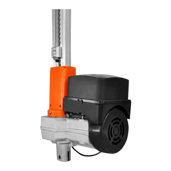
BV LEVANTE
WARNING:
Do not operate the equipment
Made by: Motoppar Indústria e Comércio de Automatizadores Ltda
without first reading the
Av. Dr. Labieno da Costa Machado, 3526 - Distrito Industrial - Garça - SP - CEP 17406-200 - Brasil
instruction manual.
CNPJ: 52.605.821/0001-55
P30501 - 08/2022
Rev. 0
www.ppa.com.br | +55 14 3407 1000
Advertisement
Table of Contents

Subscribe to Our Youtube Channel
Related Manuals for PPA BV LEVANTE


Summary of Contents for PPA BV LEVANTE
- Page 1 Made by: Motoppar Indústria e Comércio de Automatizadores Ltda without first reading the Av. Dr. Labieno da Costa Machado, 3526 - Distrito Industrial - Garça - SP - CEP 17406-200 - Brasil instruction manual. CNPJ: 52.605.821/0001-55 P30501 - 08/2022 Rev. 0 www.ppa.com.br | +55 14 3407 1000...
- Page 2 INDEX IMPORTANT SECURITY INSTRUCTIONS Recommendation: For the installation of the equipment, it is important that a PPA specialist installer follow all instructions given in this technical manual and in the user manual. IMPORTANT SECURITY INSTRUCTIONS ................... 3 With the user’s manual, the installer must TECHNICAL CHARACTERISTICS ....................
- Page 3 TECHNICAL CHARACTERISTICS TOOLS REQUIRED FOR INSTALLATION LEVANTE CUSTOM LEVANTE OPERATOR TYPE OVERHEAD OVERHEAD MODEL Single Phase Single Phase Here are some tools required to install the automation: RATED VOLTAGE 220 V / 127 V 220 V / 127 V NOMINAL FREQUENCY 60 Hz 60 Hz NOMINAL POWER...
- Page 4 PRECAUTIONS WITH THE GATE BEFORE - The cable for the fixed wiring must comply with NBR NM 247-3; AUTOMATION - The power conductor of a product for internal use must be a flexible cable 3 x 0.75 mm²; 500 V, according to the norm NBR NM 247-5;...
- Page 5 Step 3: Insert the closing stop with the rubber facing the drive nut. To install the equipment, follow the steps below: Step 1: The gate axis shall be between 100 mm and 300 mm below the central point of the gate leaf. ARTICULATING GATE LEAF HALF OF...
- Page 6 Step 6: Position the automation vertically on the door column and weld the mounting Step 9: With the gate closed, maintain a 50 mm tilt on the drive lever, respecting brackets on the column, respecting the measurements in the figure below. a distance from the center of the turning point of the drive lever and the center of the drive nut pin.
- Page 7 Assembly: that is available for download at www. Fairing: Gear: ppa.com.br and make all connections and configurations. MAINTENANCE In the table below, we will mention some PROBLEMS - DEFECTS, PROBABLE CAUSES AND CORRECTIONS - which may occur in your operator. Before any maintenance, it is necessary to completely disconnect the electricity.
Need help?
Do you have a question about the BV LEVANTE and is the answer not in the manual?
Questions and answers