
Related Manuals for SEW-Eurodrive M Series


Summary of Contents for SEW-Eurodrive M Series
- Page 1 Gearmotors \ Industrial Gear Units \ Drive Electronics \ Drive Automation \ Services D6.C00 Industrial Gear Units of the M.. Series M.P../M.R.. Horizontal Gear Units Edition 07/2004 perating Instructions 11279028 / EN...
- Page 2 SEW-EURODRIVE – Driving the world...
-
Page 3: Table Of Contents
Contents Important Notes....................4 Safety Notes ...................... 5 Transport of industrial gear units .............. 6 Corrosion protection and storage conditions .......... 10 Gear Unit Design ..................... 12 Basic design of the M..P.. series............. 12 Basic design of the M..R.. series ............13 Unit designation / nameplates.............. -
Page 4: Important Notes
The operating instructions contain important information about servicing; as a result, they should be kept in the vicinity of the gear unit. • It is essential to contact SEW-EURODRIVE regarding a subsequent change of mounting position! • The industrial gear units of the M.. series are delivered without oil fill. Refer to the information on the nameplate! •... -
Page 5: Safety Notes
Switch off the main motor if in doubt whenever changes occur in relation to normal operation (e.g. increased temperature, noise, vibration). Determine the cause; contact SEW-EURODRIVE if necessary. Inspection / Refer to the instructions in Sec. "Inspection and Maintenance."... -
Page 6: Transport Of Industrial Gear Units
Safety Notes Transport of industrial gear units Transport of industrial gear units Transport Tighten screwed in transport eyebolts [1] firmly. They are only designed for the weight eyebolts of the industrial gear unit including the motor connected via motor adapter; do not attach any additional loads. - Page 7 Safety Notes Transport of industrial gear units Transport of M.. Industrial gear units of the M.P.. / M.R.. series with motor adapter (→ following figure) industrial gear must only be transported using lifting ropes/chains [2] or lifting belts [1] at an angle units with motor of 90°...
- Page 8 Transport of industrial gear units Transport of M.. Industrial gear units of the M series on a base plate (→ following figure) must only be industrial gear transported with the lifting ropes [1] or chains (angle 90°) vertically to the base plate:...
- Page 9 Transport of industrial gear units Transport of M.. Industrial gear units of the M series with V-belt drive (with motors up to IEC size 200) industrial gear must only be transported using lifting ropes [2]. The eyebolts on the motor must not units with V-belt be used for transport.
-
Page 10: Corrosion Protection And Storage Conditions
The gear unit is delivered on a pallet without cover. protection • Protection of the inside of the gear unit: Gear units of the M series undergo a test run with protection oil. • Oil seals and seal surfaces are protected through bearing grease. - Page 11 The gear unit is packaged in a seaworthy plywood box and is delivered on a pallet. protection This way, the gear unit is protected from humidity and shock. SEW-EURODRIVE recommends a seaworthy package if the gear unit will be stored for an extended period of time or if protection against salty air is required.
-
Page 12: Gear Unit Design
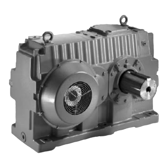
Gear Unit Design Basic design of the M..P.. series Gear Unit Design The following illustrations serve to explain the general design. Their only purpose is to facilitate the assignment of components to the spare parts lists. Discrepancies are possible depending on gear unit size and version! Basic design of the M..P.. -
Page 13: Basic Design Of The M
Gear Unit Design Basic design of the M..R.. series Basic design of the M..R.. series [10] [15] [25] [110] [35] [162] [299] [199] [210] [101] [310] [401] [110] [410] [201] [162] [411] [80] [301] [445] [399] [310] [210] [40] [10] [25] [35] 53382AXX... -
Page 14: Unit Designation / Nameplates
Gear Unit Design Unit designation / nameplates Unit designation / nameplates Sample unit designation Size: Horizontal 50 ... 90 Vertical 10 ... 90 Gear unit mounting: F = Foot mounting T = Torque arm Low speed shaft type (LSS): S = Solid shaft H = Hollow shaft (key or shrink disc connection) Mounting position: no designation: Horizontal... - Page 15 Gear Unit Design Unit designation / nameplates Example: Nameplate of the M series industrial gear unit, SEW-EURODRIVE Bruchsal/Germany M3PSF80 01.3115835301.0001.02 T09558 Nr. 2 Nr. 1 Pe kW MN2 kNm 2100 1:40.093 2004 Year n r/min 1480/36,9 ISO VG460 Miner.Oil/ca. 160 liter...
-
Page 16: Mounting Positions, Shaft Positions And Directions Of Rotation
The shaft positions (0, 1, 2, 3, 4) and directions of rotation shown in the following figures apply to output shafts (LSS) of the types solid shaft and hollow shaft. For other shaft positions or gear units with backstop, contact SEW-EURODRIVE. The following mounting positions (for a detailed overview, see → Sec. "Mounting Positions") and shaft positions (0, 1, 2, 3, 4) are possible:... - Page 17 Gear Unit Design Mounting positions, shaft positions and directions of rotation Directions of The directions of rotation of the outputs shaft (LSS) are defined as follows: rotation Gear unit version Direction of M.PS.. M.PH.. rotation M.RS.. M.RH.. Clockwise (CW) 53219AXX 53260AXX Gear unit version Direction of...
- Page 18 Gear Unit Design Mounting positions, shaft positions and directions of rotation Shaft positions The following figures show shaft positions and corresponding directions of rotation for and correspond- industrial gear units of the M2P.. series. ing directions of Two stages rotation of M2P.. industrial gear units 53224AXX...
- Page 19 Gear Unit Design Mounting positions, shaft positions and directions of rotation Shaft positions The following figures show shaft positions and corresponding directions of rotation for and correspond- industrial gear units of the M4P.. series. ing directions of Four stages rotation of M4P.. industrial gear units 53234AXX...
- Page 20 Gear Unit Design Mounting positions, shaft positions and directions of rotation Shaft positions The following figures show shaft positions and corresponding directions of rotation for and correspond- industrial gear units of the M4R.. four stage series. ing directions of Four stages rotation of M4R..
-
Page 21: Lubrication Of Industrial Gear Units
Gear Unit Design Lubrication of industrial gear units Lubrication of industrial gear units For M... gear units in horizontal design, the lubrication types "splash lubrication" or "pressure lubrication" are normally used. Splash Splash lubrication is used for industrial gear units of the M.. series in horizontal mounting lubrication position (unit designation M...). -
Page 22: Mechanical Installation
Fasteners for input and output elements ® • Lubricant (e.g. NOCO fluid from SEW-EURODRIVE) • For hollow shaft gear units (→ Sec. "Mounting/removal of hollow shaft gear units with keyed connection): Threaded rod, nut (DIN 934), retaining screw, ejector screw, end- plate •... -
Page 23: Gear Unit Foundation
SEW-EURODRIVE recommends foundation methods shown in the following figures. A customer’s own foundation method must be equally adequate. When mounting a gear unit onto steel framework, special attention should be paid to the rigidity of this framework to prevent destructive vibrations and oscillations. - Page 24 Mechanical Installation Gear unit foundation Concrete base The concrete base for the gear unit must be reinforced and interlocked with the concrete using steel clamps, steel rods or steel elements. Only the supporting girders are embedded in the concrete (Pos. "A" → following figure). ØTB ØTM Ød...
- Page 25 Mechanical Installation Gear unit foundation Dimensions Gear unit size Stud Foundation frame Foundation Supporting girders screws ∅TB ∅TM ∅d horizontal M... [mm] The minimum tensile strength of the supporting girders and foundation screws must be at least 350 N/mm Grouting The density of the grout must be equal to that of the base concrete.
-
Page 26: Mounting Of Solid Shaft Gear Units
Mechanical Installation Mounting of solid shaft gear units Mounting of solid shaft gear units Before mounting the gear unit, check the foundation dimensions with those in the corresponding drawings in Sec. "Gear unit foundation." Mount the gear unit in the following order: 1. - Page 27 Mechanical Installation Mounting of solid shaft gear units Mounting accuracy when aligning 53869AXX Figure 15: Mounting accuracy when aligning When aligning the gear unit, make sure that the mounting tolerances for the evenness of the foundation are not exceeded (values y in below table).
-
Page 28: Mounting / Removing Hollow Shaft Gear Units With Keyed Connection
– Circlips [3], end plate [4] Selecting the adequate thread and length of the threaded rod depends on the design of the customer’s machine. Thread sizes SEW-EURODRIVE recommends the following thread sizes: Gear unit size Quantity Thread size for • threaded rod [2] •... - Page 29 Mechanical Installation Mounting / removing hollow shaft gear units with keyed connection Mounting the hollow shaft gear unit onto the customer’s shaft Ø 180 Ø 180 52384AXX Figure 16: Mounting of horizontal gear unit with keyed connection [1] Customer’s shaft [4] End plate [2] Threaded rod [5] Nut...
- Page 30 Mechanical Installation Mounting / removing hollow shaft gear units with keyed connection Removing the hollow shaft gear unit from the customer’s shaft Ø 180 Ø 180 52458AXX Figure 18: Removing of horizontal gear unit with keyed connection [1] Customer’s shaft [3] Circlips [4] End plate [8] Ejector screw...
-
Page 31: Mounting / Removing Hollow Shaft Gear Units With Shrink Disc
– Threaded rod [2], nut [5], ejector screw [8], end plate screws [3], end plate [4] Selecting the appropriate thread and length of the threaded rod as well as the retaining screw depends on the design of the customer’s machine. Thread sizes SEW-EURODRIVE recommends the following thread sizes: Gear unit size Quantity Thread size for horizontal •... - Page 32 Mechanical Installation Mounting / removing hollow shaft gear units with shrink disc Recommended dimension of end plate [4] 53412AXX Figure 19: End plate design Gear unit size horizontal M... [mm] 6 x 60° [mm] 1 x M30 1 x M30 2 x M20 2 x M20 2 x M24...
- Page 33 Mechanical Installation Mounting / removing hollow shaft gear units with shrink disc Shrink disc on customer’s side of machine shaft [11] [10] [12] 53714AXX Figure 21: Mounting of horizontal gear unit with shrink disc connection [1] Customer’s shaft [7] Hollow shaft [2] Threaded rod [9] Shrink disc [3] End plate screws...
- Page 34 Mechanical Installation Mounting / removing hollow shaft gear units with shrink disc Mounted hollow Shrink disc opposite to customer’s side of machine shaft shaft gear unit [11] [12] [10] [9] 53471AXX Figure 22: Mounted horizontal gear unit with shrink-disc connection [1] Customer’s shaft [10] Locking screws [7] Hollow shaft...
- Page 35 Mechanical Installation Mounting / removing hollow shaft gear units with shrink disc Removing the Shrink disc opposite to customer’s side of machine shaft shrink disc [11] [10] 53470AXX Figure 24: Removing of horizontal gear unit with shrink disc connection [1] Customer’s shaft [7] Hollow shaft [4] End plate [10] Locking screws...
-
Page 36: Mounting A Motor With Motor Adapter
Mounting a motor with motor adapter Motor adapters [1] are available for mounting IEC motors of sizes 132 to 355 to industrial gear units of the M series. For assembly clearance between motor shaft end and shaft end of the gear unit, please refer to chapter "5.2 coupling"... -
Page 37: Mechanical Installation Options
Mechanical Installation Options Important installation instructions Mechanical Installation Options Important installation instructions Disconnect the motor from the power supply before starting work and secure it against unintentional restart! Important • Only use a mounting device for installing input and output elements. Use the center installation notes bore and the thread on the shaft end for positioning purposes. - Page 38 Mechanical Installation Options Important installation instructions The following methods for measuring angular and axial misalignment are important for complying with the mounting tolerances specified in Sec. "Mounting of couplings"! Measuring of The following figure shows the measurement for angular misalignment (α) using a feeler angular misalign- gauge.
- Page 39 Mechanical Installation Options Important installation instructions Measuring of The following figure shows the measurement for offset misalignment using a straight- offset misalign- edge. Permissible values for eccentricity are usually so small that the best measurement ment using results can be achieved with a micrometer dial. If you rotate one coupling half together straight-edge and with the micrometer dial and divide the deviation by two, the micrometer dial will indicate micrometer dial...
-
Page 40: Mounting Of Couplings
Mechanical Installation Options Mounting of couplings Mounting of couplings ROTEX coupling 51663AXX Figure 32: Design of the ROTEX coupling [1] Coupling hub [2] Ring gear The low-maintenance, elastic ROTEX coupling is capable of compensating radial and angular misalignment. Careful and exact alignment of the shaft ensures long service life of the coupling. - Page 41 Mechanical Installation Options Mounting of couplings Mounting the coupling halves onto the shaft 51689AXX Figure 33: Mounting dimensions of the ROTEX coupling Mounting dimensions Locking screw Coupling size (Alu/GG/GGG) (steel) Tightening torque [mm] [mm] [mm] [mm] [mm] [mm] [Nm] 10.5 The shaft distance must be strictly observed (dimension E) to ensure axial play of the coupling.
- Page 42 Mechanical Installation Options Mounting of couplings Nor-Mex The low-maintenance Nor-Mex couplings types G and E are torsionally flexible coupling, types G couplings capable of compensating axial, angular, and radial shaft misalignments. and E Torque is transmitted via an elastic element with high damping properties, which is also oil and heat resistant.
- Page 43 Mechanical Installation Options Mounting of couplings Mounting After having mounted the coupling halves, ensure that the recommended play instructions, (dimension S for type G, dimension S for type E) and the overall length (dimension L mounting dimen- for type G and dimension L for type E) corresponds with the dimensions given in the sions for Nor-Mex following tables.
- Page 44 Mechanical Installation Options Mounting of couplings Mounting dimensions of the Nor-Mex E coupling 51674AXX Figure 36: Mounting dimensions of the Nor-Mex E coupling Mounting dimensions Nor-Mex E Permitted tolerance S Weight Coupling size [mm] [mm] [mm] [kg] 62.5 2.5± 0.5 0.93 3±...
- Page 45 Mechanical Installation Options Mounting of couplings Mounting tolerances Offset misalignment Angular misalignment 51688AXX Figure 37: Mounting tolerances The mounting tolerances specified in the following table apply to elastic Nor-Mex and ROTEX couplings. Mounting tolerances [mm] Outside diameter D –1 –1 –1 n <...
- Page 46 Mechanical Installation Options Mounting of couplings Mounting of torsionally rigid GM, GMD, and GMX couplings [9,8] [1] [6] [11] [12] [17] [9,8] [11] [10] [5] [7] [13,14] [15,16] GM 42-260 GM 280-800 53262AXX Figure 38: Design of the GM coupling [1] Coupling hub [10] Gasket [2] Sleeve...
- Page 47 Mechanical Installation Options Mounting of couplings Mounting tolerances Offset misalignment Angular misalignment 51690AXX Figure 39: Mounting tolerances of the GM coupling Mounting tolerances [mm] –1 –1 –1 –1 –1 Coupling type n < 250 min n: 250 -500 min n: 500-1000min n: 1000-2000min n: 2000-4000min –...
-
Page 48: Backstop
• Contact SEW-EURODRIVE if you want to alter the blocking direction! The maintenance-free type backstop is a centrifugally operated backstop with sprags that lift off. Once the lift-off speed is reached, the sprags completely lift off from the con- tact surface of the outer ring. -
Page 49: Installation With Steel Frame
Installation with steel frame Installation with steel frame For industrial gear units of the M series in horizontal mounting position (M2P.., M3P.., M4P.., M3R.., M4R.., M5R..), SEW-EURODRIVE supplies preassembled drive packages on a steel frame (swing base or base frame). -
Page 50: Torque Arm
Mechanical Installation Options Torque arm Base frame A base frame is a steel frame [1] that accommodates gear unit, (fluid) coupling and motor (and brake, if required). The steel frame is supported by several foot mountings [2]. Such a frame is usually used for solid shaft gear units with elastic coupling on the output shaft. - Page 51 Mechanical Installation Options Torque arm M2P../M3R.. 0° ± 1° 1° [5409] [5410] [5413] [5410] 53273AXX Figure 44: Torque arm directly mounted to the gear unit [1] Sufficient play [5409] Anchor plate [5410] Anchoring rod [5413] Anchor plate M3P../M4P../M4R../ M5R.. 0° ±...
- Page 52 Mechanical Installation Options Torque arm Foundation for To build the foundation for the torque arm directly mounted to the gear unit or mounted the torque arm to the swing base of the motor, do the following: • Place the supporting girders horizontally in their fixed locations. Embody the supporting girders in the base concrete (A).
-
Page 53: Mounting Of V-Belt Drive
Mechanical Installation Options Mounting of V-belt drive Mounting of V-belt drive A V-belt drive is used when the overall gear ratio needs to be adjusted. The standard scope of delivery includes motor bracket, belt pulleys, V-belts and belt guard. [5214] [5110] [5260] [5210]... - Page 54 Mechanical Installation Options Mounting of V-belt drive – Make sure that the belt pulleys [5214, 5216] are aligned accurately. Check correct alignment using a steel ruler making contact at four points (→ following figure). 51697AXX Figure 48: Alignment check of belt pulleys –...
-
Page 55: Oil Heater
Mechanical Installation Options Oil heater Oil heater Oil heating is required to ensure lubrication at startup when the ambient temperature is low (e.g. cold start of the gear unit). → Purpose and The oil heater consists of 3 basic parts ( Figure 49) basic design 1. - Page 56 Mechanical Installation Options Oil heater The thermostat and the oil heater are normally installed to the gear unit and are ready to operate but without electrical connections. Therefore, the following has to be done before startup: 1. Connect the resistor element ("Oil heater") with the power supply 2.
- Page 57 Mechanical Installation Options Oil heater Basic design thermostat 53993AXX Figure 51: Basic design thermostat [1] Setting range knob [2] IP66 enclosure (units with external reset IP54) → [3] 2 x PG 13.5 cable diameter 6 mm 14 mm [4] SPDT contact system. Exchangeable [5] Capillary tube length up to 10 m [6] Stainless steel bellows [7] Polyamide cover...
- Page 58 Mechanical Installation Options Oil heater Basic design thermostat RT thermostats Ambient temperature -50 °C to 70 °C Contact system [1] Line [2] SPDT Alternating current: AC-1: 10 A, 400 V Contact load AC-3: 4 A, 400 V AC-15: 3A, 400 V 0.48 Direct current: DC-13: 12 W, 230 V...
- Page 59 Mechanical Installation Options Oil heater Adjusting the The setpoint is normally set at the factory. For adjustments, the following process has setpoint to be followed: The range is set by using the setting knob [1] while at the same time reading the main scale [2].
-
Page 60: Temperature Sensor Pt100
Mechanical Installation Options Temperature sensor PT100 Temperature sensor PT100 The temperature sensor PT100 can be used to measure the temperature of the oil in the gear unit. Dimensions PG9, PG11 R1/2 50533AXX Figure 54: Temperature sensor PT100 Electrical connection 50534AXX Figure 55: Electrical connection temperature sensor PT100 ×... -
Page 61: Spm Adapter
Mechanical Installation Options SPM adapter SPM adapter SPM adapters are available for measuring the shock pulses of the gear unit bearings. Shock pulses are measured using shock pulse sensors attached to the SPM adapter. Nipple 32000 and g = M8 cover 81025 L = 24, 113, 202, 291 53871AXX... - Page 62 Mechanical Installation Options SPM adapter Mounting position of SPM - adapter 53263AXX Figure 58: M2P.../M3R... Position SPM - adapter M2P../M3R.. Nipples [1] and [2] are on both sides of the gear unit. Nipple [3] only for bevel-helical gear units (M.R..) 53264AXX Figure 59: M3P.../M4P ..Position SPM - adapter M3P../M4P..
- Page 63 Mechanical Installation Options SPM adapter 53267AXX Figure 60: M4R.. Position SPM - adapter M4R.. Nipples [1] and [2] are on both sides of the gear unit. 53269AXX Figure 61: M5R.. Position SPM - adapter M5R.. Nipples [1], [2] and [3] are on both sides of the gear unit. Operating Instructions –...
- Page 64 Mechanical Installation Options SPM adapter Mounting of shock pulse sensor 51885AX Figure 62: Mounting the shock pulse sensor onto the SPM adapter [1] SPM adapter [2] Pulse sensor • Remove the protection cap of the SPM adapter [1]. Ensure that the SPM adapter [1] is tightened correctly and securely (tightening torque: 15 Nm).
-
Page 65: 5.10 Fan
Mechanical Installation Options 5.10 Fan A fan can be mounted if the projected thermal power of the gear unit is exceeded. The direction of rotation of the gear unit does not influence the operation of the fan. M2P.., M3P.. ∅ FD 53383AXX Figure 63: Fan [1] Fan on the opposite side as the motor... - Page 66 Mechanical Installation Options M3R.. 51641AXX Figure 64: Fan Gear Unit [mm] ∅ M3R50 3000 ∅ M3R60 3000 1129 ∅ M3R70 2350 1278 ∅ M3R80 2350 1328 ∅ M3R90 2350 1499 Outer diameter of the fan Make sure that air intake vents are not blocked or covered! Operating Instructions –...
-
Page 67: Cooling Coil
Mechanical Installation Options Cooling coil 5.11 Cooling coil The cooling coil increases the thermal power of the gear unit by cooling the oil bath. The cooling coil is a helical pipe with water flowing through it. The cooling coil is located in the oil bath inside the gear unit. -
Page 68: Pressure Lubrication
Pressure Lubrication Shaft end pump Pressure Lubrication For gear units equipped with a separate lubrication system (sometimes in connection with a cooling system) refer also to the separate manual. Shaft end pump The maintenance-free shaft end pump RHP [1] is suited for operation in both directions of rotation.. - Page 69 Pressure Lubrication Shaft end pump Pump suction The intake and delivery pipe or tube is connected disregarding the direction of rotation of the output shaft and must not be altered. If the shaft end pump does not build up pressure within 10 seconds after the gear unit has been started (→ Flow monitoring via oil sight glass on the gear unit), do the following: 51646AXX Figure 67: Shaft end pump...
-
Page 70: Motor Pump
Supply voltage: 220-240 V / 380-420 V, 50 Hz Instrumentation IP See shaft end pump Consult SEW-EURODRIVE in case of deviating supply voltages and/or 60 Hz operation. For a detailed description, please refer to the separate manual. Other optional instruments (flow monitor, temperature monitor, ...) and optional equip- ment (oil filter, ...) are also available. -
Page 71: Customer Supplied External Cooling And Lubrication Systems
Customer supplied external cooling and lubrication systems Customer supplied external cooling and lubrication systems Genaral If the customer orders a gear unit for which SEW-EURODRIVE recommends a pressure lubrication or/and an additional cooling system, this chapter provides some guidelines for selecting the components. - Page 72 Pressure Lubrication Customer supplied external cooling and lubrication systems Selecting the cooling capacity (1 - η ) [kW] = power loss to be cooled [kW] = gear unit running load [kW] = gear unit thermal rating (from catalog) η = gear unit efficiency η...
- Page 73 Pressure Lubrication Customer supplied external cooling and lubrication systems Typical setup pressure lubrication 53986AXX Figure 69: Pressure lubrication [1] Motor pump [2] Filter [3] Pressure switch [4] Visual thermometer [5] Pressure relief valve [G] Gear unit Typical setup pressure lubrica- tion with oil/water cooler 53988AXX...
- Page 74 Pressure Lubrication Customer supplied external cooling and lubrication systems Typical setup pressure lubrica- tion with oil/water cooler 53989AXX Figure 71: Setup of pressure lubrication with oil/water cooler [1] Pump [2] Filter [3] Oil cooler [4] Thermo switch 50 °C [5] Thermometer [6] Pressure gauge [7] Pressure switch [G] Gear unit...
-
Page 75: Startup
Startup Startup of M gear units Startup Startup of M gear units • It is essential to adhere to the safety notes in Sec. "Safety Notes." • It is absolutely necessary to avoid open flames or sparking when working with the gear unit! •... -
Page 76: Startup Of M Gear Units With Backstop
Startup Startup of M gear units with backstop Running-in SEW-EURODRIVE recommends running-in the gear unit as first startup phase. period Increase load and revolutions in two to three steps up to maximum level. The running- in phase takes about 10 hours. -
Page 77: Inspection And Maintenance
Inspection and Maintenance Inspection and maintenance intervals Inspection and Maintenance Inspection and maintenance intervals Interval What to do? • Check the housing temperature: – with mineral oil: max 90 °C – with synthetic oil: max. 100 °C • Daily • Check gear unit noise •... -
Page 78: Lubricant Change Intervals
Inspection and Maintenance Lubricant change intervals Lubricant change intervals Change the oil more frequently when operating the industrial gear unit under more severe/aggressive environmental conditions! Mineral CLP lubricants and synthetic polyalphaolefin-based (PAO) lubricants are used for lubrication. The synthetic lubricant CLP HC (according to DIN 51502) shown in the following figure corresponds to the PAO oils. -
Page 79: Inspection And Maintenance Of The Gear Unit
Inspection and Maintenance Inspection and maintenance of the gear unit Inspection and maintenance of the gear unit • Do not mix different synthetic lubricants and do not mix synthetic with mineral lubricants! • For positions of the oil level plug, the drain plug, the breather plug and the oil sight glass, refer to Sec. - Page 80 If you remove the housing cover, you must apply new sealing compound to the sealing surface. Else, the tightness of the gear unit is not guaranteed! Contact SEW-EURODRIVE in this case! Cleaning the oil Incrustation on the oil heater caused by oil must be removed. Remove the oil heater for heater this purpose.
- Page 81 Inspection and Maintenance Inspection and maintenance of the gear unit Removing the oil heater 90 mm 51642AXX Figure 73: Oil heater M.. horizontal gear units [1] Oil heater [2] Temperature sensor [3] Thermostat • Remove the oil heater [1] and the gasket on the gear unit. •...
-
Page 82: Malfunctions
Malfunctions Gear unit malfunctions Malfunctions Gear unit malfunctions Problem Possible cause Solution Unusual, regular running Meshing/grinding noise: bearing damage Check the oil (→ Sec. "Inspection and Mainte- noise Knocking noise: irregularity in the gearing nance"), replace bearings Contact customer service Unusual, irregular running Foreign particles in the oil •... -
Page 83: Symbols And Mounting Positions
Symbols and Mounting Positions Symbols used Symbols and Mounting Positions 10.1 Symbols used The following table shows which symbols are used in the subsequent figures and what they mean. Symbol Meaning Breather plug Inspection opening Oil filling plug Oil drain plug/oil drain valve Oil level glass The positions of the elements are exemplary and cover most of the cases. -
Page 84: Symbols And Mounting Positions Of M.p.. Gear Units
Symbols and Mounting Positions Symbols and Mounting Positions of M.P.. gear units 10.2 Symbols and Mounting Positions of M.P.. gear units Mounting position M.P.. 53520AXX Figure 74: Mounting positions of M.P.. gear units 10.3 Symbols and mounting positions of M.R.. gear units Mounting position M.R.. -
Page 85: Lubricants
The FZG stage should be at least 12 according to DIN 51354. The oil must also contain EP additivies. If synthetic oils are selected due to operating temperatures or oil change intervals, SEW-EURODRIVE recommends polyalfaolefin based (PAO) oil. Mineral oils... - Page 86 Lubricants Guideline for oil and grease selection Synthetic oils (PAO) Lubricating oil Lubricating oils are grouped in ISO VG viscosity classes according to standards ISO standards 3448 and DIN 51519. ISO VG ISO 6743-6 class designation ISO-L-CKT 150 ISO-L-CKT 220 ISO-L-CKT 320 ISO-L-CKT 460 Containing EP additives...
- Page 87 Lubricants Guideline for oil and grease selection Slow speed gear When the pitch line velocity of the slowest stage is under 1 m/s (n < 15 1/min), the gear units unit operates in boundary lubrication area. It is recommended to use: •...
- Page 88 Lubricants Guideline for oil and grease selection Mineral oils 3000 2000 150 320 220 460 1000 10 20 30 40 50 60 70 80 90 100 °C 53995AXX Figure 76: Mineral oils [1] Oil temperature [2] Operating oil viscosity [3] Oil ISO VG viscosity class Synthetic PAO oils 3000...
-
Page 89: Overview Of Lubricants For M.. Industrial Gear Units
Lubricants Overview of lubricants for M.. industrial gear units 11.2 Overview of lubricants for M.. industrial gear units Mineral lubricants ISO VG AGMA Company Viscosity Pour point class number cSt / 40 °C °C Aral Degol BG150 –24 Energol GR-XP150 –27 Castrol Alpha SP150... - Page 90 Lubricants Overview of lubricants for M.. industrial gear units ISO VG AGMA Company Viscosity Pour point class number cSt / 40 °C °C Aral Degol BG220 –21 Energol GR-XP220 –27 Castrol Alpha SP220 –21 Castrol Alphamax 220 –24 Chevron Industrial Oil EP220 –12 Falcon CLP220 –18...
- Page 91 Lubricants Overview of lubricants for M.. industrial gear units ISO VG AGMA Company Viscosity Pour point class number cSt / 40 °C °C Aral Degol BG320 –18 Energol GR-XP320 –24 Castrol Alpha SP320 –21 Castrol Alphamax 320 –18 Chevron Industrial Oil EP320 –9 Falcon CLP320 –18...
- Page 92 Lubricants Overview of lubricants for M.. industrial gear units ISO VG AGMA Company Viscosity Pour point class number cSt / 40 °C °C Aral Degol BG680 –12 Energol GR-XP680 –9 Castrol Alpha SP680 –6 Falcon CLP680 –12 Esso Spartan EP680 –15 Exxon Spartan EP680...
- Page 93 Lubricants Overview of lubricants for M.. industrial gear units Synthetic The synthetic polyalphaolefin-based lubricants correspond to the CLP HC oils polyalphaolefin (according to DIN 51502). (PAO) based ISO VG AGMA Company Viscosity Pour point lubricant class number °C 40 °C 100 °C Intor HCLP150 19.8...
-
Page 94: Sealing Grease
43.7 –33 Tribol Tribol 1710 / 460 –30 11.3 Sealing grease SEW-EURODRIVE recommends the grease types listed in below table for operating temperatures from – 30 °C to +100 °C. Company Penetration NLGI 2 (EP) Drop point °C Aral Aralub HLP2... -
Page 95: Lubricant Fill Quantities
Lubricants Lubricant fill quantities 11.4 Lubricant fill quantities The specified fill quantities are guide values. The precise values vary depending on the gear ratio. M.P.. Oil volume [l] Gear unit size Lubrication type Two stages Three stages Four stages M.P.. M2P..
Need help?
Do you have a question about the M Series and is the answer not in the manual?
Questions and answers