
Related Manuals for SEW-Eurodrive MOVIGEAR MGF-DBC Series


Summary of Contents for SEW-Eurodrive MOVIGEAR MGF-DBC Series
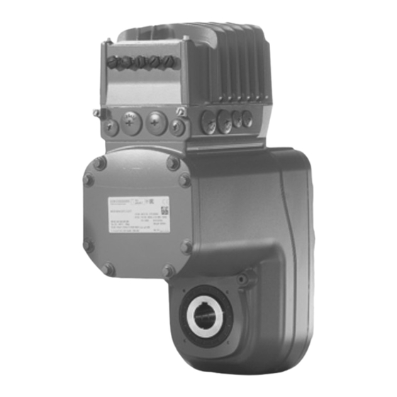
- Page 1 *27802604_0423* Drive Technology \ Drive Automation \ System Integration \ Services Operating Instructions Mechatronic Drive Unit ® MOVIGEAR performance DBC MGF..-DBC (Binary) Edition 04/2023 27802604/EN...
- Page 2 SEW-EURODRIVE—Driving the world...
-
Page 3: Table Of Contents
Table of Contents Table of Contents General information........................ 5 Structure of the safety notes ................... 5 ® MOVIGEAR performance safety notes.................. 6 Target group ........................ 6 Designated use ....................... 6 Functional safety technology .................. 7 Transportation......................... 8 Creating a safe working environment ................ 9 Installation/assembly..................... 11 Protective separation .................... 11 Electrical installation ..................... 11 Startup/operation ...................... 11 2.10... - Page 4 Table of Contents Control elements...................... 74 DIP switches ......................... 77 Startup procedure ...................... 80 Startup with CBG22A on-site keypad ................ 82 Configuring the digital inputs/outputs................ 82 Setpoint scaling of the analog input ................ 83 ® 6.10 Deactivating DynaStop for the startup procedure ............ 84 6.11 Configuring the drive behavior at standstill (FCB 02, FCB 13, FCB 14) ....... 86 Operation..........................
-
Page 5: General Information
General information Structure of the safety notes General information Structure of the safety notes 1.1.1 Meaning of signal words The following table shows the graduation and meaning of the signal words in the warnings: Signal word Meaning Consequences if not observed Imminent danger Death or severe injuries DANGER... -
Page 6: Movigear Performance Safety Notes
® MOVIGEAR performance safety notes Target group ® MOVIGEAR performance safety notes Target group Specialist for me- Any mechanical work may be performed only by adequately qualified specialists. Spe- chanical work cialists in the context of this documentation are persons who are familiar with the design, mechanical installation, troubleshooting, and maintenance of the product, and who possess the following qualifications: •... -
Page 7: Functional Safety Technology
® MOVIGEAR performance safety notes Functional safety technology For applications with inclining tracks, you must only use the product after a risk as- sessment is performed by the user. For further information, consult the information in the documentation. 2.2.2 Restrictions of use The following applications are prohibited unless the device is explicitly designed for such use: •... -
Page 8: Transportation
® MOVIGEAR performance safety notes Transportation Transportation Inspect the shipment for damage as soon as you receive the delivery. Inform the ship- ping company immediately about any damage. If the product or the packaging is dam- aged, do not assemble, install, connect, or start up the product. If the packaging is damaged, the product itself may also be damaged. -
Page 9: Creating A Safe Working Environment
® MOVIGEAR performance safety notes Creating a safe working environment Creating a safe working environment Before you work on the product, ensure a safe working environment. Observe the fol- lowing basic safety note: 2.5.1 Performing work on the product safely Defective or damaged product Never install defective or damaged products. - Page 10 ® MOVIGEAR performance safety notes Creating a safe working environment 2.5.2 Performing electrical work safely Observe the following information to perform electrical work safely: Electrical work may only be performed by a qualified electrician or an electronically in- structed person under the supervision of an electrician. Observe that the fact that the operation LED and other display elements are no longer illuminated does not indicate that the product has been disconnected from the supply system and no longer carries any voltage.
-
Page 11: Installation/Assembly
® MOVIGEAR performance safety notes Installation/assembly • Ensure that the unit is de-energized. • Please also observe the labels and hazard symbols on the product. Installation/assembly Ensure that the product is installed and cooled in accordance with the regulations in the documentation. -
Page 12: Magnetic Fields
® MOVIGEAR performance safety notes Magnetic fields Depending on the degree of protection, products may have live, uninsulated, and sometimes moving or rotating parts as well as hot surfaces during operation. Never plug or unplug plug connectors while they are energized. Do not separate the connection to the product during operation. -
Page 13: Device Structure
Device structure Example nameplate and type designation of the drive unit Device structure Example nameplate and type designation of the drive unit ® 3.1.1 MOVIGEAR performance DBC nameplate The following figure shows an example of a drive unit nameplate. The format of the type designation can be found in chapter entitled “Type designation ...”. - Page 14 Device structure Example nameplate and type designation of the drive unit ® 3.1.2 MOVIGEAR performance DBC type designation The following table shows the type designation of the drive unit. Product family ® MG = MOVIGEAR Gear unit type F = Parallel-shaft helical gear unit Shaft design A = Shaft-mounted gear unit (hollow shaft with key) ®...
-
Page 15: Electronics
Device structure Electronics Electronics 3.2.1 Overview of electronics cover Devices with the following electronics covers are available depending on the nominal output current: Electronics cover Nominal out- Type designation Size Image put current 2.0 A DBC...-0020.. Size 1 without cooling fins 2.5 A DBC...-0025.. - Page 16 Device structure Example nameplate and type designation of electronics 3.3.2 Outer nameplate of DBC.. electronics cover The following figure gives an example of a nameplate of the electronics cover. For the structure of the type designation, refer to chapter "Type designation of the electronics cover".
-
Page 17: Markings
Device structure Markings Connection voltage 5 = AC 500 V Power section design EMC 0 = Basic interference suppression 1 = IT system design Connection type 3 = 3-phase – Version – Device variant 0 = Standard Technology level 0 = Technology level 0 (standard) Application level 0 = Application level 0 (standard) –... - Page 18 Device structure Markings The UL and cUL markings state UL approval. cUL is equally eligible for approval by the CSA. The UKCA mark states compliance with British guidelines. The EAC mark states compliance with the requirements of the technical regulations of the Customs Union (Eurasian Economic Union), Armenia, Belarus, Kazakhstan, Kyrgyzstan, and Russia.
-
Page 19: Mechanical Installation
Mechanical installation Installation notes Mechanical installation Installation notes Perform the following steps before installation: WARNING! Electric shock caused by dangerous voltages in the connection box. Severe or fatal injuries. De-energize the device. Pay attention to the 5 safety rules in chapter “Carrying out electrical work safely”. -
Page 20: Setting Up The Drive Unit
Mechanical installation Setting up the drive unit • Clean the output shafts and flange surfaces thoroughly to ensure that they are free of anti-corrosion agents, contamination or similar. Use a commercially available solvent. Do not expose the sealing lips of the oil seals to the solvent – damage to the material. - Page 21 Mechanical installation Setting up the drive unit 4.4.3 Electronics cover Installing the electronics cover Install the electronics cover as follows: WARNING! Risk of burns due to hot surfaces. Severe injuries. Let the device cool sufficiently before touching it. 2. NOTICE! Loss of the guaranteed degree of protection. Possible damage to prop- erty.
- Page 22 Mechanical installation Setting up the drive unit Removing the electronics cover Remove the electronics cover as follows: WARNING! Risk of burns due to hot surfaces. Severe injuries. Let the device cool sufficiently before touching it. 2. Undo the screws of the electronics cover. 3.
- Page 23 Mechanical installation Setting up the drive unit 4.4.7 Gear unit venting Drive units with installed breather valve Except for the mounting position M3, SEW‑EURODRIVE delivers all drive units ordered for a specific mounting position with a breather valve that is activated and in- stalled according to the specific mounting position.
- Page 24 Mechanical installation Setting up the drive unit Mounting the breather valve in mounting position M1 The following figure shows an example of how to mount the breather valve in mount- ing position M1: Example: Mounting position M1 25343401227 ® Operating Instructions – MOVIGEAR performance DBC...
- Page 25 Mechanical installation Setting up the drive unit Activating the breather valve For designs with screwed-in breather valve, check whether the breather valve is acti- vated. If not, remove the transport protection of the breather valve before starting up the drive unit. Activate the breather valve as follows: 1.
- Page 26 Mechanical installation Setting up the drive unit Pressure compensation fitting installation positions The following table shows the installation location-dependent mounting positions of the pressure compensation fitting (option/PE): Mounting position M1, M3*, M5, M6 25344067723 Mounting position M2, M4 25344146955 * Mounting position M3 is only possible with the option "integrated pressure com- ®...
-
Page 27: Shaft-Mounted Gear Unit With Keyway
Mechanical installation Shaft-mounted gear unit with keyway Shaft-mounted gear unit with keyway INFORMATION Concerning the customer shaft design, refer to the design notes in the product manual > chapter "Technical data". INFORMATION To avoid contact corrosion, SEW‑EURODRIVE recommends that the customer shaft should additionally be lathed down between the 2 contact surfaces! 4.5.1 Mounting the drive unit... -
Page 28: Customer Shaft With Contact Shoulder
Mechanical installation Shaft-mounted gear unit with keyway 3. Install the shaft and secure it in an axial manner (installation is facilitated by using a fitting tool). The 3 installation types are described below: ð 3A: Standard scope of delivery 9007220768364043 Short retaining screw (standard scope of delivery) Lock washer Washer... - Page 29 Mechanical installation Shaft-mounted gear unit with keyway 9007220768369931 Retaining screw Lock washer Washer Retaining ring Spacer tube Customer shaft without contact shoulder 4. Tighten the retaining screw with the specified torque (see "Tightening torques for retaining screws" chapter). 9007220768463371 4.5.2 Retaining screw tightening torques Tighten the retaining screws with the following tightening torques: Drive...
- Page 30 Mechanical installation Shaft-mounted gear unit with keyway The following description only applies when the drive is assembled using the SEW‑EURODRIVE assembly/disassembly kit (see previous description, points 2B or 2C). 1. Perform the steps according to chapter "Installation notes" (→ 2 19). WARNING! Risk of burns due to hot surfaces. Severe injury. Let the devices cool down sufficiently before touching them.
- Page 31 Mechanical installation Shaft-mounted gear unit with TorqLOC® (customer shaft without contact shoulder) Shaft- mounted gear unit with TorqLOC® (customer shaft without contact shoulder) ® Shaft-mounted gear unit with TorqLOC (customer shaft without contact shoulder) Mount the drive unit on the shaft as follows: 1.
- Page 32 Mechanical installation Shaft-mounted gear unit with TorqLOC® (customer shaft without contact shoulder) ® 5. Apply NOCO fluid on the bushing and spread thoroughly. 21528905739 6. Push the gear unit onto the customer shaft. 9007220783649163 7. Mount the torque arm onto the system structure/holding fixture (do not tighten the screws).
- Page 33 Mechanical installation Shaft-mounted gear unit with TorqLOC® (customer shaft without contact shoulder) 8. Push the bushing into the gear unit up to the stop. 9007220783654027 9. Push the stop ring to the bushing. Mark the position of the stop ring. 9007220783656459 ®...
- Page 34 Mechanical installation Shaft-mounted gear unit with TorqLOC® (customer shaft without contact shoulder) 10. Remove the torque arm from the holding fixture/system structure. 9007220783658891 11. Pull the gear unit off the customer shaft until the stop ring is accessible for fasten- ing.
- Page 35 Mechanical installation Shaft-mounted gear unit with TorqLOC® (customer shaft without contact shoulder) 18014420037795339 14. Push the bushing and the gear unit onto the customer shaft up to the fixed stop ring. 9007220783619979 15. Mount the torque arm onto the system structure/holding fixture again (do not tighten the screws).
- Page 36 Mechanical installation Shaft-mounted gear unit with TorqLOC® (customer shaft without contact shoulder) 16. Make sure that all screws are loosened and slide the shrink disk onto the hollow shaft. 18014420038365835 17. Slide the counter bushing onto the customer shaft and into the hollow shaft. 18014420038368267 18.
- Page 37 Mechanical installation Shaft-mounted gear unit with TorqLOC® (customer shaft without contact shoulder) 20. Make sure that the customer shaft is seated in the counter bushing. 18014420038373131 21. Tighten the screws of the shrink disk only hand-tight and ensure that the outer rings of the shrink disk are plane-parallel.
- Page 38 Mechanical installation Shaft-mounted gear unit with TorqLOC® (customer shaft without contact shoulder) 23. After installation, make sure the remaining gap s between the outer rings of the shrink disks is > 0 mm. ð The remaining gap between counter bushing and hollow shaft end as well as bushing and stop ring must be > 0 mm.
- Page 39 Mechanical installation Shaft-mounted gear unit with TorqLOC® (customer shaft with contact shoulder) Shaft- mounted gear unit with TorqLOC® (customer shaft with contact shoulder) ® Shaft-mounted gear unit with TorqLOC (customer shaft with contact shoulder) Mount the drive unit on the shaft as follows: 1.
- Page 40 Mechanical installation Shaft-mounted gear unit with TorqLOC® (customer shaft with contact shoulder) 4. Slide the bushing onto the customer shaft. 0 mm 21528993931 ® 5. Apply NOCO fluid on the bushing and spread thoroughly. 21528996363 6. Push the gear unit onto the customer shaft. 9007220783739787 ®...
- Page 41 Mechanical installation Shaft-mounted gear unit with TorqLOC® (customer shaft with contact shoulder) 7. Make sure that all screws are loosened and slide the shrink disk onto the hollow shaft. 18014420038483211 8. Slide the counter bushing onto the customer shaft and into the hollow shaft. 18014420038485643 9.
- Page 42 Mechanical installation Shaft-mounted gear unit with TorqLOC® (customer shaft with contact shoulder) 11. Make sure that the customer shaft is seated in the counter bushing. 18014420038490507 12. Tighten the screws of the shrink disk only hand-tight and ensure that the outer rings of the shrink disk are plane-parallel.
- Page 43 Mechanical installation Shaft-mounted gear unit with TorqLOC® (customer shaft with contact shoulder) 15. The remaining gap between counter bushing and hollow shaft end must be > 0 mm. > 0 mm > 0 mm 21528986635 16. Mount the torque arm and firmly tighten it. Observe chapter "Torque arm" (→ 2 46).
-
Page 44: Shaft-Mounted Gear Unit With Torqloc - Disassembly, Cleaning, Lubrication
Mechanical installation Shaft-mounted gear unit with TorqLOC® – disassembly, cleaning, lubrication Shaft- mounted gear unit with TorqLOC® – d isassembl y, cleaning, lubrication ® Shaft-mounted gear unit with TorqLOC – disassembly, cleaning, lubrication 4.8.1 Removing the drive unit Remove the drive unit from the shaft as follows: 1. -
Page 45: Installing The Protective Cover
Mechanical installation Installing the protective cover 4.8.2 Cleaning and lubrication There is no need to dismantle removed shrink discs before they are reinstalled. 1. Clean and lubricate the shrink disk if it is dirty. 2. Lubricate the tapered surfaces with one of the following solid lubricants: Lubricant (Mo S2) Sold as Molykote 321 (lube coat) -
Page 46: Torque Arm
Mechanical installation Torque arm 3. Fasten the safety cover in the bore provided for this purpose using the enclosed screw and serrated lock washer. The permitted tightening torque for the M4×10 screw is 3.3 Nm. 36010468747 Bore Serrated lock washer M4×10 screw 4.9.2 Installation without cover In certain individual cases (e.g. - Page 47 Mechanical installation Torque arm 4.10.1 Installation options The following figure shows the possible mounting positions of the torque arm: 25347868811 Torque arm axis length Bore diameter Torque arm thickness Bush with bearings on both ends The following table shows the required tightening torques: Drive Torque arm Tightening torque...
-
Page 48: Tightening Torques
Mechanical installation Tightening torques 4.11 Tightening torques ® 4.11.1 Example of MOVIGEAR performance The following figure shows an example of the installation of the threaded blanking plugs, cable glands and electronics cover. The number and position of threaded blank- ing plugs and cable bushings depend on the ordered variant. 38411008907 Tighten the screws step by step in a diametrically opposite sequence with a tightening torque of 6.0 Nm. - Page 49 Mechanical installation Tightening torques 4.11.2 Tightening torques for cable glands Tighten cable glands optionally included delivery SEW‑EURODRIVE with the following torques: Screw fitting Part Contents Size Outer di- Tighten- number (pieces) ameter of cable torque (mm) (Nm) EMC cable glands 18204783 10 M16 ×...
-
Page 50: Electrical Installation
Electrical installation Installation instructions Electrical installation Installation instructions 5.1.1 Permitted voltage systems Information on voltage supply sys- Information on permissibility tems TN and TT systems – voltage sys- Use is possible without restrictions. tems with directly grounded star point IT systems – voltage systems with Use is only permitted with electronics cover in non-grounded star point IT system design (...-513-..). - Page 51 Electrical installation Installation instructions 5.1.3 Permitted cable cross section of terminals Line terminals X1 Observe the permitted cable cross sections for installation: Line terminals X1 Without conductor end With conductor end sleeve sleeves (with or without plastic collar) Connection cross sec- 0.5 mm –...
- Page 52 Electrical installation Installation instructions 5.1.4 Activating line terminals X1 Adhere to the following sequence when actuating the line terminals X1: 25649924107 5.1.5 Activating terminals X3 for the braking resistor Adhere to the following sequence when actuating the X3 terminals for the braking re- sistor: 25650172171 5.1.6...
- Page 53 Electrical installation Installation instructions 5.1.7 Selecting the residual current device The inverter can cause a direct current in the protective earthing conductor. Proceed as follows when selecting the residual current device: 1. If using a residual current device is not mandatory according to the standards, SEW‑EURODRIVE recommends not using a residual current device.
- Page 54 Electrical installation Installation instructions 5.1.9 Notes on PE connection ® PE connection to MOVIGEAR with handle The handle is only used to transport the unit. The handle is not required for operation. 1. Remove the handle. Store the handle for future service work. 2.0 –...
- Page 55 Electrical installation Installation instructions ® PE connection to MOVIGEAR with guard bracket The guard bracket is for the permanent protection of the device. Do not remove the guard bracket. 1. Connect the PE cable to the guard bracket according to the following figure. 2.0 –...
- Page 56 Electrical installation Installation instructions Leakage currents Earth-leakage currents ≥ 3.5 mA can occur during normal operation. In order to fulfill EN 61800-5-1, observe the following notes: • The protective earth (PE) connection must meet the requirements for systems with high earth-leakage currents. • This usually means –...
- Page 57 Electrical installation Installation instructions 5.1.12 Installation above 1000 m amsl The devices can be used at altitudes above 1000 m above sea level up to 3800 m above sea level under the following marginal conditions. The maximum altitude is lim- ited due to the decreased dielectric strength at lower air density. •...
- Page 58 Electrical installation Installation instructions Branch Circuit Protection Integral solid state short circuit protection does not provide branch circuit protection. Branch circuit protection must be provided in accordance with the National Electrical Code and any additional local codes. For maximum branch circuit protection see table below. SCCR: 65 kA /500 V when protected by Non-semiconductor fuses Inverse time circuit breakers...
-
Page 59: Movigear ® Performance Dbc Terminal Assignment
Electrical installation MOVIGEAR® performance DBC terminal assignment MOVIGEAR ® p erformanc e DBC terminal assignment ® MOVIGEAR performance DBC terminal assignment Attach units without a plug connector to the terminals as follows: WARNING! Electric shock caused by dangerous voltages in the connection box. - Page 60 Electrical installation MOVIGEAR® performance DBC terminal assignment ® The following table shows the terminal assignment of MOVIGEAR performance DBC: Terminal Marking Function Brown Line connection, phase L1 – IN line terminals Black Line connection, phase L2 – IN Gray Line connection, phase L3 – IN 11 Brown Line connection, phase L1 –...
- Page 61 Electrical installation MOVIGEAR® performance DBC terminal assignment Terminal Marking Function – 0V24_OUT 0 V 24 reference potential engineering for DC 24 V auxiliary output interface – CAN_L CAN Low connection – CAN_H CAN High connection – 24V_OUT DC 24 V auxiliary output The following figure shows the factory-installed jumpers at the X9 terminals: 11 12 13 14 15 16 21 22 23 24...
-
Page 62: Sto Bridging Plug (3-Phase)
Electrical installation STO bridging plug (3-phase) STO bridging plug (3-phase) WARNING Safe disconnection of the device is not possible when the jumper plug is used. Severe or fatal injuries. • Only use the jumper plug if the device is not used to fulfill any safety function. WARNING Disabling of the safety-related disconnection of further devices due to parasitic voltages when using an STO jumper plug. -
Page 63: Movigear Performance Dbc Wiring Diagram
Electrical installation MOVIGEAR® performance DBC connection diagram MOVIGEAR ® p erformanc e DBC connection diagram ® MOVIGEAR performance DBC wiring diagram The following figure shows the connections of the device: F11/F12/F13 ® MOVIGEAR performance Line terminals MGF..-DBC-C Braking resistor Engineering interface Control terminals Analog input... -
Page 64: Cable Routing And Cable Shielding
Electrical installation Cable routing and cable shielding Cable routing and cable shielding 5.5.1 Accessory bag with installation equipment (part number 18241395) INFORMATION For some installation variants, you do not need all the parts of the accessory kit. The delivery of each drive unit includes the following accessory bag with installation materials for cable shielding (exception: Does not apply when all possible connections were ordered in plug connector design): •... - Page 65 Electrical installation Cable routing and cable shielding 5.5.2 General installation options The following chapters show common examples and contain important notes on cable selection and cable routing. Mounting installation material The following figure shows the mounting positions of the installation material. ®...
- Page 66 Electrical installation Cable routing and cable shielding 5.5.3 Installation with separately routed binary signal cable Notes on cable routing and shielding – Recommended cable routing Note the following points for cable routing and cable shielding: • Cable selection – When selecting the cable, be mindful of the recommended connection cable in the product manual >...
-
Page 67: Emc Cable Glands
Electrical installation EMC cable glands EMC cable glands 5.6.1 Cable shielding (alternative) As an alternative to using shield clamps for shielded cables (e.g. control cables, STO cables, power cables), you can use EMC cable glands, which are available as an op- tion, to connect the shield. -
Page 68: Plug Connectors
Electrical installation Plug connectors Plug connectors ® 5.7.1 Plug connector positions of the MOVIGEAR performance DBC drive unit The following figure shows possible plug connector positions: X5134 X1523 X4142 X5504 X5505 X4142 X1523 X5134 X5504 X5505 X2242 X1206 X5136 X1203_2 X1203_1 X1207 X2328... - Page 69 Electrical installation Plug connectors Plug connector Not together at a position with the Designation Coding ring/ Function Position plug connector: color • X1206 X1203_1 Black "AC 400 V connection" X, 2 or 3 • X1207 • X1217 X1203_2 Black "AC 400 V connection" X, 2 or 3 •...
-
Page 70: Pc Connection
Electrical installation PC connection 5.7.2 Plug connector positions at the DBC.. electronics cover The following figure shows an example of the positions of the potentiometers and plug connectors: X5231 9007228262316171 Designation Function "Potentiometer f1" (→ 2 75) (underneath the screw plug) "Potentiometer f2" (→ 2 75) (underneath the screw plug) X5231 "Analog input"... -
Page 71: Startup
Startup Startup notes Startup Startup notes Perform the following steps before startup: WARNING! Electric shock caused by dangerous voltages in the connection box. Severe or fatal injuries. De-energize the device. Pay attention to the 5 safety rules in chapter “Carrying out electrical work safely”. -
Page 72: Startup Requirements
Startup Startup requirements Startup requirements NOTICE Gear unit overload. Damage to the gear unit. • Observe the peak torque of the gear unit when you configure the current limit and torque limit. • Check the current limits and torque limits and adjust them, if necessary. Startup is only required when you need to change the factory set parameterization. -
Page 73: Parameterization Mode
Startup Parameterization mode Parameterization mode The following parameterization modes are available to perform the device startup: Easy mode Easy startup with predefined control interface. • Setting parameters, setpoints, and additional functions can only be set using the mechanical setting elements (potentiometer and DIP switch) at the device. •... -
Page 74: Control Elements
Startup Control elements Control elements 6.4.1 Overview of control elements The following figure gives an overview of the control elements at the electronics cover: S1 1 2 3 4 1 2 3 4 S2 S1 1 2 3 4 3 4 1 2 3 1 2 3 4 S2 4 S2 1 2 3... - Page 75 Startup Control elements 6.4.2 Potentiometer f1 NOTICE Loss of the ensured degree of protection if the screw plug of the potentiometer is not installed or not installed correctly. Damage to the device. • After setting the setpoint, make sure the screw plug of the potentiometer has a seal and screw it in.
- Page 76 Startup Control elements The following figure shows how to scale the speed setpoint f2 using potentiometer f2: Speed setpoint f2 Application limit positive 9 10 Potentiometer position 18014427791524235 Depending on the selected direction of rotation, the parameter Application limit positive or the parameter Application limit negative are used to scale the speed setpoint f2.
-
Page 77: Dip Switches
Startup DIP switches DIP switches 6.5.1 Overview NOTICE Damage to the DIP switches caused by unsuitable tools. Damage to property. • Set the DIP switches only using suitable tools, such as a slotted screwdriver with a blade width of ≤ 3 mm. •... - Page 78 Startup DIP switches DIP switch S1 The following table shows the functions of DIP switch S1: DIP switch Meaning Direction of Release brake/ Speed moni- Reserved rotation re- deactivate toring deactiv- ® versal DynaStop ation with FCB01 – enable Speed monitor- Speed moni- toring 1) The factory settings are shown in boldface.
- Page 79 Startup DIP switches 6.5.2 Description of the DIP switches DIP switch S1/1: Reversing the direction of rotation INFORMATION The direction of rotation is reversed depending on the setting of the DIP switch and of the parameter drive train 1 > Controller > Direction of rotation reversal. If both set- tings are active, the speed setpoint is not inverted (logical XOR).
-
Page 80: Startup Procedure
Startup Startup procedure DIP switch S1/3: Deactivating the speed monitoring INFORMATION If the function of this DIP switch is deactivated via parameter access, the last active setting of the relevant parameter is maintained. This DIP switch is used to disable speed monitoring. •... - Page 81 Startup Startup procedure 6.6.2 Startup in Easy mode ® In expert mode, start up the devices using the MOVISUITE Engineering software or SEW‑EURODRIVE's CBG21A keypad. 25882306443 The startup procedure is divided into segments. The following steps show an example of the procedure when starting up a device. Drive train seg- ment Drive train...
-
Page 82: Startup With Cbg22A On-Site Keypad
Startup Startup with CBG22A on-site keypad Information on the Device data is available via the project node. drive unit • Device identification Device data • Main component • Subcomponent • Production label Fault responses • Axis module • Power supply monitoring Overview •... -
Page 83: Setpoint Scaling Of The Analog Input
Startup Setpoint scaling of the analog input Expert mode In Expert mode, you can assign other functions to the digital inputs and to the relay output, either individually or using predefined configurations of the digital inputs. Setpoint scaling of the analog input The setpoint scaling of analog input AI1 depends on the operating mode of the fixed setpoint processing. -
Page 84: Deactivating Dynastop For The Startup Procedure
Startup Disabling DynaStop® for startup purposes Disabling DynaStop® for startup purposes ® 6.10 Deactivating DynaStop for the startup procedure ® 6.10.1 Important information about deactivating DynaStop (option /DSP) WARNING ® Removing the electronics cover will deactivate DynaStop Severe or fatal injuries. •... - Page 85 Startup Disabling DynaStop® for startup purposes ® 6.10.2 Steps to deactivate DynaStop Note: INFORMATION ® Further information about the DynaStop function can be found in chapter "Opera- tion" and in the product manual > chapter "Technical data". ® Deactivating DynaStop by removing the electronics cover ®...
-
Page 86: Configuring The Drive Behavior At Standstill (Fcb 02, Fcb 13, Fcb 14)
Startup Configuring the drive behavior at standstill (FCB 02, FCB 13, FCB 14) 6.11 Configuring the drive behavior at standstill (FCB 02, FCB 13, FCB 14) The parameter Behavior at standstill defines the drive behavior in case the drive en- able is revoked and the motor is at standstill (path: Functions > Drive functions > FCB ... -
Page 87: Operation
Operation Binary controller Operation Binary controller The behavior of the drive unit depends on the following factors: • Selected configuration of the digital inputs. • Status of digital inputs. The following table describes the control functions in conjunction with the predefined configurations of the digital inputs. -
Page 88: Drive Unit Behavior In Case Of A Voltage Failure
Operation Drive unit behavior in case of a voltage failure No. Configuration of the digital inputs Description Motor potentiometer CCW • Negative direction of rotation (coun- terclockwise rotation) • Speed setpoint via the motor poten- tiometer function • Fault reset Fixed setpoint processing mode: •... -
Page 89: Dynastop
Operation DynaStop® DynaStop® ® DynaStop 7.3.1 Functional description WARNING ® The DynaStop electrodynamic retarding function does not allow for a definite stop at a position. Severe or fatal injuries. ® • DynaStop must not be used for hoists. ® • When using DynaStop on ascending/descending sections or vertical conveyors without freely suspended loads, you must comply with the basic safety and... -
Page 90: Service
Service Malfunctions of the mechanical drive Service NOTICE Improper work on the drive units can result in damage. Damage to property. • Make sure that the drives from SEW‑EURODRIVE are repaired by qualified per- sonnel only. • Consult SEW‑EURODRIVE SERVICE. Malfunctions of the mechanical drive The following table shows troubleshooting options for malfunctions of the mechanical drive:... -
Page 91: Resetting Fault Messages
Service Resetting fault messages Fault Possible cause Measure Oil leaking from the out- Drive installed in the wrong Install the breather valve put-side oil seal mounting position or correctly breather valve installed in wrong position. Short-term oil and/or grease leakage at the oil seal is possible in the run- in phase (24 hours running time). -
Page 92: Description Of Status And Operating Displays
Service Description of status and operating displays Description of status and operating displays 8.3.1 LED displays of the binary control The following figure shows an example of the LEDs of the binary design: DBC10A-0020-503-A-000-000 Binary 18014427523368971 [1] "DRIVE" status LED 8.3.2 General LEDs "DRIVE"... - Page 93 Service Description of status and operating displays Operating status/ Meaning Measure Fault Subfault code code ® Yellow Ready for operation Deactivation of DynaStop – without drive release is active. Flashes rapidly, 2 Hz Yellow Ready but device inhibited Line voltage is OK. –...
- Page 94 Service Description of status and operating displays Operating status/ Meaning Measure Fault Subfault code code Ground fault error Please consult product manual > Flashing, 1 Hz Brake chopper fault "Fault table" chapter Line fault error for possible mea- sures. DC link fault 1, 2, 3 Speed monitoring fault 1, 2, 5, 6, 9, 10...
- Page 95 Service Description of status and operating displays Operating status/ Meaning Measure Fault Subfault code code 1, 2 Output stage monitoring fault Contact SEW‑EURODRIVE Continuous illu- Brake chopper fault Service. mination DC link fault 3, 4, 8 Control mode fault 2, 99 Data Flexibility fault 7, 8 Temperature monitoring fault...
-
Page 96: Device Replacement
(tensions within the system). INFORMATION When activating the delivery state of devices with the option /P (customer-specific pa- rameter set), parameter settings are implemented that deviate from the default deliv- ery state set by SEW-EURODRIVE. ® Operating Instructions – MOVIGEAR performance DBC... - Page 97 Service Device replacement 8.4.2 Replacing the electronics cover Replace the electronics cover as follows: 1. Observe the safety notes! ð Make sure the device is de-energized. The 400 V line voltage and the 24 V backup voltage must be disconnected. 2.
- Page 98 Service Device replacement 8.4.3 Replacing the memory module Replace the memory module as follows: 1. Observe the safety notes. 2. Loosen the screws and take off the electronics cover from the connection box. 3. Remove the memory module from the old electronics cover. 4.
-
Page 99: Shutdown
Service Shutdown 8. Perform the installation according to chapter "Electrical installation" (→ 2 50). 9. Set all the control elements (e.g. DIP switches, see chapter "Startup" (→ 2 77)) on the new electronics cover in the same way as the controls of the previous electron- ics cover. 10. - Page 100 Service Waste disposal WARNING Electric shock caused by dangerous voltages in the connection box. Dangerous voltages can still be present for up to 5 minutes after disconnection from the power supply system. Severe or fatal injuries. • Before removing the electronics cover, de-energize the device via a suitable ex- ternal disconnection device.
-
Page 101: Inspection And Maintenance
Inspection and maintenance Inspection and maintenance intervals Inspection and maintenance Inspection and maintenance intervals The following table shows the inspection and replacement intervals for the drive units: Time interval What should I do? Who is permitted to perform the work? Every 3000 operating Check running noise for possible Specialists at cus-... -
Page 102: Inspection And Maintenance Work
Inspection and maintenance Inspection and maintenance work Time interval What should I do? Who is permitted to perform the work? When the cover/elec- When the cover/electronics cover Specialists at cus- tronics cover is opened is opened after an operating tomer site after an operating period of ≥ 6 months, the gasket period of ≥ 6 months... - Page 103 Inspection and maintenance Inspection and maintenance work WARNING! Risk of burns due to hot surfaces. Severe injury. Let the device cool down sufficiently before touching it. ð However, the gear unit must still be warm, otherwise the low flowability of ex- cessively cold oil will make it more difficult to drain the oil correctly.
- Page 104 Inspection and maintenance Inspection and maintenance work Filling in the oil The gear unit cover may only be opened by the SEW‑EURODRIVE Service team or specialists trained by SEW‑EURODRIVE. 1. Perform the steps described in the chapter "Preliminary work for inspection and maintenance" (→ 2 102).
- Page 105 Inspection and maintenance Inspection and maintenance work 9.2.3 Replacing the output oil seal 1. Perform the steps according to chapter "Preliminary work regarding inspection and maintenance" (→ 2 102). 2. Remove the drive unit from the system. 3. NOTICE! If oil seals are below 0 °C, they can be damaged during assembly. Dam- age to property.
- Page 106 Inspection and maintenance Inspection and maintenance work Steps NOTICE Loss of the guaranteed degree of protection. Damage to property. • When the cover is removed from the connection box, the cover and the wiring space must be protected from humidity, dust or foreign particles. ®...
- Page 107 Inspection and maintenance Inspection and maintenance work 3. NOTICE! Loss of the guaranteed degree of protection. Damage to property. Make sure that the sealing surfaces are not damaged when removing the gasket . Loosen the used gasket by levering it off the retaining cams. ð...
- Page 108 Inspection and maintenance Inspection and maintenance work CAUTION! Risk of injury due to sharp edges. Cutting injuries. Use protective gloves when cleaning. Ensure that work is carried out by trained specialists only. Carefully clean the sealing surfaces of the connection box and the electronics cover.
- Page 109 Inspection and maintenance Inspection and maintenance work 7. Check the installation and startup of the drive unit based on the applicable operat- ing instructions. 8. Place the electronics cover back onto the connection box and secure it. ® ð Pay attention to the following procedure when screwing on the MOVIGEAR electronics cover: Insert/screw in the screws and tighten them step by step in diametrically opposite sequence with a tightening torque of 6.0 Nm.
- Page 112 SEW-EURODRIVE—Driving the world SEW-EURODRIVE GmbH & Co KG Ernst-Blickle-Str. 42 76646 BRUCHSAL GERMANY Tel. +49 7251 75-0 Fax +49 7251 75-1970 sew@sew-eurodrive.com www.sew-eurodrive.com...
Need help?
Do you have a question about the MOVIGEAR MGF-DBC Series and is the answer not in the manual?
Questions and answers