
Related Manuals for SEW-Eurodrive MOVIGEAR classic MGF -DSM-C Series


Summary of Contents for SEW-Eurodrive MOVIGEAR classic MGF -DSM-C Series
- Page 1 *31545920_0225* Drive Technology \ Drive Automation \ System Integration \ Services Product Manual Drive Unit ® MOVIGEAR classic MGF..-DSM-C Edition 02/2025 31545920/EN...
- Page 2 SEW-EURODRIVE—Driving the world...
-
Page 3: Table Of Contents
Table of Contents Table of Contents General information ........................ 6 About this documentation .................... 6 Other applicable documentation .................. 6 Structure of the safety notes ................... 6 Decimal separator in numerical values ................ 8 Rights to claim under limited warranty ................ 8 Recycling, reprocessing, reuse.................. 8 Product names and trademarks.................. 8 Copyright notice ...................... 8 ®... - Page 4 Table of Contents Data for drive selection/designation................ 90 ® MOVIGEAR classic .................... 92 ® DynaStop – The electrodynamic retarding function .......... 100 Device structure ........................ 101 ® Drive unit MOVIGEAR classic .................. 101 Shaft types ........................ 102 Mounting types of the housing .................. 103 Threads for the protective cover ................. 104 Cable entry position .................... 104 Nameplate position ..................... 106 Example nameplate and type designation of the drive unit ........ 107...
- Page 5 Shutdown ........................ 197 10.5 Storage ........................ 198 10.6 Extended storage...................... 198 10.7 Waste disposal...................... 200 Inspection and maintenance .................... 201 11.1 Inspection and maintenance intervals................. 201 11.2 Lubricant change intervals .................. 203 11.3 Inspection and maintenance work ................ 203 Contacting SEW-EURODRIVE.................... 216 Index ............................ 217 ® Product Manual – MOVIGEAR classic...
-
Page 6: General Information
General information About this documentation General information About this documentation The documentation at hand is the original. This documentation is an integral part of the product. The documentation is intended for all employees who perform work on the product. Make sure this documentation is accessible and legible. Ensure that persons respon- sible for the systems and their operation as well as persons who work on the product independently have read through the documentation carefully and understood it. - Page 7 General information Structure of the safety notes 1.3.2 Structure of section-related safety notes Section-related safety notes do not apply to a specific action but to several actions pertaining to one subject. The hazard symbols used either indicate a general hazard or a specific hazard.
-
Page 8: Decimal Separator In Numerical Values
General information Decimal separator in numerical values Decimal separator in numerical values In this document, a period is used to indicate the decimal separator. Example: 30.5 kg Rights to claim under limited warranty Read the information in this documentation. This is essential for fault-free operation and fulfillment of any rights to claim under limited warranty. -
Page 9: Movigear Classic Safety Notes
® MOVIGEAR classic safety notes Preliminary information ® MOVIGEAR classic safety notes Preliminary information The following general safety notes serve the purpose of preventing injury to persons and damage to property. They primarily apply to the use of products described in this documentation. -
Page 10: Target Group
® MOVIGEAR classic safety notes Target group Target group Specialist for me- Any mechanical work may be performed only by adequately qualified specialists. Spe- chanical work cialists in the context of this documentation are persons who are familiar with the design, mechanical installation, troubleshooting, and maintenance of the product, and who possess the following qualifications: •... -
Page 11: Transportation
® MOVIGEAR classic safety notes Transportation 2.4.3 Restrictions of use The following applications are prohibited unless the device is explicitly designed for such use: • Use in potentially explosive areas. • Use in areas exposed to harmful oils, acids, gases, vapors, dust, and radiation. •... -
Page 12: Creating A Safe Working Environment
® MOVIGEAR classic safety notes Creating a safe working environment Creating a safe working environment 2.6.1 Performing work on the product safely Defective or damaged product Never install defective or damaged products. Observe the following information to avoid injuries or damage: •... -
Page 13: Installation/Assembly
® MOVIGEAR classic safety notes Installation/assembly 2.6.2 Performing electrical work safely Observe the following information to perform electrical work safely: Electrical work may only be performed by an electrically skilled person or an electron- ically instructed person under the supervision of an electrically skilled person. The fact that the operation or display elements are no longer illuminated does not in- dicate that the product has been disconnected from the supply system and no longer carries any voltage. -
Page 14: Protective Separation
® MOVIGEAR classic safety notes Protective separation Protect the product from excessive mechanical strain. The product and its mounted components must not protrude into the path of persons or vehicles. Ensure that no components are deformed or no insulation spaces are modified, particularly during transportation. -
Page 15: Startup/Operation
® MOVIGEAR classic safety notes Startup/operation 2.10 Startup/operation Observe the safety notes in chapters "Startup" and "Operation" in the associated product manual. Depending on the degree of protection, products may have live, uninsulated, and sometimes moving or rotating parts as well as hot surfaces during operation. Never plug or unplug connectors while they are energized. -
Page 16: Product Description
Product description System overview of MOVI-C® for decentralized installation Product description System overview of MOVI-C® decentraliz installation ® System overview of MOVI-C for decentralized installation Consistent – connected – complete ® The basis of the new product portfolio is the MOVI-C decentralized drive electronics. - Page 17 Product description System overview of MOVI-C® for decentralized installation Drive units without decentralized inverter ® MOVIGEAR classic MGF..-DSM-C 8 – 400 Nm continuous output torque motor 475 Nm maximum short-time torque motor ® ® Can be combined with all MOVI-C inverters (e.g. MOVIMOT flexible) Drive units with decentralized inverters ®...
- Page 18 Product description System overview of MOVI-C® for decentralized installation 3.1.2 Technical data ® MOVI-C decentralized inverter ® MOVI-C decentralized inverter (electronics cover) Description Decentralized inverter for mounting to: ® • MOVIGEAR performance ® • MOVIMOT advanced ® • MOVIMOT performance ®...
- Page 19 Product description System overview of MOVI-C® for decentralized installation ® MOVIGEAR classic ® MOVIGEAR classic (≙ IE5) Description Drive unit consisting of gear unit and synchronous motor (can be combined with electronics close to the motor or control cab- ® inet technology from the MOVI-C modular automation system).
- Page 20 Product description System overview of MOVI-C® for decentralized installation ® MOVIMOT advanced with DR2C..A motor ® MOVIMOT advanced with DR2C..A motor (≙ IE5) Description Drive unit consisting of gear unit, synchronous motor and de- centralized inverter • 0.69 kW – 6.80 kW Power rating •...
- Page 21 Product description System overview of MOVI-C® for decentralized installation ® MOVIMOT advanced with DRN.. motor ® MOVIMOT advanced with DRN.. Motor (≙ IE3) Description Drive unit consisting of gear unit, asynchronous motor and de- centralized inverter • With star connection: 0.37 kW – 7.5 kW Power rating •...
- Page 22 Product description System overview of MOVI-C® for decentralized installation ® MOVIMOT performance ® MOVIMOT performance (≙ IE5) Description Drive unit consisting of gear unit, synchronous motor and de- centralized inverter • Size 1: 0.75 – 1.88 kW Power rating • Size 2: 3.14 kW – 4.19 kW Overload capacity Up to 300% Drive data Torque range...
- Page 23 Product description System overview of MOVI-C® for decentralized installation ® MOVIMOT flexible ® MOVIMOT flexible (motors up to IE5) Description Decentralized inverter Output power of • Size 1 without cooling fins: 0.55 – 1.1 kW asynchronous • Size 1 with cooling fins: 1.5 kW – 2.2 kW motor •...
-
Page 24: The Movigear® Classic Drive Units At A Glance
Product description The MOVIGEAR® classic drive units at a glance MOVIGEAR ® classic drive units at a glance ® The MOVIGEAR classic drive units at a glance ® The following table provides the most important technical data of MOVIMOT classic drive units: Drive unit MGF..1... -
Page 25: Technical Data
Technical data General information Technical data General information 4.1.1 Power and torque ratings The power and torque ratings listed in this documentation refer to mounting position M1 and similar mounting positions in which the input stage is not completely sub- merged in oil. -
Page 26: General Technical Data Of Movigear Classic
Technical data General technical data of MOVIGEAR® classic General technical data of MOVIGEAR ® classic ® General technical data of MOVIGEAR classic Operating mode S1, DB (EN 60034-1) Type of cooling Natural cooling according to DIN 41751 and EN 61800-5-1 Degree of protection Standard: IP 65 in accordance with EN 60529 (housing enclosed and all cable entries sealed) Installation altitude... -
Page 27: Environmental Conditions
Technical data Environmental conditions Environmental conditions Environmental conditions Climatic conditions Extended storage (weatherproof): EN 60721-3-1 (1998), class 1K2, ambient temperature -30 °C to +70 °C (deviating from the standard), non-condensing, no condensation Transport (weatherproof): EN 60721-3-2, class 2K3, ambient temperature -30 °C to +70 °C (deviating from the standard), non-condensing, no condensation Operation (fixed installation, weatherproof): EN 60721-3-3, class 3K3,... -
Page 28: Technical Data Movigear Classic
Technical data Technical data MOVIGEAR® classic Technical data MOVIGEAR ® classic ® Technical data MOVIGEAR classic ® 4.4.1 Motor data for MOVIGEAR classic System voltage: 400 V, connection type of motor: W Motor Num- limi cold cold pole °C Ω × 10 1000 2000 MGF..1-... - Page 29 Technical data Technical data MOVIGEAR® classic 4.4.2 Technical data for the PK temperature sensor (Pt1000) The PK temperature sensor (Pt1000) continuously detects the motor temperature. Type PK (Pt1000) Total resistance 1050 Ω < R < 1150 Ω at 20 – 25 °C Test current < 3 mA Typical characteristic curve of PK (PT1000) INFORMATION The temperature sensor is unipolar.
- Page 30 Technical data Technical data MOVIGEAR® classic 4.4.3 Derating factors Derating depending on the ambient temperature Drive unit without /DI option The following derating applies for operating the drive unit without "/DI" option in the ambient temperature range from +40 °C to +60 °C: The thermal speed/limit torque characteristic curve is re-scaled towards the origin (minimized).
- Page 31 Technical data Technical data MOVIGEAR® classic Drive unit with /DI option The following derating applies for operating the drive unit with "/DI" option in the ambi- ent temperature range from +40 °C to +60 °C: reduction: 2.5% I per K at 40 °C to 60 °C The following figure shows the I reduction depending on the ambient temperature: Ambient temperature...
- Page 32 Technical data Technical data MOVIGEAR® classic 4.4.4 Permitted currents, speeds and torques ® MOVIGEAR classic MGF..1-DSM-C MGF..1-DSM-C Weight cont. a_eso 2000 2-stage 555.56 1.11 3.30 3.60* 484.26 1.11 3.33 4.13 451.47 1.11 3.33 4.43 390.24 1.11 3.33 5.13* 361.83 1.11 3.33 5.53 309.12...
- Page 33 Technical data Technical data MOVIGEAR® classic = Preferred gear ratio = Finite gear unit ratio = Gear unit ratio = Standstill current = Maximum permitted current for short-time duty = Continuous current S1 duty cont. = Maximum permitted torque for short-time operation = Continuous output torque = Maximum permitted torque for non-cyclical special loads, maximum a_eso...
- Page 34 Technical data Technical data MOVIGEAR® classic MGF..2-DSM-C Weight cont. a_eso 2000 3-stage 71.25 2.08 3.30 28.07 60.57 2.08 2.80 33.02 53.71 2.08 2.50 37.24 47.40 2.08 2.20 42.19 44.41 2.08 2.10 45.03 38.83 1.80 1.80 51.51 36.20 1.70 1.70 55.25 = Preferred gear ratio = Finite gear unit ratio = Gear unit ratio...
- Page 35 Technical data Technical data MOVIGEAR® classic ® MOVIGEAR classic MGF..4-DSM-C MGF..4-DSM-C Weight cont. a_eso 2000 2-stage 566.57 4.16 12.00 3.53* 23.6 460.83 4.16 12.00 4.34* 400.80 4.16 12.00 4.99 347.22 4.16 12.00 5.76 315.46 4.16 12.00 6.34 268.82 4.16 12.00 7.44* 253.81 4.16...
- Page 36 Technical data Technical data MOVIGEAR® classic = Maximum permitted torque for non-cyclical special loads, maximum a_eso 1000 cycles = Output speed = Motor speed 1) If Mapk occurs more often than 10 times per hour, detailed project planning must be carried out using SEW-Workbench.
-
Page 37: Encoder
Technical data Encoder = Finite gear unit ratio = Gear unit ratio = Standstill current = Maximum permitted current for short-time duty = Continuous current S1 duty cont. = Maximum permitted torque for short-time operation = Continuous output torque = Maximum permitted torque for non-cyclical special loads, maximum a_eso 1000 cycles = Output speed... -
Page 38: Dynastop Torques
Technical data DynaStop® torques DynaStop® torques ® DynaStop torques 4.6.1 Notes INFORMATION ® DynaStop may only be used with a frequency inverter that provides this function. ® The functions of DynaStop are described in the corresponding documentation of the frequency inverter. 4.6.2 Operating range The following figure depicts the permissible/impermissible operating range of... - Page 39 Technical data DynaStop® torques 4.6.3 MGF..1-..-C ® MGF..1-..-C DynaStop torque at n (gear shaft speed) 2-stage 3.60* 92.17 4.13 80.34 4.43 74.90 5.13* 64.68 5.53 60.00 6.47 51.28 7.67 43.26 8.39 39.55 8.54 38.85 9.79 33.89 10.51 31.57 12.15 27.31 13.11 25.31 15.34...
- Page 40 Technical data DynaStop® torques 4.6.4 MGF..2-..-C ® MGF..2-..-C DynaStop torque at n (gear shaft speed) 2-stage 3.37 44.63 4.22 35.64 5.00* 30.08 5.34 28.16 6.25* 24.06 7.00* 21.49 8.24 18.25 9.71 15.49 10.37 14.50 12.14 12.39 13.60* 11.06 16.00 9.40 18.52 8.12 19.81...
- Page 41 Technical data DynaStop® torques 4.6.5 MGF..4-..-C ® MGF..4-..-C DynaStop torque at n (gear shaft speed) 2-stage 3.53* 14.12 4.34* 11.49 4.99 9.99 5.76 8.65 6.34 7.86 7.44* 6.70 7.88 6.33 8.96 5.56 10.97 4.54 12.66 3.94 13.93 3.58 16.36 3.05 17.33 2.88 19.70...
- Page 42 Technical data DynaStop® torques 4.6.6 MGF..4-..-C/XT ® MGF..4-..-C/XT DynaStop torque at n (gear shaft speed) 2-stage 3.53* 12.65 4.34* 10.29 4.99 8.95 5.76 7.76 6.34 7.05 7.44* 6.00 7.88 5.67 8.96 4.99 10.97 4.07 12.66 3.53 13.93 3.21 16.36 2.73 17.33 2.58 19.70...
-
Page 43: Surface Protection
Technical data Surface protection Surface protection 4.7.1 General information SEW‑EURODRIVE offers the following optional preventive measures for operating drive units under special environmental conditions. • OS surface protection Special preventive measures are additionally available as an option for output shafts. 4.7.2 Surface protection The drive unit is optionally available with the following variants of surface protection. - Page 44 Technical data Surface protection 4.7.3 Special protective measures Output shafts can be treated with special optional protective measures for operation subject to severe environmental pollution or in particularly demanding applications. Measure Protection principle Suited for Standard with High-quality material Drives subject to chemical ®...
-
Page 45: Screw Fittings
Technical data Screw fittings Screw fittings 4.8.1 Cable glands / screw plugs / pressure compensation The following table shows the screw fittings and the screw plug that are optionally available from SEW‑EURODRIVE: Screw fitting type Image Con- Size Tightening Outer Tight- Part num- tent... -
Page 46: Connection Cables
Technical data Connection cables Connection cables 4.9.1 Hybrid cable specification for standard motor Mechanical design The following table describes the mechanical design of the cable: Type: LEONI Type: LEONI LEHC 005272 LEHC 005275 Rev. 5 Rev. 4 19150067 19150075 Mechanical design U/L1/L+ GN/GE V/L2... - Page 47 Technical data Connection cables Type: LEONI Type: LEONI LEHC 005272 LEHC 005275 Rev. 5 Rev. 4 19150067 19150075 Conductors 2 × 0.34 mm + 2 × 0.34 mm with shielding Conductor Stranded copper wire, single wire 19 × 0.15 mm Insulation Polypropylene Colors White, blue gray, pink...
- Page 48 Technical data Connection cables Technical data of hybrid cables The following table shows the technical data of the hybrid cable: Properties Type: LEONI Type: LEONI LEHC 005272 LEHC 005275 Rev. 5 Rev. 4 19150067 19150075 UL properties UL subject 758, style 21223 and CSA-C22.2 No..210, UL style 21223 80° C 1000 V FT1 cUL AWM I/II A/B 80°C 1000 V FT1 E522945...
- Page 49 Technical data Connection cables Properties Type: LEONI Type: LEONI LEHC 005272 LEHC 005275 Rev. 5 Rev. 4 19150067 19150075 Horizontal length Max. 50 m Outer diameter 15.4 ±0.5 mm 16.5 ±0.5 mm • Oil resistance according to EN 50363-10-2 (test method according Chemical proper- to EN 60811-404) ties •...
- Page 50 Technical data Connection cables ® 4.9.2 Hybrid cable specification for motors with MOVILINK Mechanical design The following table describes the mechanical design of the cable: Type: Leoni Type: Leoni Type: Leoni Type: Leoni LEHC 005796 LEHC 005770 LEHC 005775 LEHC 005776 Rev.
- Page 51 Technical data Connection cables Type: Leoni Type: Leoni Type: Leoni Type: Leoni LEHC 005796 LEHC 005770 LEHC 005775 LEHC 005776 Rev. 0 Rev. 0 Rev. 0 Rev. 0 28123336 28123344 28123395 28123409 Conductors 4 × 1.5 mm 4 × 2.5 mm 4 × 1.5 mm 4 ×...
- Page 52 Technical data Connection cables Technical data of hybrid cables The following table shows the technical data of the hybrid cable: Properties Type: Leoni Type: Leoni Type: Leoni Type: Leoni LEHC 005796 LEHC 005770 LEHC 005775 LEHC 005776 Rev. 0 Rev. 0 Rev.
- Page 53 Technical data Connection cables Properties Type: Leoni Type: Leoni Type: Leoni Type: Leoni LEHC 005796 LEHC 005770 LEHC 005775 LEHC 005776 Rev. 0 Rev. 0 Rev. 0 Rev. 0 28123336 28123344 28123395 28123409 Chemical properties • Oil resistance according to •...
-
Page 54: Mounting Positions
Technical data Mounting positions 4.10 Mounting positions 4.10.1 Description of mounting positions The following mounting positions are possible for the drive units: • Specified mounting position: M1 or M2 or M3* or M4 or M5 or M6 • Universal use in mounting positions M1, M2, M4, M5, M6 •... - Page 55 Technical data Mounting positions 4.10.2 Mounting position sheet ® The following figure shows the mounting positions of the MOVIGEAR classic drive unit: 25446930187 ® * MOVIGEAR classic MGF..2-..-C, MGF..4-..-C, MGF..4-..-C/XT: Mounting position M3 is only possible with the option "integrated pressure com- ®...
-
Page 56: Lubricants
Grease HL 2 E1 -40 °C to +80 °C Fuchs Renolit CX-TOM 15 -40 °C to +80 °C Klüber Petamo GHY 133 N -40 °C to +80 °C SEW-EURODRIVE Grease HL 2 H1 E1 -40 °C to +80 °C Bremer & Leguil Cassida Grease GTS 2 ® Product Manual – MOVIGEAR classic... - Page 57 Technical data Lubricants 4.11.2 Lubricant fill quantities Unless a special arrangement is made, SEW‑EURODRIVE supplies the drives with a lubricant fill adapted for the specific gear ratio. MGF..1-DSM-C MGF..1-DSM-C (3 stages) MGF..1-DSM-C (2 stages) Gear ratio Fill quantities in liters Gear ratio Fill quantities in liters for mounting positions...
- Page 58 Technical data Lubricants MGF..2-..-C/MGF..4-..-C MGF..2-..-C MGF..4-..-C Gear ratio Fill quantities in liters Gear ratio Fill quantities in liters for mounting posi- for mounting posi- tions tions M1, M2, M3**, M4, M5, M1, M2, M3**, M4, M5, 55.25 0.68 l 56.49 1.69 l 51.51 48.00* 45.03...
- Page 59 Technical data Lubricants 4.11.3 Lubricant table Notes NOTICE Selecting improper lubricants may damage the gear unit. Damage to property. • Observe the following information. • The oil viscosity and type (synthetic) that are to be used are determined by SEW‑EURODRIVE specifically for each order. This information is noted in the or- der confirmation and on the gear unit's nameplate.
- Page 60 Technical data Lubricants Information on table structure The specified ambient temperatures are guide values for the preselection of a suitable lubricant. The exact upper and lower temperature limits for project planning are specified in the table with the respective trade name. ISO, SAE NLGI °C...
- Page 61 Technical data Lubricants SEW07004_ _13: A lubricant especially recommended with regard to compatibility with the approved oil seal. The lubricant exceeds the state-of-the- art requirements regarding elastomer compatibility. Approved application temperature range of the oil seals Oil seal Permitted Material class Oil sump temperature -25°C to +115°C FKM-PSS...
- Page 62 Technical data Lubricants Lubricant table The lubricant table is valid as of the time of printing of this document. See www.sew‑eurodrive.de/lubricants for the latest tables. Observe the thermal limits of the oil seal materials, see chapter "Lubricant compatibili- ty with oil seals" (→ 2 60). 27021623213978507 Ambient temperature range Note on special approvals...
- Page 63 Technical data Lubricants 9007235084851595 Ambient temperature range Note on special approvals Oil type Default ® Product Manual – MOVIGEAR classic...
- Page 64 Technical data Lubricants 9007235084859275 Ambient temperature range Note on special approvals Oil type Default ® Product Manual – MOVIGEAR classic...
-
Page 65: Design Notes For Gear Units With Hollow Shaft And Key
Technical data Design notes for gear units with hollow shaft and key 4.12 Design notes for gear units with hollow shaft and key 4.12.1 Information Observe the following information: • Use the supplied NOCO‑Paste for mounting. This will prevent contact corrosion and simplify disassembly at a later date. - Page 66 Technical data Design notes for gear units with hollow shaft and key 4.12.3 Mounting using supplied fastening parts The following fastening parts are provided as standard: • Retaining screw with washer • Retaining ring Customer shaft The following figure shows the customer shaft with contact shoulder [A] and without contact shoulder [B].
- Page 67 Technical data Design notes for gear units with hollow shaft and key Dimensions and tightening torque for MGFA.1-C Tighten the retaining screw [2] with the tightening torque MS according to the following table: Gear unit L17 L18 Supplied type retaining screw mm mm mm mm mm ISO 4017 MGFA.1-..-C...
- Page 68 Technical data Design notes for gear units with hollow shaft and key Dimensions and tightening torque for MGFA.2-..-C/MGFA.4-..-C Tighten the retaining screw [2] with the tightening torque MS according to the following table: Gear unit L17 L18 Supplied type retaining screw mm mm mm mm mm ISO 4017 MGFA.2-..-C...
- Page 69 Technical data Design notes for gear units with hollow shaft and key 4.12.4 Mounting/dismounting with SEW‑EURODRIVE assembly and disassembly kit You can use the optional assembly/disassembly kit for mounting. You can order the kit for the specific size by quoting the part numbers in the table below. The scope of de- livery includes: •...
- Page 70 Technical data Design notes for gear units with hollow shaft and key Dimensions, tightening torque and part numbers for MGFA.1-..-C The retaining screw [2] must be tightened to the tightening torque MS given in the fol- lowing table: Gear unit C7 L17 L18 Fastening Assembly/...
- Page 71 Design notes for gear units with hollow shaft and key Disassembly INFORMATION The depicted assembly kit for attaching the customer shaft is a recommendation by SEW-EURODRIVE. • Check whether this design can compensate the present axial loads. • You may need to use another construction for axial securing in certain applica- tions.
-
Page 72: Drive Unit With Hollow Shafts
Technical data Drive unit with hollow shafts 4.13 Drive unit with hollow shafts 4.13.1 Hollow shaft chamfer The following figure illustrates the hollow shaft chamfer: 25844033035 The following table shows the dimensions of the chamfer: Gear unit type Design with hollow shaft (A) MGFA.1-..-C 2 ×... -
Page 73: Dimension Drawings Of The Drive Unit
Technical data Dimension drawings of the drive unit 4.14 Dimension drawings of the drive unit 4.14.1 Information regarding dimension drawings All dimensions in mm. Scope of delivery = Standard parts supplied by SEW‑EURODRIVE. = Standard parts not supplied by SEW‑EURODRIVE. Tolerances Shaft ends Diameter tolerance:... - Page 74 Technical data Dimension drawings of the drive unit 4.14.2 Dimension drawings MGF..1-DSM-C ® Product Manual – MOVIGEAR classic...
- Page 75 Technical data Dimension drawings of the drive unit ® Product Manual – MOVIGEAR classic...
- Page 76 Technical data Dimension drawings of the drive unit 4.14.3 Dimension drawings MGF..2-DSM-C ® Product Manual – MOVIGEAR classic...
- Page 77 Technical data Dimension drawings of the drive unit ® Product Manual – MOVIGEAR classic...
- Page 78 Technical data Dimension drawings of the drive unit 4.14.4 Dimension drawings MGF..4-DSM-C ® Product Manual – MOVIGEAR classic...
- Page 79 Technical data Dimension drawings of the drive unit ® Product Manual – MOVIGEAR classic...
- Page 80 Technical data Dimension drawings of the drive unit 4.14.5 Dimension drawings MGF..4..-DSM/XT with increased torque ® Product Manual – MOVIGEAR classic...
- Page 81 Technical data Dimension drawings of the drive unit ® Product Manual – MOVIGEAR classic...
- Page 82 Technical data Dimension drawings of the drive unit 4.14.6 Dimension drawings of shaft designs Dimension drawing shaft design MGFAS..C/mm ® MGFAS1..C only with MOVIGEAR classic) ø D ø D7 ø D11 ISO 4017 MGFAS1..C 16.4 73.6 22.8 M6x16-8.8 MGFAS1..C 16.2 73.8 M10x25-8.8 ø...
- Page 83 Technical data Dimension drawings of the drive unit Dimension drawing shaft design MGFTS..C/mm ® MGFTS1..C only with MOVIGEAR classic) +0.1 ø D4 ø D DIN 509 MGFTS1..C 20.1 F1x0.2 +0.1 ø D4 ø D DIN 509 MGFTS2..C 25.1 170.5 164.5 F1x0.2 MGFTS2..C 30.26...
- Page 84 Technical data Dimension drawings of the drive unit Dimension drawing shaft design MGFAS..C/inch ® MGFAS1..C only with MOVIGEAR classic) ø D ø D7 ø D11 ASME MGFAS1..C 0.750 1.378 1.496 0.646 2.898 0.347 4.173 0.846 0.187 1/4-20x0.625 MGFAS1..C 0.875 1.378 1.496 0.646 2.937...
- Page 85 Technical data Dimension drawings of the drive unit Dimension drawing shaft design MGFTS..C/inch ® MGFTS1..C only with MOVIGEAR classic) +0.004 ø D4 ø D DIN 509 -0.197 -0.197 MGFTS1..C 0.750 0.754 1.102 6.181 5.945 F1x0.2 +0.004 ø D4 ø D DIN 509 -0.197 -0.197...
-
Page 86: Dimension Drawings Of Connectors In The Connection Box
Technical data Dimension drawings of connectors in the connection box 4.15 Dimension drawings of connectors in the connection box 4.15.1 Dimension drawing MGF..1-DSM connector The following figure shows an example of the additional dimensions of the optional connectors for a possible connector configuration. For more information, refer to chapter "Electrical installation"... - Page 87 Technical data Dimension drawings of connectors in the connection box 4.15.2 Dimension drawing MGF..1-DSM connector including mating connector The following image shows the multiple dimensions/bending radii of the optional con- nector, including mating connector, together with prefabricated cables from SEW‑EURODRIVE. For more information, see chapter "Electrical installation"...
- Page 88 Technical data Dimension drawings of connectors in the connection box 4.15.3 Dimension drawing MGF..2-DSM, MGF..4-DSM connector The following figure shows an example of the additional dimensions of the optional connectors for a possible connector configuration. For more information, refer to chapter "Electrical installation" > "Connector" > "Con- nector positions ...".
- Page 89 Technical data Dimension drawings of connectors in the connection box 4.15.4 Dimension drawing MGF..2-DSM, MGF..4-DSM connector including mating connector The following image shows the multiple dimensions/bending radii of the optional con- nector, including mating connector, together with prefabricated cables from SEW‑EURODRIVE.
-
Page 90: Project Planning For The Drive Unit
Project planning for the drive unit Preliminary information Project planning for the drive unit Preliminary information INFORMATION Data may differ due to continuous product development. SEW-Workbench The SEW‑Workbench is the central configuration software for inverters from SEW‑EURODRIVE. All necessary configurations can be processed, from entering the application to gear unit, motor and inverter calculations. - Page 91 Project planning for the drive unit Data for drive selection/designation Data for drive selection/designation Gear unit Gear unit ratio Ideal gear unit ratio Torques Peak torque of the motor Nominal motor torque Required application torque in the n travel section Required application torque with considera- tion of the efficiency Effective (thermally equivalent S1) torque...
-
Page 92: Movigear ® Classic
Project planning for the drive unit MOVIGEAR® classic This determines the torque and the rotational speed. Refer to the documentation "Drive Engineering – Practical Implementation, Project Planning" or the SEW-Work- bench project planning software for assistance. 5.3.2 Selecting the proper drive Based on the calculated values for torque and rotational speed, the suitable drive can now be configured under adherence of any other mechanical requirements. - Page 93 Project planning for the drive unit MOVIGEAR® classic ® The following flow diagram illustrates the project planning procedure for MOVIGEAR classic: , setting range according to configuration Check drive/ Select drive from table application Electromechanic test at n −1 2000 min Adjust inverter/ Does the setting control mode.
- Page 94 Project planning for the drive unit MOVIGEAR® classic ® MOVIGEAR ® DynaStop test ® without DynaStop Frequency inverter supports ® DynaStop Expected resulting output speed × Test of non-cyclical a_eso special loads Project planning complete 9007225047296139 ® Product Manual – MOVIGEAR classic...
- Page 95 Project planning for the drive unit MOVIGEAR® classic 5.4.2 Drive selection using the example of a roller conveyor Description of the application This chapter illustrates the drive unit selection using the example of a roller conveyor for transporting wooden pallets with the following specifications: Load weight 2500 kg Conveying speed...
- Page 96 Project planning for the drive unit MOVIGEAR® classic Calculating the application The travel profile consists of the 3 travel sections acceleration, constant movement, and deceleration. t [min] 9007224477235339 The following table shows the calculations for the application that are required to de- termine the drive units: Calculations Static resistance to vehicle...
- Page 97 Project planning for the drive unit MOVIGEAR® classic Calculations Torque in range M3 − × ÷ × η η 0 14 − × ÷ × = − 1000 0 7 .5 5 Nm ...
- Page 98 Project planning for the drive unit MOVIGEAR® classic ® Selecting the MOVIGEAR classic drive unit ® Observe the following points when selecting the drive unit MOVIGEAR classic: 1. Which torque class (size) is required? ð Requirement: The maximum possible startup torque of the drive unit ®...
- Page 99 Project planning for the drive unit MOVIGEAR® classic ð Check the setting range and the resulting minimum speed in combination with the properties of the control mode of the connected inverter. Select an encoder option if required. ® 4. Thermal check of MOVIGEAR classic: ð...
-
Page 100: Dynastop - The Electrodynamic Retarding Function
Project planning for the drive unit DynaStop® – The electrodynamic retarding function DynaStop® – The electrodyna retarding function ® DynaStop – The electrodynamic retarding function 5.5.1 Functional description INFORMATION ® DynaStop may only be used with a frequency inverter that provides this function. ®... -
Page 101: Device Structure
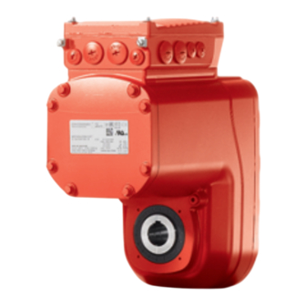
Device structure Drive unit MOVIGEAR® classic Device structure Drive unit MOVIGEAR ® classic ® Drive unit MOVIGEAR classic ® MOVIGEAR classic is a unit consisting of a gear unit and a synchronous motor in a compact aluminum die-cast housing (see following figure). MGF..4-DSM-C MGF..4-DSM-C/XT MGF..2-DSM-C... -
Page 102: Shaft Types
Device structure Shaft types Shaft types ® 6.2.1 MOVIGEAR classic with hollow shaft and keyway (MGFA..-..-C) ® The following figure shows a MOVIGEAR classic unit with hollow shaft and keyway: 9007220746621195 ® ® 6.2.2 MOVIGEAR classic with TorqLOC hollow shaft mounting system (MGFT..-..-C) ®... -
Page 103: Mounting Types Of The Housing
Device structure Mounting types of the housing Mounting types of the housing 6.3.1 Torque arm (MGF.T.-..-C) ® The following figure shows the torque arm for MOVIGEAR classic: 9007220746652683 6.3.2 Housing with threads (MGF.S-..-C) The following figure shows the housing type with threads for mounting a torque arm. This design does not include a centering shoulder, which means it is not suitable for direct installation to the system structure: 9007220746655627... -
Page 104: Threads For The Protective Cover
Device structure Threads for the protective cover Threads for the protective cover The following figure shows the threads used for fastening the protection cover: 9007220787251595 Threads for protective cover (5×) Consult SEW‑EURODRIVE before using threads for other applications. Cable entry position The device is equipped with the following cable bushings. - Page 105 Device structure Cable entry position ® 6.5.1 Overview of MOVIGEAR classic The following figure shows the possible cable entries: MGF..1-DSM-C MGF..2-DSM-C 25125407499 ® The cable bushings are identical to MOVIGEAR classic MGF..2-DSM-C for ® ® MOVIGEAR classic MGF..4-DSM-C and MOVIGEAR classic MGF..4-DSM-C/XT.
-
Page 106: Nameplate Position
Device structure Nameplate position Nameplate position ® The following nameplate positions are possible for MOVIGEAR performance and ® MOVIGEAR classic: • • • 3 (standard position) ® 6.6.1 Overview of MOVIGEAR classic The following figure shows an example of the position of the nameplates on the device: 76646 Bruchsal/Germany UL Enclosure Type 1... -
Page 107: Example Nameplate And Type Designation Of The Drive Unit
Device structure Example nameplate and type designation of the drive unit Example nameplate and type designation of the drive unit ® 6.7.1 Nameplate of MOVIGEAR classic The following figure shows an example of a drive unit nameplate. The format of the type designation can be found in chapter "Type designation ...". - Page 108 Device structure Example nameplate and type designation of the drive unit ® 6.7.2 Type designation of MOVIGEAR classic The following table shows the type designation of the drive unit. Product family ® MG = MOVIGEAR Gear unit type F = Parallel-shaft helical gear unit Shaft design A = Shaft-mounted gear unit (hollow shaft with key) ®...
-
Page 109: Connection Box And Cover
Device structure Connection box and cover Connection box and cover 6.8.1 Important notes on the terminal design ® The MOVIGEAR classic drive unit in size MGF..1-DSM-C will be delivered with a new terminal design and a modified connection assignment. The new design is also avail- able in more variants. - Page 110 Device structure Connection box and cover 6.8.2 MGF..1-DSM-C design ® The following figure shows the connection box and cover on the MOVIGEAR classic MGF..1-DSM-C: [2] [3] [4] 18014420001404043 Cable glands Connection box Terminals for internal wiring Connection board Terminals X2 for motor connection PE, W, V, U Cover Screws for PE connection Terminals X10_A for PK (Pt1000) temperature sensor...
- Page 111 Device structure Connection box and cover 6.8.3 Design MGF..1-DSM-C/DI ® The following figure shows the connection box and cover on the MOVIGEAR classic MGF..1-DSM-C/DI: [2] [3] [4] 38613976331 Cable glands Connection box Terminals for internal wiring Connection board Terminals X2_A for motor connection PE, W, V, U Cover Screws for PE connection ®...
- Page 112 Device structure Connection box and cover 6.8.4 Design MGF..1-DSM-C/DI/AZ1Z ® The following figure shows the connection box and cover on the MOVIGEAR classic MGF..1-DSM-C/AZ1Z: [2] [3] [4] [10] [1] [7] 38615476875 Cable glands Connection box Terminals for internal wiring Connection board Terminals X2_A for motor connection PE, W, V, U Cover Screws for PE connection...
- Page 113 Device structure Connection box and cover 6.8.5 MGF..2-DSM-C, MGF..4-DSM-C and MGF..4-DSM-C/XT design ® The following figure shows the connection box and the cover of MOVIGEAR classic ® MGF..2-DSM-C without MOVILINK DDI Slave and without encoder: [3] [4] [5] [4] X10_A X3_A X2_A 9007224385913739...
- Page 114 Device structure Connection box and cover 6.8.6 MGF..2-DSM-C/DI, MGF..4-DSM-C/DI and MGF..4-DSM-C/XT/DI design ® The following figure shows the connection box and the cover of MOVIGEAR classic ® MGF..2-DSM-C/DI with MOVILINK DDI Slave and without encoder: [3] [4] [5] [4] [1] [4] [7] [8] 18014424116986891 Cable glands...
- Page 115 Device structure Connection box and cover 6.8.7 MGF..2-DSM-C/DI/AZ1Z, MGF..4-DSM-C/DI/AZ1Z and MGF..4-DSM-C/XT/DI/AZ1Z design ® The following figure shows the connection box and the cover of MOVIGEAR classic ® MGF..2-DSM-C/DI/AZ1Z with MOVILINK DDI Slave and with AZ1Z encoder: [3] [4] [5] [4] [1] [4] [10] [7] [9] [8]...
-
Page 116: Example Nameplate And Type Designation Of Connection Unit
Device structure Example nameplate and type designation of connection unit Example nameplate and type designation of connection unit 6.9.1 Nameplate The following figure gives an example of a nameplate of the connection unit. For the structure of the type designation, refer to chapter "Type designation of the connection unit". -
Page 117: Markings
Device structure Markings Option ® DI = Digital Interface (MOVILINK DDI) ® CO = Digital interface (MOVILINK DDI) via coaxial element 6.10 Markings The following table shows an example of the markings on the nameplate. The CE marking indicates compliance with the following European direc- tives: •... -
Page 118: Mechanical Installation
Mechanical installation Installation notes Mechanical installation Installation notes Perform the following steps before installation: WARNING! Electric shock caused by dangerous voltages in the connection box. Severe or fatal injuries. De-energize the device. Pay attention to the 5 safety rules in chapter “Carrying out electrical work safely”. -
Page 119: Installation Requirements
Mechanical installation Installation requirements Installation requirements Check that the following conditions have been met: • The information on the drive unit's nameplate must match the voltage supply sys- tem. • The drive unit is undamaged (no damage caused by shipping or storage). •... -
Page 120: Setting Up The Drive Unit
Mechanical installation Setting up the drive unit Setting up the drive unit 7.6.1 Notes Note the following points when you assemble the drive unit: • Before setting up the drive unit, perform the steps according to chapter "Installa- tion notes" (→ 2 118). •... - Page 121 Mechanical installation Setting up the drive unit 7.6.3 Removing the cover Remove the cover as follows: 1. Let the device cool down sufficiently before touching it. 2. Loosen the screws of the cover. 3. Lever the cover off the connection box as shown in the following figure. In doing so, observe the intended positions on the figure.
- Page 122 Mechanical installation Setting up the drive unit 7.6.7 Gear unit venting Drive units with installed breather valve Except for the mounting position M3, SEW‑EURODRIVE delivers all drive units ordered for a specific mounting position with a breather valve that is activated and in- stalled according to the specific mounting position.
- Page 123 Mechanical installation Setting up the drive unit Mounting the breather valve in mounting position M1 The following figure shows an example of how to mount the breather valve in mount- ing position M1: Example: Mounting position M1 18014420871415435 ® Product Manual – MOVIGEAR classic...
- Page 124 Mechanical installation Setting up the drive unit Activating the breather valve For designs with screwed-in breather valve, check whether the breather valve is acti- vated. If not, you have to remove the transport protection of the breather valve before you start up the drive unit. Activate the breather valve as follows: 1.
- Page 125 Mechanical installation Setting up the drive unit 7.6.8 Pressure compensation on electronics (option /PE) Fitting the provided pressure compensation fitting (option/PE) For designs with an included pressure compensation fitting (option /PE), install the fit- ting depending on the mounting position used. The tightening torque is 4.0 Nm. Pressure compensation fitting installation positions The following table shows the installation location-dependent mounting positions of the pressure compensation fitting (option/PE):...
-
Page 126: Shaft-Mounted Gear Unit With Keyway
Mechanical installation Shaft-mounted gear unit with keyway Shaft-mounted gear unit with keyway INFORMATION Concerning the customer shaft design, refer to the design notes in the product manual > chapter "Technical data". INFORMATION To avoid contact corrosion, SEW‑EURODRIVE recommends that the customer shaft should additionally be lathed down between the 2 contact surfaces! 7.7.1 Mounting the drive unit... -
Page 127: Customer Shaft With Contact Shoulder
Mechanical installation Shaft-mounted gear unit with keyway 5. The 3 installation types are described below: ð 3A: Standard scope of delivery 9007220768364043 Short retaining screw (standard scope of delivery) Lock washer Washer Retaining ring Customer shaft ð 3B: Assembly/disassembly kit for customer shaft with contact shoulder. Ob- serve the information in the product manual >... - Page 128 Mechanical installation Shaft-mounted gear unit with keyway 9007220768369931 Retaining screw Lock washer Washer Retaining ring Spacer tube Customer shaft without contact shoulder 6. Tighten the retaining screw with the specified torque (see following chapter "Tight- ening torques for retaining screws"). 9007220768463371 7.7.2 Retaining screw tightening torques...
- Page 129 Mechanical installation Shaft-mounted gear unit with keyway 7.7.3 Disassembly notes INFORMATION Information regarding the SEW‑EURODRIVE assembly/disassembly kit can be found in the product manual > chapter "Design notes for gear units with hollow shaft and key" (→ 2 65). The following description only applies when the drive is assembled using the SEW‑EURODRIVE assembly/disassembly kit (see previous description, points 2B or 2C).
- Page 130 Mechanical installation Shaft-mounted gear unit with keyway 6. Re-insert the retaining ring [4]. 7. Screw in the retaining screw [1] again. You can now force the drive from the shaft by tightening the screw. 9007220768469259 Retaining screw Retaining ring Customer shaft Fixed nut Forcing washer ®...
- Page 131 Mechanical installation Shaft-mounted gear unit with TorqLOC® (customer shaft without contact shoulder) Shaft- mounted gear unit with TorqLOC® (customer shaft without contact shoulder) ® Shaft-mounted gear unit with TorqLOC (customer shaft without contact shoulder) Mount the drive unit on the shaft as follows: 1.
- Page 132 Mechanical installation Shaft-mounted gear unit with TorqLOC® (customer shaft without contact shoulder) 5. Apply NOCO‑Paste onto the bushing and spread it carefully. 9007220783646731 6. Slide the gear unit onto the customer shaft. 9007220783649163 7. Mount the torque arm onto the system structure/holding fixture (do not tighten the screws).
- Page 133 Mechanical installation Shaft-mounted gear unit with TorqLOC® (customer shaft without contact shoulder) 8. Slide the bushing into the gear unit as far as its stop. 9007220783654027 9. Slide the stop ring onto the bushing. Mark the position of the stop ring. 9007220783656459 ®...
- Page 134 Mechanical installation Shaft-mounted gear unit with TorqLOC® (customer shaft without contact shoulder) 10. Remove the torque arm from the holding fixture/system structure. 9007220783658891 11. Remove the gear unit from the customer shaft until the stop ring is accessible for installation. 9007220783661323 12.
- Page 135 Mechanical installation Shaft-mounted gear unit with TorqLOC® (customer shaft without contact shoulder) 18014420037795339 14. Slide the bushing and the gear unit onto the customer shaft up to the fixed stop ring. 9007220783619979 15. Mount the torque arm onto the system structure/holding fixture again (do not tighten the screws).
- Page 136 Mechanical installation Shaft-mounted gear unit with TorqLOC® (customer shaft without contact shoulder) 16. Make sure that all screws are loosened and slide the shrink disk onto the hollow shaft. 18014420038365835 17. Slide the counter bushing onto the customer shaft and into the hollow shaft. 27021619293109259 18.
- Page 137 Mechanical installation Shaft-mounted gear unit with TorqLOC® (customer shaft without contact shoulder) 20. Make sure that the customer shaft is seated in the counter bushing. 18014420038373131 21. Tighten the screws of the shrink disk only hand-tight and make sure that the outer rings of the shrink disk are plane-parallel.
- Page 138 Mechanical installation Shaft-mounted gear unit with TorqLOC® (customer shaft without contact shoulder) 23. After installation, make sure the remaining gap s between the outer rings of the shrink disks is > 0 mm. ð The remaining gap between the counter bushing and hollow shaft end, as well as the bushing and stop ring must be > 0 mm.
- Page 139 Mechanical installation Shaft-mounted gear unit with TorqLOC® (customer shaft with contact shoulder) Shaft- mounted gear unit with TorqLOC® (customer shaft with contact shoulder) ® Shaft-mounted gear unit with TorqLOC (customer shaft with contact shoulder) Mount the drive unit on the shaft as follows: 1.
- Page 140 Mechanical installation Shaft-mounted gear unit with TorqLOC® (customer shaft with contact shoulder) 4. Mount the bushing on the customer shaft. 0 mm 21528993931 5. Apply NOCO‑Paste onto the bushing and spread it carefully. 9007220783737355 6. Slide the gear unit onto the customer shaft. 9007220783739787 ®...
- Page 141 Mechanical installation Shaft-mounted gear unit with TorqLOC® (customer shaft with contact shoulder) 7. Make sure that all screws are loosened and slide the shrink disk onto the hollow shaft. 18014420038483211 8. Slide the counter bushing onto the customer shaft and into the hollow shaft. 27021619293226635 9.
- Page 142 Mechanical installation Shaft-mounted gear unit with TorqLOC® (customer shaft with contact shoulder) 11. Make sure that the customer shaft is seated in the counter bushing. 18014420038490507 12. Tighten the screws of the shrink disk only hand-tight and make sure that the outer rings of the shrink disk are plane-parallel.
- Page 143 Mechanical installation Shaft-mounted gear unit with TorqLOC® (customer shaft with contact shoulder) 15. The remaining gap between the counter bushing and hollow shaft end must be > 0 mm. > 0 mm > 0 mm 21528986635 16. Mount the torque arm and tighten it firmly. Observe chapter "Torque arm" (→ 2 147).
-
Page 144: Shaft-Mounted Gear Unit With Torqloc - Disassembly, Cleaning, Lubrication
Mechanical installation Shaft-mounted gear unit with TorqLOC® – disassembly, cleaning, lubrication Shaft- mounted gear unit with TorqLOC® – d isassembl y, cleaning, lubrication ® 7.10 Shaft-mounted gear unit with TorqLOC – disassembly, cleaning, lubrication 7.10.1 Removing the drive unit Remove the drive unit from the shaft as follows: 1. - Page 145 Mechanical installation Shaft-mounted gear unit with TorqLOC® – disassembly, cleaning, lubrication 7.10.2 Cleaning and lubrication There is no need to dismantle removed shrink discs before they are reinstalled. 1. Clean and lubricate the shrink disk if it is dirty. 2. Lubricate the tapered surfaces with one of the following solid lubricants: Lubricant (Mo S2) Sold as Molykote 321 (lube coat)
-
Page 146: Installing The Protective Cover
Mechanical installation Installing the protective cover 7.11 Installing the protective cover 7.11.1 Installing the fixed safety cover NOTICE Damage to the drive unit due to improper use of the threads. Damage to property. • Consult SEW‑EURODRIVE before using threads for other applications. Install the safety cover as follows: 1. -
Page 147: Torque Arm
Mechanical installation Torque arm 7.11.2 Installation without cover In certain individual cases (e.g. through-shaft), you cannot install the safety cover. In these cases, the safety cover is not necessary if the system or unit manufacturer provides corresponding components to guarantee for the compliance with the required degree of protection. - Page 148 Mechanical installation Torque arm 7.12.1 Installation options The following figure shows the possible mounting positions of the torque arm: 9007220778895883 Torque arm axis length Bore diameter Torque arm thickness Bush with bearings on both ends The following table shows the required tightening torques: Drive Torque arm Tightening torque...
-
Page 149: Tightening Torques
Mechanical installation Tightening torques 7.13 Tightening torques ® 7.13.1 Example of MOVIGEAR classic The following figure shows an example of the installation of the threaded blanking plugs, cable glands, and electronics cover. The number and position of threaded blanking plugs and cable bushings depend on the ordered variant. 38411571979 Tighten the screws step by step in a diametrically opposite sequence with a tightening torque of 6.0 Nm. - Page 150 Mechanical installation Tightening torques 7.13.2 Tightening torques for cable glands Tighten cable glands optionally included delivery SEW‑EURODRIVE with the following torques: Screw fitting type Image Con- Size Tightening Outer Tight- Part num- tent torque diame- ening ter of force Thread Cable cable clamp-...
-
Page 151: Electrical Installation
Electrical installation Equipotential bonding Electrical installation Equipotential bonding INFORMATION For gearmotors in hollow-shaft design, additional HF-capable equipotential bonding can be required independent of the mandatory PE connection. For this kind of drive (hollow shaft), high-frequency currents (e.g. by frequency inverters) are not ideally discharged to the system structure. -
Page 152: Equipotential Bonding At The Connection Box
Electrical installation Equipotential bonding at the connection box Equipotential bonding at the connection box The following cable gland with an M6 threaded bolt provides an additional option for HF-compatible equipotential bonding on a connection box: 9007203139701899 Tightening torque Part number Cable gland M6 nut for stud bolt... - Page 153 Electrical installation Installation instructions 8.3.2 Permitted cable cross section of terminals Terminals X2 for motor connection Observe the permitted cable cross section for installation: Terminals X2 for motor connection Connection cross sec- 0.5 mm – 6.0 mm tion Stripping length 11 mm – 12 mm Terminals X2_A for motor connection Observe the permitted cable cross sections for installation: Terminals X2_A...
- Page 154 Electrical installation Installation instructions 8.3.3 Activating terminals X2 for motor connection Adhere to the following sequence when activating the terminals X2 for motor connec- tion: 22904853003 8.3.4 Activating terminals X2_A for the motor connection Adhere to the following sequence when activating the terminals X2_A for motor con- nection: 25663071627 ®...
- Page 155 Electrical installation Installation instructions 8.3.5 Activating terminals X4 for temperature sensor Adhere to the following sequence when activating the terminals X4 for the temperature sensor: Connect conductor, Connect conductor, without pressing the activation button. after pressing the activation button. 22904860811 22904932619 The following conductors can be installed When connecting the following conduc-...
- Page 156 Electrical installation Installation instructions 8.3.6 Activating terminals X10_A for the temperature sensor Adhere to the following sequence when activating the terminals X10_A for the temper- ature sensor: Connect conductor, Connect conductor, without pressing the activation button. after pressing the activation button. 22904860811 22904932619 The following conductors can be installed...
- Page 157 Electrical installation Installation instructions 8.3.7 Notes on PE connection ® PE connection to MOVIGEAR with lifting eye The handle is only used to transport the unit. The handle is not required for operation. 1. Remove the lifting eye. Store the lifting eye for future service work. 2.0 –...
-
Page 158: Installation Topologies
Electrical installation Installation topologies Installation topologies ® 8.4.1 Installation topology with MOVIMOT flexible ® The following figure shows a basic installation topology with MOVIMOT flexible de- centralized drive electronics. Observe the installation notes in the documentation of the inverter that you use. Control cabinet level Field level MGF..1-DSM-C... - Page 159 Electrical installation Installation topologies ® ® 8.4.2 Installation topology with MOVITRAC LTP-B, LTE-B+ and MOVI‑PLC with CCU The following figure shows a schematic installation topology with the frequency in- ® ® verter MOVITRAC LTP-B, LTE-B+, SEW‑EURODRIVE controller MOVI‑PLC with ® CCU and MOVIGEAR classic..
- Page 160 Electrical installation Installation topologies ® ® 8.4.3 Installation topology with MOVIDRIVE and MOVI-C CONTROLLER ® The following figure shows a schematic installation topology with the MOVIDRIVE ® ® modular application inverter, MOVIDRIVE system, MOVI-C CONTROLLER, and ® MOVIGEAR classic by SEW‑EURODRIVE. Observe the installation notes in the documentation of the inverter/controller that you use.
-
Page 161: Terminal Assignment Movigear Classic
Electrical installation Terminal assignment of MOVIGEAR® classic Terminal assignment of MOVIGEAR ® classic ® Terminal assignment MOVIGEAR classic 8.5.1 Terminal assignment for MGF..1-DSM-C Observe the wiring instructions in the documentation of the frequency inverter that you use. Attach units without a connector to the terminals as follows: ... - Page 162 Electrical installation Terminal assignment of MOVIGEAR® classic 8.5.2 Terminal assignment MGF..1-DSM-C/DI Observe the wiring instructions in the documentation of the frequency inverter that you use. Attach units without a connector to the terminals as follows: WARNING! Electric shock caused by dangerous voltages in the connection box.
- Page 163 Electrical installation Terminal assignment of MOVIGEAR® classic 8.5.3 Terminal assignment MGF..1-DSM-C/DI/AZ1Z Observe the wiring instructions in the documentation of the frequency inverter that you use. Attach units without a connector to the terminals as follows: WARNING! Electric shock caused by dangerous voltages in the connection box.
- Page 164 Electrical installation Terminal assignment of MOVIGEAR® classic 8.5.4 Terminal assignment MGF..2-DSM-C, MGF..4-DSM-C and MGF..4-DSM-C/XT Observe the wiring instructions in the documentation of the frequency inverter that you use. Attach units without a connector to the terminals as follows: WARNING! Electric shock caused by dangerous voltages in the connection box.
- Page 165 Electrical installation Terminal assignment of MOVIGEAR® classic 8.5.5 Terminal assignment MGF..2-DSM-C/DI, MGF..4-DSM-C/DI and MGF..4-DSM-C/XT/DI Observe the wiring instructions in the documentation of the frequency inverter that you use. Attach units without a connector to the terminals as follows: WARNING! Electric shock caused by dangerous voltages in the connection box.
- Page 166 Electrical installation Terminal assignment of MOVIGEAR® classic Terminal Name Marking Function X3_A Pink Reserved Res. – Reserved Orange Reserved ® X16_A DDI inter- – MOVILINK DDI interface face The terminal assignment also applies to MGF..4‑DSM-C/DI and MGF..4‑DSM-C/XT/ ® Product Manual – MOVIGEAR classic...
- Page 167 Electrical installation Terminal assignment of MOVIGEAR® classic 8.5.6 Terminal assignment MGF..2-DSM-C/DI/AZ1Z, MGF..4-DSM-C/DI/AZ1Z and MGF..4-DSM-C/ XT/DI/AZ1Z Observe the wiring instructions in the documentation of the frequency inverter that you use. Attach units without a connector to the terminals as follows: WARNING! Electric shock caused by dangerous voltages in the connection box.
-
Page 168: Thermal Motor Protection
Electrical installation Thermal motor protection Terminal Name Marking Function X3_A Pink Reserved Res. – Reserved Orange Reserved ® X16_A – MOVILINK DDI interface ® MOVILINK interface The terminal assignment also applies to MGF..4‑DSM-C/DI/AZ1Z and MGF..4‑DSM- C/XT/DI/AZ1Z. Thermal motor protection ® Some MOVIGEAR designs have a temperature sensor to protect them from over- heating. - Page 169 Electrical installation Thermal motor protection 8.6.1 PK temperature sensor (Pt1000) If required, you can check the resistance of the PK temperature sensor. 1. Connect the measuring contacts of the test device to the terminals of the tempera- ® ture sensor in accordance with chapter "Terminal assignment of MOVIGEAR classic" (→ 2 161).
-
Page 170: Bulk Cable
Electrical installation Bulk cable Bulk cable 8.7.1 Brake motor cables for motors without digital interface Connection cable 1.5 mm The following table shows the available connection cables: Connection cables Conformity/ Cable reel/in- Cable type/ Cable cross Operating stallation type properties section/ voltage Part number... - Page 171 Electrical installation Bulk cable Connection of bulk cables The following table shows the core assignment of cables with the following part num- bers: Part numbers Installation method of cable Part numbers 19150067, 19150075 Connection description Bulk cable Motor connection depending on brake control Without brake Conductor Identifi-...
- Page 172 Electrical installation Bulk cable ® 8.7.2 Brake motor cables for motors with digital interface (MOVILINK DDI) Connection cable 1.5 mm The following table shows the available connection cables: Connection cable Conformity/ Cable reel/in- Cable type/ Cable cross Operating stallation type properties section/ voltage...
- Page 173 Electrical installation Bulk cable Connection cable 2.5 mm The following table shows the available connection cables: Connection cable Conformity/ Cable reel/in- Cable type/ Cable cross Operating stallation type properties section/ voltage Part number ® Motor connection CE/UL: 50 m LEONI LEHC 2.5 mm ®...
- Page 174 Electrical installation Bulk cable Connection of bulk cables The following table shows the core assignment of cables with the following part num- bers: Part numbers Installation method of cable Part numbers 28123336, 28123344 28123395, 28123409 Connection description Bulk cable Motor connection depending on brake control Without brake Conductor Identifi-...
-
Page 175: Connectors
Electrical installation Connectors Connectors 8.8.1 Representation of connections The connection diagrams of the connectors depict the contact end of the connections. 8.8.2 Connection cables INFORMATION For more information about cable types, see chapter "Technical data". Connection cables are not included in the scope of delivery. Prefabricated cables for connecting SEW‑EURODRIVE components are available to order. - Page 176 Electrical installation Connectors Cable routing Observe the permitted bending radii of the cables used when routing the cables. Fur- ther information can be found in the product manual > chapter "Technical data" > "Di- mension drawings of connectors of the connection box" > "Connectors including mat- ing connectors".
- Page 177 Electrical installation Connectors ® 8.8.3 Connector positions at MOVIGEAR classic MGF..1-DSM-C The following figure shows possible connector positions: X2111 X2040 X2040 18014424216082315 Connector Designation Coding ring Function Position color X2040 Without cod- "Connection of standard mo- X or 2 ing ring tor" (→ 2 181), option /KH1 X2111...
- Page 178 Electrical installation Connectors ® 8.8.4 Connector positions MOVIGEAR classic MGF..2-DSC-C, MGF..4-DSC-C, MGF..4-DSC-C/XT The following figure shows possible connector positions: X2111 X2111 X2040 X2040 X2111 X2040 27021622981487115 Connector Designation Coding ring Function Position color X2040 Without cod- "Connection of standard mo- X, 2 or 3 ing ring tor" (→ 2 181),...
- Page 179 Electrical installation Connectors 8.8.5 Connector variants M23 connector The M23 connectors are available in the following variants: • [1] "Straight" connector • [2] "Angled" connector After plugging in the mating connector, you can align the angled connector without the need for additional tools. Observe the following notes: •...
- Page 180 Electrical installation Connectors 8.8.6 Using connectors assembled by yourself M23 connector by TE connectivity – Intercontec Products The power connectors for assembling connection cables yourself, and the correspond- ing assembly tool set is available for order from TE Connectivity - Intercontec products.
-
Page 181: Optional Connector Assignment
Electrical installation Optional connector assignment Optional connector assignment For the positions of the connectors, refer to chapter "Connector positions.." . 8.9.1 X2040 (Option /KH1): Motor connection for standard motors with temperature sensor The following table provides information about this connection: Function Motor connection for standard motors with temperature probe Connection type M23, male, male thread, TE Connectivity –... - Page 182 Electrical installation Optional connector assignment Connection cables Cable cross section 1.5 mm The following table shows the cables available for this connection: Connection cable Conformity/ Cable type Length/in- Cable part num- stallation cross sec- type tion/operat- ing voltage ® CE/UL: LEONI LEHC Variable 1.5 mm 005272...
- Page 183 Electrical installation Optional connector assignment Cable cross section 2.5 mm The following table shows the cables available for this connection: Connection cable Conformity/ Cable type Length/in- Cable part num- stallation cross sec- type tion/operat- ing voltage ® CE/UL: LEONI LEHC Variable 2.5 mm 005275 28128443...
- Page 184 Electrical installation Optional connector assignment Connection of cables with open end The following table shows the core assignment of cables with the following part num- bers: Part numbers 18191290, 18191304 Assembly Open cable end Motor connection depending on brake con- Prefabricated con- trol nector...
- Page 185 Electrical installation Optional connector assignment Assembly Open cable end Motor connection depending on brake con- Prefabricated con- trol nector Without brake Con- Identifi- Assembly Description Signal Contact ductor cation color/ core cross section Gray Not pre- Reserved 0.34 mm fabricated Pink 0.34 Not pre- Reserved fabricated...
- Page 186 Electrical installation Optional connector assignment ® 8.9.2 X2111 (Option /KD1): Motor connection for motors with digital interface (MOVILINK DDI) The following table provides information about this connection: Function ® Motor connection for motors with digital interface (MOVILINK DDI) Connection type M23, male, male thread, TE Connectivity –...
- Page 187 Electrical installation Optional connector assignment Connection cables Cable cross section 1.5 mm The following table shows the cables available for this connection: Connection cable Conformity/ Cable type Length/in- Cable part num- stallation cross sec- type tion/operat- ing voltage ® CE/UL: LEONI LEHC Variable 1.5 mm 005769...
- Page 188 Electrical installation Optional connector assignment Cable cross section 2.5 mm The following table shows the cables available for this connection: Connection cable Conformity/ Cable type Length/in- Cable part num- stallation cross sec- type tion/operat- ing voltage ® CE/UL: LEONI LEHC Variable 2.5 mm 005770 28123751...
- Page 189 Electrical installation Optional connector assignment Connection of cables with open end The following table shows the core assignment of cables with the following part num- bers: Part numbers 28105818, 18191541, 28105826, 18191568 Assembly Open cable end Motor connection depending on brake control Prefabricated con- nector Without...
- Page 190 Electrical installation Optional connector assignment Assembly Open cable end Motor connection depending on brake control Prefabricated con- nector Without 3-wire 2-wire Brake Brake brake brake brake rectifier rectifier AC 110- DC 24 500 V (BE/BZ BK/BP BGI500 BGI24 brake) brake Con- Identifi- Assembly Description Signal Contact...
-
Page 191: Startup
Startup Startup notes Startup Startup notes INFORMATION • Correct project planning for the drive is a prerequisite for successful startup. See chapter "Project Planning" for more information. • The motor speed must not exceed 2000 min . Set the maximum speed on the fre- quency inverter. -
Page 192: Startup Requirements
Startup Startup requirements Startup requirements 9.2.1 Before startup Make sure the following requirements are met before startup: • The drive unit is undamaged and not blocked. • The measures stipulated in chapter "Extended storage of motors" are performed after extended storage periods. •... -
Page 193: Service
Service Malfunctions of the mechanical drive Service NOTICE Improper work on the drive units can result in damage. Damage to property. • Make sure that the drives from SEW‑EURODRIVE are repaired by qualified per- sonnel only. • Consult SEW‑EURODRIVE SERVICE. 10.1 Malfunctions of the mechanical drive The following table shows troubleshooting options for malfunctions of the mechanical... - Page 194 Service Malfunctions of the mechanical drive Fault Possible cause Measure Oil leaking from the out- Drive installed in the wrong Install the breather valve put-side oil seal mounting position or correctly breather valve installed in wrong position. Short-term oil and/or grease leakage at the oil seal is possible in the run- in phase (24 hours running...
-
Page 195: Device Replacement
Service Device replacement Fault Possible cause Measure Drive unit heats up ex- Frequency inverter not op- Check frequency inverter cessively (measure tem- timized perature, significantly higher than 100 °C) 10.2 Device replacement 10.2.1 Replacing the drive unit Replace the drive unit as follows: 1. - Page 196 Service Device replacement 10.2.2 Installing the handle Install the handle as follows: 1. Remove the PE connection cable. 2. Install the handle for transportation as depicted in the following image: INFORMATION The following figure shows an example of the handle. Different designs are used de- pending on the size.
-
Page 197: Sew-Eurodrive Service
If a fault cannot be repaired, contact SEW‑EURODRIVE Service, see chapter "Con- tacting SEW-EURODRIVE" (→ 2 216). Always specify the digits of the status label when contacting the SEW-EURODRIVE electronics service team. This will enable our Service personnel to assist you more ef- fectively. -
Page 198: Storage
Service Storage 10.5 Storage Observe the following information when shutting down or storing the device: • If you shut down and store the device for a longer period, you must close open cable bushings and cover contacts with protection caps. •... - Page 199 Service Extended storage 10.6.2 Storage conditions Observe the storage conditions listed in the following table with respect to extended storage: Climate zone Packaging Storage location Storage period Temperate Packaged in contain- Under roof, protection against rain and Up to 3 years with regu- (Europe, USA, ers, with desiccant snow, vibration-free.
-
Page 200: Waste Disposal
Service Waste disposal 10.7 Waste disposal Dispose of the product and all parts separately in accordance with their material struc- ture and the national regulations. Put the product through a recycling process or con- tact a specialist waste disposal company. If possible, divide the product into the follow- ing categories: •... -
Page 201: Inspection And Maintenance
Inspection and maintenance Inspection and maintenance intervals Inspection and maintenance 11.1 Inspection and maintenance intervals The following table shows the inspection and replacement intervals for the drive units: Time interval What should I do? Who is permitted to perform the work? Every 3000 operating Check running noise for possible Specialists at cus-... - Page 202 Inspection and maintenance Inspection and maintenance intervals Time interval What should I do? Who is permitted to perform the work? When the cover/elec- When the cover/electronics cover Specialists at cus- tronics cover is opened is opened after an operating tomer site after an operating period of ≥ 6 months, the gasket period of ≥ 6 months...
-
Page 203: Lubricant Change Intervals
Inspection and maintenance Lubricant change intervals 11.2 Lubricant change intervals The following figure shows the lubricant change intervals for normal ambient condi- tions. In case of severe/aggressive ambient conditions, the lubricant must be changed more frequently: 30000 25000 20000 15000 10000 5000 [°C]... - Page 204 Inspection and maintenance Inspection and maintenance work 11.3.2 Changing the oil Draining the oil The gear unit cover may only be opened by the SEW‑EURODRIVE Service team or specialists trained by SEW‑EURODRIVE. 1. Perform the steps according to chapter "Preliminary work regarding inspection and maintenance".
- Page 205 Inspection and maintenance Inspection and maintenance work Filling in the oil The gear unit cover may only be opened by the SEW‑EURODRIVE Service team or specialists trained by SEW‑EURODRIVE. 1. Perform the steps described in the chapter "Preliminary work for inspection and maintenance".
- Page 206 Inspection and maintenance Inspection and maintenance work 11.3.3 Replacing the output oil seal 1. Perform the steps according to chapter "Preliminary work regarding inspection and maintenance". 2. Remove the drive unit from the system. 3. NOTICE! If oil seals are below 0 °C, they can be damaged during assembly. Dam- age to property.
- Page 207 Inspection and maintenance Inspection and maintenance work 11.3.7 Replacing the gasket between connection box and cover Spare part kit The gasket is available as a spare part (1, 10 or 50 pieces) from SEW‑EURODRIVE. Content Part number of gasket ® ® MOVIGEAR classic MOVIGEAR...
- Page 208 Inspection and maintenance Inspection and maintenance work 2. Loosen the screws of the cover and remove it. 9007220768475147 ® Product Manual – MOVIGEAR classic...
- Page 209 Inspection and maintenance Inspection and maintenance work 3. NOTICE! Loss of the guaranteed degree of protection. Possible damage to prop- erty. Make sure that the sealing surfaces are not damaged when removing the gasket. Remove the old gasket completely from the connection box. 21514108299 ...
- Page 210 Inspection and maintenance Inspection and maintenance work 5. Place the new gasket on the connection box and fix it in position with the retaining cams [1]. 22361594123 Retaining cams ® Product Manual – MOVIGEAR classic...
- Page 211 Inspection and maintenance Inspection and maintenance work 6. Check the installation and startup of the drive unit based on the applicable operat- ing instructions. 7. Place the cover back onto the connection box and secure it. ð Proceed as follows when installing the cover: Insert/screw in the screws and tighten them step by step in diametrically opposite sequence with a tightening torque of 6.0 Nm.
- Page 212 Inspection and maintenance Inspection and maintenance work ® Work steps for MOVIGEAR classic MGF..2-..C and MGF..4-..C NOTICE Loss of the guaranteed degree of protection. Damage to property. • When the cover is removed from the connection box, the cover and the wiring space must be protected from humidity, dust or foreign particles.
- Page 213 Inspection and maintenance Inspection and maintenance work 3. NOTICE! Loss of the guaranteed degree of protection. Damage to property. Make sure that the sealing surfaces are not damaged when removing the gasket. Loosen the used gasket by levering it off the retaining cams. ð...
- Page 214 Inspection and maintenance Inspection and maintenance work CAUTION! Risk of injury due to sharp edges. Cutting injuries. Use protective gloves when cleaning. Ensure that work is carried out by trained specialists only. Carefully clean the sealing surfaces of the connection box and the cover. 54669725195 6.
- Page 215 Inspection and maintenance Inspection and maintenance work 7. Check the installation and startup of the drive unit based on the applicable operat- ing instructions. 8. Place the cover back onto the connection box and secure it. ð Proceed as follows when installing the cover: Insert/screw in the screws and tighten them step by step in diametrically opposite sequence with a tightening torque of 6.0 Nm.
-
Page 216: Contacting Sew-Eurodrive
Contacting SEW-EURODRIVE Contacting SEW-EURODRIVE You can find the worldwide contact data and locations on the SEW‑EURODRIVE website via the following link or the QR code shown below. https://www.sew-eurodrive.de/contacts-worldwide ® Product Manual – MOVIGEAR classic... -
Page 217: Index
Index Index Cover .......... 110, 111, 112 Current, permitted .......... 32 Air admission and accessibility...... 25 Ambient temperature ........... 27 Assembly Decimal separator.......... 8 Safety notes ........... 13 Design information .......... 65 Shaft-mounted gear units with keyway.. 126 Device replacement ........... 195 AZ1Z.............. 37 Device structure Cable bushing position ......... 104 Connection box...... 110, 111, 112 Breather valve... - Page 218 Index Hazard symbols Lubricant change intervals ......... 203 Meaning............ 7 Lubricants ............ 56 Hollow shaft with keyway (MGFA..)..... 65, 126 Bearing greases.......... 56 Housing mounting .......... 103 Compatibility with oil seal........ 60 Torque arm (MGF.T.-..-C) ...... 103 Fill quantities........... 57 Housing mounting types Information............ 59 Housing with threads (MGF.S-..-C) .... 103 Key.............. 61 Lubricant table .......... 62 Identification, nameplate ........
- Page 219 Index Options Service /AZ1Z.............. 37 Device replacement ........ 195 Extended storage.......... 198 Malfunctions of the mechanical drive.... 193 Painting ............ 25, 206 SEW‑EURODRIVE Service ...... 197 PE connection ........... 157 Setting up the drive unit ........ 120 PK (Pt1000) ............ 29 SEW-Workbench .......... 90 Characteristic curve........ 29, 169 Shaft designs Connection ...........
- Page 220 Index Surface protection .......... 43 Temperature sensor .......... 169 Unit structure Terminal actuation ...... 154, 155, 156 Housing mounting......... 103 Terminal assignment ......... 161 Nameplate and type designation of the drive unit Thermal motor protection ...... 152, 168 .............. 107 Tightening torque Nameplate position ........ 106 Friction coefficient ........
- Page 224 SEW-EURODRIVE—Driving the world SEW-EURODRIVE GmbH & Co KG Ernst-Blickle-Str. 42 76646 BRUCHSAL GERMANY Tel. +49 7251 75-0 Fax +49 7251 75-1970 sew@sew-eurodrive.com www.sew-eurodrive.com...
Need help?
Do you have a question about the MOVIGEAR classic MGF -DSM-C Series and is the answer not in the manual?
Questions and answers