SEW-Eurodrive MOVIMOT advanced DRN DBC Series Product Manual
Hide thumbs
Also See for MOVIMOT advanced DRN DBC Series:
- Operating instructions manual (312 pages) ,
- Product manual (520 pages)

Related Manuals for SEW-Eurodrive MOVIMOT advanced DRN DBC Series


Summary of Contents for SEW-Eurodrive MOVIMOT advanced DRN DBC Series
- Page 1 *27803953_0223* Drive Technology \ Drive Automation \ System Integration \ Services Product Manual Mechatronic Drive Unit ® MOVIMOT advanced DRN..DBC.., DR2C..DBC.. (Binary) Edition 02/2023 27803953/EN...
- Page 2 SEW-EURODRIVE—Driving the world...
-
Page 3: Table Of Contents
Table of Contents Table of Contents General information........................ 6 About this documentation .................... 6 Other applicable documentation .................. 6 Structure of the safety notes ................... 6 Decimal separator in numerical values ................ 8 Rights to claim under limited warranty ................ 8 Recycling und re-use ...................... 8 Product names and trademarks.................. 8 Copyright notice ...................... 8 ®... - Page 4 Table of Contents Preliminary information .................... 132 SEW-Workbench ...................... 132 Data for drive selection/designation................ 132 ® MOVIMOT advanced .................... 135 Thermal motor protection without temperature sensor .......... 147 UL-compliant installation..................... 149 Project planning for functional safety ................ 151 General information .................... 151 Integrated safety technology.................. 152 Safety conditions...................... 157 Connections variants .................... 162 Safety characteristics.................... 164 Device structure ........................
- Page 5 Table of Contents Startup ........................... 284 10.1 Startup notes....................... 284 10.2 Startup requirements .................... 285 10.3 Parameterization mode.................... 286 10.4 Control elements...................... 287 10.5 DIP switches ....................... 290 10.6 Startup procedure ....................... 294 10.7 Startup with CBG22A on-site keypad ................. 296 10.8 Startup with the CBG21A keypad ................ 299 10.9 Startup with the CBG11A keypad ................ 301 10.10...
-
Page 6: General Information
General information About this documentation General information About this documentation The documentation at hand is the original. This documentation is an integral part of the product. The documentation is intended for all employees who perform work on the product. Make sure this documentation is accessible and legible. Ensure that persons respon- sible for the systems and their operation as well as persons who work on the product independently have read through the documentation carefully and understood it. - Page 7 General information Structure of the safety notes 1.3.2 Structure of section-related safety notes Section-related safety notes do not apply to a specific action but to several actions pertaining to one subject. The hazard symbols used either indicate a general hazard or a specific hazard.
-
Page 8: Decimal Separator In Numerical Values
General information Decimal separator in numerical values Decimal separator in numerical values In this document, a period is used to indicate the decimal separator. Example: 30.5 kg Rights to claim under limited warranty Read the information in this documentation. This is essential for fault-free operation and fulfillment of any rights to claim under limited warranty. -
Page 9: Safety Notes For Movimot Advanced
® Safety notes for MOVIMOT advanced Preliminary information ® Safety notes for MOVIMOT advanced Preliminary information The following general safety notes serve the purpose of preventing injury to persons and damage to property. They primarily apply to the use of products described in this documentation. -
Page 10: Target Group
® Safety notes for MOVIMOT advanced Target group Target group Specialist for me- Any mechanical work may be performed only by adequately qualified specialists. Spe- chanical work cialists in the context of this documentation are persons who are familiar with the design, mechanical installation, troubleshooting, and maintenance of the product, and who possess the following qualifications: •... -
Page 11: Designated Use
Do not use the product as a climbing aid. 2.5.1 Restrictions under the European WEEE Directive 2012/19/EU Options and accessories from SEW-EURODRIVE may only be used in combination with products from SEW-EURODRIVE. 2.5.2 Hoist applications To avoid danger of fatal injury by falling hoists, observe the following points when us- ing the product in lifting applications: •... -
Page 12: Functional Safety Technology
® Safety notes for MOVIMOT advanced Functional safety technology • Use in areas exposed to harmful oils, acids, gases, vapors, dust, and radiation. • Operation in applications with impermissibly high mechanical vibration and shock loads in excess of the regulations stipulated in EN 61800-5-1. •... -
Page 13: Transportation
® Safety notes for MOVIMOT advanced Transportation Transportation Inspect the shipment for damage as soon as you receive the delivery. Inform the ship- ping company immediately about any damage. If the product or the packaging is dam- aged, do not assemble, install, connect, or start up the product. If the packaging is damaged, the product itself may also be damaged. -
Page 14: Creating A Safe Working Environment
® Safety notes for MOVIMOT advanced Creating a safe working environment Creating a safe working environment Before you work on the product, ensure a safe working environment. Observe the fol- lowing basic safety note: 2.8.1 Performing work on the product safely Defective or dam- Never install defective or damaged products. - Page 15 ® Safety notes for MOVIMOT advanced Creating a safe working environment 2.8.2 Performing electrical work safely Observe the following information to perform electrical work safely: Electrical work may only be performed by a qualified electrician or an electronically in- structed person under the supervision of an electrician. Observe the 5 safety rules in the specified sequence when working on electrical com- ponents, unless there are important reasons to deviate from them (observe the specifi- cations of DIN EN 50110-1 (VDE 0115-1)):...
-
Page 16: Installation/Assembly
® Safety notes for MOVIMOT advanced Installation/assembly Installation/assembly Ensure that the product is installed and cooled in accordance with the regulations in the documentation. Protect the product from excessive mechanical strain. The product and its mounted components must not protrude into the path of persons or vehicles. Ensure that no components are deformed or no insulation spaces are modified, particularly during transportation. -
Page 17: Electrical Installation
® Safety notes for MOVIMOT advanced Electrical installation 2.11 Electrical installation The preventive measures and protection devices must comply with the applicable reg- ulations (e.g. EN 60204-1 or EN 61800-5-1). 2.11.1 Stationary application The necessary preventive measure for the product is: Type of energy transfer Preventive measure Direct power supply Ground connection... -
Page 18: Product Description
Product description System overview of MOVI-C® for decentralized installation Product description System overview of MOVI-C® decentraliz installation ® System overview of MOVI-C for decentralized installation Consistent – connected – complete ® The basis of the new product portfolio is the MOVI-C decentralized drive electronics. - Page 19 Product description System overview of MOVI-C® for decentralized installation Drive units without decentralized inverter ® MOVIGEAR classic MGF..-DSM-C 8 – 400 Nm continuous output torque motor 475 Nm maximum short-time torque motor ® ® Can be combined with all MOVI-C inverters (e.g. MOVIMOT flexible) Drive units with decentralized inverters ®...
- Page 20 Product description System overview of MOVI-C® for decentralized installation 3.1.2 Technical data ® MOVI-C decentralized inverter ® MOVI-C decentralized inverter (electronics cover) Description Decentralized inverter for mounting to: ® • MOVIGEAR performance ® • MOVIMOT advanced ® • MOVIMOT performance ®...
- Page 21 Product description System overview of MOVI-C® for decentralized installation ® MOVIGEAR classic ® MOVIGEAR classic (≙ IE5) Description Drive unit consisting of gear unit and synchronous motor (can be combined with electronics close to the motor or control cab- ® inet technology from the MOVI-C modular automation system).
- Page 22 Product description System overview of MOVI-C® for decentralized installation ® MOVIMOT advanced with DR2C..A motor ® MOVIMOT advanced with DR2C..A motor (≙ IE5) Description Drive unit consisting of gear unit, synchronous motor and de- centralized inverter • 2000 min speed class: 0.77 kW – 2.43 kW Power •...
- Page 23 Product description System overview of MOVI-C® for decentralized installation ® MOVIMOT advanced with DRN.. motor ® MOVIMOT advanced with DRN.. motor (≙ IE3) Description Drive unit consisting of gear unit, asynchronous motor and de- centralized inverter • With star connection: 0.37 kW – 7.5 kW Power •...
- Page 24 Product description System overview of MOVI-C® for decentralized installation ® MOVIMOT performance ® MOVIMOT performance (≙ IE5) Description Drive unit consisting of gear unit, synchronous motor and de- centralized inverter • Size 1: 0.75 – 1.88 kW Power rating • Size 2: 3.14 kW – 4.19 kW Overload capacity Up to 300% Drive data Torque range...
- Page 25 Product description System overview of MOVI-C® for decentralized installation ® MOVIMOT flexible ® MOVIMOT flexible (up to IE5) Description Decentralized inverter Output power • Size 1 without cooling fins: 0.55 kW – 1.1 kW • Size 1 with cooling fins: 1.5 kW – 2.2 kW •...
-
Page 26: Movimot ® Advanced Drive Units At A Glance
Product description MOVIMOT® advanced drive units at a glance MOVIMOT® advanced drive units at a glance ® MOVIMOT advanced drive units at a glance 3.2.1 Axially parallel gear unit The following table illustrates an overview of the most important technical data of the ®... - Page 27 Product description MOVIMOT® advanced drive units at a glance 3.2.2 Right-angle gear unit The following table shows an overview of the most important technical data of the ® MOVIMOT advanced drive units with right-angle gear units: Drive unit K..DR../D.. S..DR../D.. W..DR../D..
-
Page 28: Motor Assignment Of Movimot Advanced
Product description Motor assignment of MOVIMOT® advanced Motor assignment of MOVIMOT® advanced ® Motor assignment of MOVIMOT advanced ® 3.3.1 Motor assignment of MOVIMOT advanced DRN.. ® The following table shows the available assignment variants of MOVIMOT advanced with a DRN.. asynchronous motor: Motor type Decentralized inverter (electronics cover) Size 1... - Page 29 Product description Motor assignment of MOVIMOT® advanced ® 3.3.2 Motor assignment of MOVIMOT advanced DR2C.. ® The following table shows the available assignment variants of MOVIMOT advanced with a DR2C. energy-efficient motor: 2000 min speed Motor type Decentralized inverter (electronics cover) class Size 1 Size 1...
-
Page 30: Technical Data
Technical data General information Technical data General information 4.1.1 Power and torque ratings The power and torque ratings listed in this documentation refer to mounting position M1 and similar mounting positions in which the input stage is not completely sub- merged in oil. -
Page 31: Device Data
Technical data Device data Device data ® 4.2.1 General technical data for MOVIMOT advanced DR2C.. Input (2000 minˉ¹ speed class) ® MOVIMOT advanced DR2C.. 71MS4 71MS4 71M4 71M4 71M4 80MK4 80MK4 80M4 /D.. /D.. /D.. /D.. /D.. /D.. /D.. /D.. Size of electronics cover Size 1 Size 1 without cooling fins... - Page 32 Technical data Device data Motor, electronics cover (2000 minˉ¹ speed class) ® MOVIMOT advanced DR2C.. 71MS4 71MS4 71M4 71M4 71M4 80MK4 80MK4 80M4 /D.. /D.. /D.. /D.. /D.. /D.. /D.. /D.. Size of electronics cover Size 1 Size 1 without cooling fins with cooling fins Electronics cover (inverter) ..0020..
- Page 33 Technical data Device data Motor, electronics cover (3000 minˉ¹ speed class) ® MOVIMOT advanced DR2C.. 71MS4 71M4 71M4 80MK4 /D.. /D.. /D.. /D.. Size of electronics cover Size 1 Size 1 without cooling with cooling fins fins Electronics cover (inverter) ..0032..0040..0055..
- Page 34 Technical data Device data Electronics cover (inverter) size 1 ® MOVIMOT advanced Size of electronics cover Size 1 Size 1 without cooling fins with cooling fins Electronics cover (inverter) ..0020..0025..0032..0040..0055.. Nominal output cur- 2.0 A 2.5 A 3.2 A 4.0 A 5.5 A N_inverter rent...
- Page 35 Technical data Device data Brake chopper and braking resistance ® MOVIMOT advanced Size of electronics cover Size 1 Size 1 without cooling fins with cooling fins Electronics cover (inverter) ..0020..0025..0032..0040..0055.. Minimum braking re- 100 Ω BWmin sistance Brake chopper con- 550 W 750 W 900 W...
- Page 36 Technical data Device data General ® MOVIMOT advanced No. of times power may be 1 × per minute switched on/off Minimum switch-off time for 10 s power off Duty type S1, DB (EN 60034-1) Type of cooling Natural cooling Reporting functions Display elements to indicate the device state Required preventive measure Grounding the device...
- Page 37 Technical data Device data ® 4.2.2 General technical data for MOVIMOT advanced DRN.. Input (connection type: W) ® MOVIMOT advanced DRN.. 71M4/D.. 80MK4/D.. 80M4/D.. 90S4/D.. 90L4/D.. 100LS4/D.. Size of electronics cover Size 1 Size 1 without cooling fins with cooling fins Electronics cover (inverter) ..0020..
- Page 38 Technical data Device data Input (connection type: m) ® MOVIMOT advanced DRN.. 71M4/D.. 80MK4/D.. 80M4/D.. 90S4/D.. 90L4/D.. Size of electronics cover Size 1 Size 1 without cooling fins with cooling fins Electronics cover (inverter) ..0020..0025..0032..0040..0055.. Nominal line voltage AC 3 x 380 –...
- Page 39 Technical data Device data Motor 230/400 V, 50 Hz (connection type: W, Motor operating point 400 V/50 Hz), speed setting range 1:10, electronics cover size 1 ® MOVIMOT advanced DRN.. 71M4/D.. 80MK4/D.. 80M4/D.. 90S4/D.. 90L4/D.. 100LS4/D.. Size of electronics cover Size 1 Size 1 without cooling fins with cooling fins Electronics cover (inverter) ..0020..
- Page 40 Technical data Device data Motor 230/400 V, 50 Hz (connection type: W, Motor operating point 400 V/50 Hz), speed setting range 1:10, electronics cover size 2 ® MOVIMOT advanced DRN.. 100L4/D.. 112M4/D.. 132S4/D.. 132M4/D.. Size of electronics cover Size 2 Size 2 without fan with fan Electronics cover (inverter) ..0070..
- Page 41 Technical data Device data Motor 230/400 V, 50 Hz (connection type: m, Motor operating point 400 V/100 Hz), speed setting range 1:20, electronics cover size 1 ® MOVIMOT advanced DRN.. 71M4/D.. 80MK4/D.. 80M4/D.. 90S4/D.. 90L4/D.. Size of electronics cover Size 1 Size 1 without cooling fins with cooling fins Electronics cover (inverter) ..0020..
- Page 42 Technical data Device data Motor 230/400 V, 50 Hz (connection type: m, Motor operating point 400 V/100 Hz), speed setting range 1:20, electronics cover size 2 ® MOVIMOT advanced DRN.. 100LS4/D.. 100L4/D.. 112M4/D.. 132S4/D.. Size of electronics cover Size 2 Size 2 without fan with fan Electronics cover (inverter) ..0070..
- Page 43 Technical data Device data Motor characteristics Motor 230/400 V, 50 Hz (connection type: W ) The following image shows the characteristic curves of the 230/400 V, 50 Hz motor in W connection type: 1000 1500 2000 2500 3000 Motor speed min 36995206283 [1] M S1 [2] M dynamic ®...
- Page 44 Technical data Device data Motor 230/400 V, 50 Hz (connection type: m ) The following image shows the characteristic curves of the 230/400 V, 50 Hz motor in m connection type: 1000 1500 2000 2500 3000 3500 Motor speed min 36996181899 [1] M S1 [2] M dynamic ®...
- Page 45 Technical data Device data Electronics cover (inverter) size 1 ® MOVIMOT advanced Size of electronics cover Size 1 Size 1 without cooling fins with cooling fins Electronics cover (inverter) ..0020..0025..0032..0040..0055.. Nominal output cur- 2.0 A 2.5 A 3.2 A 4.0 A 5.5 A N_inverter rent...
- Page 46 Technical data Device data Electronics cover (inverter) size 2 ® MOVIMOT advanced Size of electronics cover Size 2 Size 2 without fan with fan Electronics cover (inverter) ..0070..0095..0125..0160.. Nominal output cur- 7.0 A 9.5 A 12.5 A 16.0 A N_inverter rent electronics cover = 4 kHz, = 400 V line...
- Page 47 Technical data Device data Brake chopper and braking resistor ® MOVIMOT advanced Size of electronics cover Size 1 Size 1 without cooling fins with cooling fins Electronics cover (inverter) ..0020..0025..0032..0040..0055.. Minimum braking re- 100 Ω BWmin sistance Brake chopper con- 550 W 750 W 900 W...
- Page 48 Technical data Device data ® MOVIMOT advanced Installation altitude Up to h ≤ 1000 m without restrictions. The following restrictions apply to altitudes > 1000 m: • From 1000 m to max. 3800 m: I reduction by 1% per 100 m • From 2000 m to max. 3800 m: To maintain protective separation and the air gaps and creepage distances in accordance with EN 61800‑5‑1, you have to connect an overvoltage protection device in order to reduce the overvoltages from category III to cate-...
- Page 49 Technical data Device data 4.2.3 Environmental conditions Environmental conditions Climatic conditions Extended storage (weatherproof): EN 60721-3-1 (1998) class 1K2, ambient temperature -30 °C to +70 °C (deviating from the standard), non-condensing, no condensation Transport (weatherproof): EN 60721-3-2 class 2K3, ambient temperature -30 °C to +70 °C (deviating to the standard), non-condensing, no moisture condensation Operation (fixed installation, weatherproof): EN 60721-3-3 class 3K3,...
- Page 50 Technical data Device data 4.2.4 Derating factors Derating depending on the ambient temperature The following figure shows the I reduction depending on the ambient temperature: Ambient temperature in °C 25580747147 reduction: 3% I per K at 40 °C to 60 °C ® Product Manual –...
- Page 51 Technical data Device data Derating depending on the installation altitude The following diagram shows the factor f (according to IEC 60034-1:2017, Table 12) by which the thermal motor torque has to be reduced depending on the installation altitude H. 3800 m 1000 m 2000 m 3000 m 4000 m...
- Page 52 Technical data Device data 4.2.6 DC 24 V supply Input for the independent backup voltage supply of the electronics DC 24 V input 24V_IN = DC 24 V -10%/+20% according to EN 61131-2 0V24_IN Project planning Check if the available current for the electronics cover power supply unit is adequate for the total electricity requirements of all consumers: 1.
- Page 53 Technical data Device data Example The drive unit has the following consumer: • Basic requirement of electronics cover size 1 (-210 mA). ® • MOVILINK DDI encoder (-120 mA) • Keypad (-50 mA), • The STO is internally jumpered in the inverter (-20 mA). Without an external 24 ...
- Page 54 Technical data Device data 4.2.8 Digital inputs Digital inputs Number of inputs Input type PLC-compatible according to EN 61131-2 (digital inputs type 3) DI01 – DI04: R ≈ 4.5 kΩ, sampling cycle ≤ 2 ms i Signal level DC +11 to +30 V = "1" = Contact closed DC -3 to +5 V = "0"...
- Page 55 Technical data Device data 4.2.11 Electronics data – Safety sub-function The table below shows the technical data for the drive unit relating to the integrated safety technology. The safe digital inputs comply with type 3 according to IEC 61131‑2. Reference potential for the F_STO_P1 and F_STO_P2 is F_STO_M (contact at termi- nal X9:11).
-
Page 56: Braking Resistors
Technical data Braking resistors 4.2.12 Technical data of encoder option Encoder option Single-turn resolution Multi-turn resolution Interface connection: (position resolution per (max. counter for complete motor revolution) motor revolutions) ® /EZ8Z 12 bits 4096 inc. MOVILINK DDI, coaxial Single-turn absolute encoder 4.2.13 Technical data of the CBG.. - Page 57 Technical data Braking resistors 4.3.2 Integrated BW1/BW2 braking resistor The following diagram shows the current-carrying capacity of the BW1/BW2 braking resistor per braking operation: BW2 BW1 1200 1000 6000 [c/h] 1000 2000 3000 4000 5000 9007200742150795 Deceleration ramp 10 s Deceleration ramp 4 s Deceleration ramp 0.2 s Cycles/hour Calculation example...
- Page 58 Technical data Braking resistors Overview of external braking resistors Technical data The following table shows technical data of the external braking resistors. Braking resistor Part number Resistance continuous power Type in Ω in W BW150-003/K-1.5 8282927 BW150-006-T 17969565 BW100-005/K-1.5 8282862 BW100-009-T 17969573 BW068-006-T 17970008...
- Page 59 Technical data Braking resistors BW100-005/K-1.5, BW150-003/K-1.5 Type BW100-005/K-1.5 BW150-003/K-1.5 Part number 08282862 08282927 Function Dissipating the regenerative energy Degree of protection IP65 IP65 Resistance 100 Ω 150 Ω Power rating 200 W 100 W in S1, 100% cdf Dimensions W × H × D 252 ×...
- Page 60 Technical data Braking resistors BW068-006-T, BW068-012-T BW068-006-T BW068-012-T Part number 17970008 17970016 Function Dissipating the regenerative energy Degree of protection IP66 IP66 Resistance 68 Ω 68 Ω Power 600 W 1200 W in S1, 100% cdf Dimensions W x H x D 285 ×...
- Page 61 Technical data Braking resistors Connection cable The following cable is available for connecting the external braking resistors: Device Connection cables Length Braking resistor ® MOVIMOT advanced Part number: 13230409 30 m BW150-006-T ® MOVIMOT performance Type: LEONI LEC 001637 BW100-009-T 4Gx2.5 mm ®...
- Page 62 Technical data Braking resistors 4Q operation with integrated brake and external braking resistor 4Q operation with external braking resistor is necessary for applications with a large amount of regenerative energy. NOTICE In case of incorrect assignment of the inverters, an overload may occur at the brak- ing resistor and damage the braking resistor.
- Page 63 Technical data Braking resistors Dimension drawing of BW150‑003/K-1.5 The following figure shows the dimensions of the external braking resistor BW150-003/K-1.5: 15.5 Ø8 1500 9007224553514251 Dimension drawing of BW100‑005/K-1.5 The following figure shows the dimensions of the external braking resistor BW100-005/K-1.5: 15.5 Ø8 1500...
- Page 64 Technical data Braking resistors Dimension drawing for the BS-005 protective grid The following figure shows the dimensions of the BS-005 protective grid: 25842294795 Type Main dimensions in mm Mounting dimensions mm Mass kg BS-005 17.5 4.3.5 Technical data of BW150-006-T and BW100-009-T Power diagrams The following figure shows the rating diagrams of the braking resistors BW150-006-T and BW100-009-T:...
- Page 65 Technical data Braking resistors Dimension drawing of BW150‑006-T The following figure shows the dimensions of the external braking resistor BW150‑006-T: ø7x11 <285 25298808587 Dimension drawing of BW100‑009-T The following figure shows the dimensions of the external braking resistor BW100-009-T: ø7x11 <435 25298815755 ®...
- Page 66 Technical data Braking resistors 4.3.6 Technical data of BW068-006-T and BW068-012-T Power diagrams The following figure shows the power diagrams of the BW068-006-T and BW068-012- T braking resistors according to UL approval: 7 8 9 10 70 80 BW068-012-T BW068-006-T 7 8 9 10 70 80 34606950539...
- Page 67 Technical data Braking resistors Dimension drawing of BW068-012-T The following figure shows the dimensions of the external braking resistor BW068-012-T: ø7x11 <635 25298820747 4.3.7 Technical data of BW050-008-01 and BW033-012-01 Continuous braking power The following table shows the continuous braking power of the BW050-008-01 and BW033-012-01 braking resistors: Braking resistor BW050-008-01...
- Page 68 Technical data Braking resistors Dimension drawing of BW050-008-01, BW033-012-01 The following figure shows the dimensions of the external braking resistor BW068-006-T: Ø 9 (2×) 9007201317080331 ® Product Manual – MOVIMOT advanced...
-
Page 69: Mounting Kit For Braking Resistor Bw
Technical data Mounting kit for braking resistor BW...-.../..C Mounting kit for braking resistor BW...-.../..C INFORMATION • The BW...-.../..C braking resistor must always be mounted and installed by the customer. • Observe the installation instructions "Braking resistor BW...-.../..C". The following figure shows the mounting kit for braking resistor BW...-.../..C: 9007224553569547 4.4.1 Technical data... - Page 70 Technical data Mounting kit for braking resistor BW...-.../..C 4.4.2 Dimension drawing The following figure shows the dimension drawing of the mounting kit: 9007224554230283 18272886 (BW100-001/K-1.5/M2C) 126.0 89.0 148.2 61.8 111.0 106.0 54.7 18272908 (BW100-002/K-1.5/M2C) 18272894 (BW100-001/K-1.5/M4C) 158.0 94.0 149.0 61.8 144.0 142.0 82.0...
-
Page 71: Line Choke
Technical data Line choke Line choke The line choke can be used as an option: • To support overvoltage protection • To smoothen the line current • For protection in the event of distorted line voltage • To limit the charging current, for example, when several inverters are connected together in parallel on the input end (nominal current of line choke = total of nom- inal input currents) 4.5.1... -
Page 72: Technical Data Of The Brake
Technical data Technical data of the brake 4.5.3 Dimension drawing The following figure shows dimensioned drawing of the line choke. 31249196171 Line choke Main dimensions in mm Mounting dimensions in Connection ND0070-503 ND0160-503 ND0300-503 ND0420-503 Technical data of the brake Follow the information in the "DR..71-315, DRN63-315, DR2..56-80 AC motors"... -
Page 73: Surface Protection
Technical data Surface protection Surface protection 4.7.1 General information SEW‑EURODRIVE offers the following optional preventive measures for operating drive units under special environmental conditions. • OS surface protection Special preventive measures are additionally available as an option for output shafts. 4.7.2 Surface protection The drive unit is optionally available with the following variants of surface protection. - Page 74 Technical data Surface protection OS2 to OS4 surface protection is not available for devices with a size 2 electronics cover. 4.7.3 Special protective measures Observe the information in the "DRN.." gearmotor catalog. ® 4.7.4 NOCO fluid ® SEW‑EURODRIVE includes corrosion protection and NOCO fluid lubricant as stan- ®...
-
Page 75: Screw Fittings
Technical data Screw fittings Screw fittings 4.8.1 Cable glands / screw plugs / pressure compensation The following table shows the screw fittings and the screw plug optionally available from SEW‑EURODRIVE: Screw fitting Image Con- Size Tighten- Outer Part num- type tents cable torque... - Page 76 Technical data Screw fittings 4.8.2 Screw plug connectors The following tables show the screw plugs for plugs that are optionally available from SEW‑EURODRIVE: Screw fitting type Image Con- Size Tighten- Part num- tents torque M23 plug (made of 1 piece M23 ×...
-
Page 77: Connection Cables
Technical data Connection cables Connection cables 4.9.1 Specification of signal cables for digital inputs and relay output Mechanical design The following table describes the mechanical design of the cable: ® HELUKABEL Li9Y91YC11Y-HF Mechanical design 29747895691 Cores 6 core pairs, 2 × 0.25 mm Copper Insulation Polypropylene, 0.24 mm... - Page 78 Technical data Connection cables Technical data The following table shows the technical data of the signal cable: ® Properties Type: HELUKABEL Li9Y91YC11Y-HF SEW EURODRIVE 150665 UL properties UL758 (AWM) UL Style 20223 (sheath) UL Style 10493 (insulation) RoHS conformity Test voltage core/ AC 1.5 kV 50 Hz/1 min.
-
Page 79: Overhung Loads
Technical data Overhung loads 4.10 Overhung loads 4.10.1 MOVIMOT® advanced Observe the information in the "DRN.." gearmotor catalog. 4.11 Mounting positions ® 4.11.1 Mounting positions for MOVIMOT advanced solo motors with IEC flange Position of electronics cover and cable entry ®... -
Page 80: Dimension Drawings Of The Drive Unit
Technical data Dimension drawings of the drive unit 4.12 Dimension drawings of the drive unit 4.12.1 Dimension sheet notes Scope of delivery = Standard parts supplied by SEW‑EURODRIVE. = Standard parts not supplied by SEW‑EURODRIVE. Breather valves and cable glands The dimension drawings always show the screw plugs. - Page 81 Technical data Dimension drawings of the drive unit ® 4.12.2 MOVIMOT advanced ® You can find gear motor dimension sheets in the "Gearmotors .. MOVIMOT vanced" catalog. (→ 71MS(A) LB (B5/B14) LB (B3) ® Product Manual – MOVIMOT advanced...
- Page 82 Technical data Dimension drawings of the drive unit (→ 71MS(A) LB (B5/B14) LB (B3) ® Product Manual – MOVIMOT advanced...
- Page 83 Technical data Dimension drawings of the drive unit (→ 71MS(A) LBS (B5/B14) LBS (B3) ® Product Manual – MOVIMOT advanced...
- Page 84 Technical data Dimension drawings of the drive unit (→ 71MS(A) LBS (B5/B14) LBS (B3) ® Product Manual – MOVIMOT advanced...
- Page 85 Technical data Dimension drawings of the drive unit (→ 71MA LB (B5/B14) LB (B3) ® Product Manual – MOVIMOT advanced...
- Page 86 Technical data Dimension drawings of the drive unit (→ 71MA LB (B5/B14) LB (B3) ® Product Manual – MOVIMOT advanced...
- Page 87 Technical data Dimension drawings of the drive unit (→ 71MA LBS (B5/B14) LBS (B3) ® Product Manual – MOVIMOT advanced...
- Page 88 Technical data Dimension drawings of the drive unit (→ 71MA LBS (B5/B14) LBS (B3) ® Product Manual – MOVIMOT advanced...
- Page 89 Technical data Dimension drawings of the drive unit (→ 80MK(A) LB (B5/B14) LB (B3) ® Product Manual – MOVIMOT advanced...
- Page 90 Technical data Dimension drawings of the drive unit (→ 80MK(A) LB (B5/B14) LB (B3) ® Product Manual – MOVIMOT advanced...
- Page 91 Technical data Dimension drawings of the drive unit (→ 80MK(A) LBS (B5/B14) LBS (B3) ® Product Manual – MOVIMOT advanced...
- Page 92 Technical data Dimension drawings of the drive unit (→ 80MK(A) LBS (B5/B14) LBS (B3) ® Product Manual – MOVIMOT advanced...
- Page 93 Technical data Dimension drawings of the drive unit (→ 80MA LB (B5/B14) LB (B3) ® Product Manual – MOVIMOT advanced...
- Page 94 Technical data Dimension drawings of the drive unit (→ 80MA LB (B5/B14) LB (B3) ® Product Manual – MOVIMOT advanced...
- Page 95 Technical data Dimension drawings of the drive unit (→ 80MA LBS (B5/B14) LBS (B3) ® Product Manual – MOVIMOT advanced...
- Page 96 Technical data Dimension drawings of the drive unit (→ 80MA LBS (B5/B14) LBS (B3) ® Product Manual – MOVIMOT advanced...
- Page 97 Technical data Dimension drawings of the drive unit (→ LB (B5/B14) LB (B3) ® Product Manual – MOVIMOT advanced...
- Page 98 Technical data Dimension drawings of the drive unit (→ LB (B5/B14) LB (B3) ® Product Manual – MOVIMOT advanced...
- Page 99 Technical data Dimension drawings of the drive unit (→ LBS (B5/B14) LBS (B3) ® Product Manual – MOVIMOT advanced...
- Page 100 Technical data Dimension drawings of the drive unit (→ LBS (B5/B14) LBS (B3) ® Product Manual – MOVIMOT advanced...
- Page 101 Technical data Dimension drawings of the drive unit (→ 100LS 100LM LB (B5/B14) LB (B3) ® Product Manual – MOVIMOT advanced...
- Page 102 Technical data Dimension drawings of the drive unit (→ 100LS 100LM LB (B5/B14) LB (B3) ® Product Manual – MOVIMOT advanced...
- Page 103 Technical data Dimension drawings of the drive unit 100LS 100LM (→ LBS (B5/B14) LBS (B3) ® Product Manual – MOVIMOT advanced...
- Page 104 Technical data Dimension drawings of the drive unit 100LS 100LM (→ LBS (B5/B14) LBS (B3) ® Product Manual – MOVIMOT advanced...
- Page 105 Technical data Dimension drawings of the drive unit (→ 100L LB (B5/B14) LB (B3) ® Product Manual – MOVIMOT advanced...
- Page 106 Technical data Dimension drawings of the drive unit (→ 100L LB (B5/B14) LB (B3) ® Product Manual – MOVIMOT advanced...
- Page 107 Technical data Dimension drawings of the drive unit (→ 100L LBS (B5/B14) LBS (B3) ® Product Manual – MOVIMOT advanced...
- Page 108 Technical data Dimension drawings of the drive unit (→ 100L LBS (B5/B14) LBS (B3) ® Product Manual – MOVIMOT advanced...
- Page 109 Technical data Dimension drawings of the drive unit (→ 112M LB (B5/B14) LB (B3) ® Product Manual – MOVIMOT advanced...
- Page 110 Technical data Dimension drawings of the drive unit (→ 112M LB (B5/B14) LB (B3) ® Product Manual – MOVIMOT advanced...
- Page 111 Technical data Dimension drawings of the drive unit (→ 112M LBS (B5/B14) LBS (B3) ® Product Manual – MOVIMOT advanced...
- Page 112 Technical data Dimension drawings of the drive unit (→ 112M LBS (B5/B14) LBS (B3) ® Product Manual – MOVIMOT advanced...
- Page 113 Technical data Dimension drawings of the drive unit (→ 132S LB (B5/B14) LB (B3) ® Product Manual – MOVIMOT advanced...
- Page 114 Technical data Dimension drawings of the drive unit (→ 132S LB (B5/B14) LB (B3) ® Product Manual – MOVIMOT advanced...
- Page 115 Technical data Dimension drawings of the drive unit (→ 132S LBS (B5/B14) LBS (B3) ® Product Manual – MOVIMOT advanced...
- Page 116 Technical data Dimension drawings of the drive unit (→ 132S LBS (B5/B14) LBS (B3) ® Product Manual – MOVIMOT advanced...
- Page 117 Technical data Dimension drawings of the drive unit (→ 132M LB (B5/B14) LB (B3) ® Product Manual – MOVIMOT advanced...
- Page 118 Technical data Dimension drawings of the drive unit (→ 132M LB (B5/B14) LB (B3) ® Product Manual – MOVIMOT advanced...
- Page 119 Technical data Dimension drawings of the drive unit (→ 132M LBS (B5/B14) LBS (B3) ® Product Manual – MOVIMOT advanced...
- Page 120 Technical data Dimension drawings of the drive unit (→ 132M LBS (B5/B14) LBS (B3) ® Product Manual – MOVIMOT advanced...
- Page 121 Technical data Dimension drawings of the drive unit (→ 225ME LB (B5/B14) LB (B3) ® Product Manual – MOVIMOT advanced...
- Page 122 Technical data Dimension drawings of the drive unit (→ 225ME LB (B5/B14) LB (B3) ® Product Manual – MOVIMOT advanced...
- Page 123 Technical data Dimension drawings of the drive unit (→ 225ME 1042 LBS (B5/B14) LBS (B3) ® Product Manual – MOVIMOT advanced...
- Page 124 Technical data Dimension drawings of the drive unit (→ 225ME 1042 LBS (B5/B14) LBS (B3) ® Product Manual – MOVIMOT advanced...
-
Page 125: Dimension Drawings Of Plug Connectors In The Electronics Cover
Technical data Dimension drawings of plug connectors in the electronics cover 4.13 Dimension drawings of plug connectors in the electronics cover 4.13.1 Electronics cover size 1 The following figure shows the additional dimensions of the plug connector. 9007229877298059 M12 plug connector, female ®... - Page 126 Technical data Dimension drawings of plug connectors in the electronics cover 4.13.2 Electronics cover size 2 The following figure shows the additional dimensions of the plug connector. 9007233591846795 M12 plug connector design, female ® Product Manual – MOVIMOT advanced...
-
Page 127: Dimension Drawings Of Plug Connectors In The Connection Box
Technical data Dimension drawings of plug connectors in the connection box 4.14 Dimension drawings of plug connectors in the connection box 4.14.1 Connection box size 1 Plug connectors The following figure shows an example of the additional dimensions of the optional plug connectors for a possible plug connector configuration. - Page 128 Technical data Dimension drawings of plug connectors in the connection box Plug connector including mating connector The following image shows the multiple dimensions/bending radii of the optional con- nector, including mating connector, together with prefabricated cables from SEW‑EURODRIVE. For more information, see chapter "Electrical installation" > "Plug connectors" > "Plug connector positions ..".
- Page 129 Technical data Dimension drawings of plug connectors in the connection box 4.14.2 Connection box size 2 Plug connectors The following figure shows an example of the additional dimensions of the optional plug connectors for a possible plug connector configuration. For more information, refer to chapter "Electrical installation" > "Plug connector" > "Plug connector positions ...".
- Page 130 Technical data Dimension drawings of plug connectors in the connection box Plug connector including mating connector The following image shows the multiple dimensions/bending radii of the optional con- nector, including mating connector, together with prefabricated cables from SEW‑EURODRIVE. For more information, see chapter "Electrical installation" > "Plug connectors" > "Plug connector positions ..".
-
Page 131: Dimension Drawing Of Guard Bracket
Technical data Dimension drawing of guard bracket 4.15 Dimension drawing of guard bracket The following figure shows the dimensions of the guard bracket. 135.5 35973190923 ® Product Manual – MOVIMOT advanced... -
Page 132: Project Planning For The Drive Unit
Project planning for the drive unit Preliminary information Project planning for the drive unit Preliminary information INFORMATION Data may differ due to continuous product development. SEW-Workbench The SEW‑Workbench is the central configuration software for inverters from SEW‑EURODRIVE. All necessary configurations can be processed, from entering the application to gear unit, motor and inverter calculations. - Page 133 Project planning for the drive unit Data for drive selection/designation Data for drive selection/designation Gear unit Gear unit ratio Ideal gear unit ratio Torques Peak torque of the motor Nominal motor torque Required application torque in the n travel section Required application torque with considera- tion of the efficiency Effective (thermally equivalent S1) torque...
- Page 134 Project planning for the drive unit Data for drive selection/designation This determines the torque and the rotational speed. Refer to the documentation "Drive Engineering – Practical Implementation, Project Planning" or the SEW-Work- bench project planning software for assistance. 5.3.2 Selecting the proper drive Based on the calculated values for torque and rotational speed, the suitable drive can now be configured under adherence of any other mechanical requirements.
-
Page 135: Movimot ® Advanced
Project planning for the drive unit MOVIMOT® advanced MOVIMOT® advanced ® MOVIMOT advanced 5.4.1 Project planning procedure The following flow diagram schematically illustrates the project planning procedure for ® a MOVIMOT advanced as a drive unit consisting of the gear unit, motor, and inverter. This is a highly simplified illustration that serves to clarify the process. - Page 136 Project planning for the drive unit MOVIMOT® advanced Calculations for selecting the motor from project planning Motor Motor Motor Select drive according to Review drive/application table ≤ Motor ≤ n Motor For selected connection type Setting range smaller than 1:10? Select encoder (For delta connection type smaller than 1:20?)
- Page 137 Project planning for the drive unit MOVIMOT® advanced > n = 140 (145) min (for delta connection type) > n = 1 min │ + ... + t │ u│M u│M + ... + t ≤ M brake 9.55 W = P brake Review braking energy using the braking energy and...
- Page 138 Project planning for the drive unit MOVIMOT® advanced 5.4.2 Drive selection using the example of a roller conveyor Description of the application ® This chapter shows the selection of the MOVIMOT advanced drive unit with the fol- lowing information by example of a roller conveyor for transporting wooden pallets: Load weight 2500 kg Conveying speed...
- Page 139 Project planning for the drive unit MOVIMOT® advanced Calculating the application The travel profile consists of the 3 travel sections acceleration, constant movement, and deceleration. t [min] 9007224477235339 The following table shows the calculations for the application that are required to de- termine the drive units: Calculations Static resistance to vehicle...
- Page 140 Project planning for the drive unit MOVIMOT® advanced Calculations Torque in range M3 − × ÷ × η η 0 14 − × ÷ × = − 1000 0 7 .5 5 Nm ...
- Page 141 Project planning for the drive unit MOVIMOT® advanced ® MOVIMOT advanced DRN.. 71M4/D.. 80MK4/D.. 80M4/D.. 90S4/D.. 90L4/D.. 100LS4/ Size of electronics cover Size 1 Size 1 without cooling fins with cooling fins Electronics cover (inverter) 0020 0020 0025 0032 0040 0055 Nominal output current of the 2.0 A 2.0 A...
- Page 142 Project planning for the drive unit MOVIMOT® advanced ð The selected motor/inverter combination DRN80MK4/D.. with the assigned in- verter 2.0 A has a nominal torque of 3.7 Nm. ð Result: Requirements are met. ® MOVIMOT advanced DRN.. 71M4/D.. 80MK4/D.. 80M4/D.. 90S4/D.. 90L4/D.. 100LS4/ Size of electronics cover Size 1...
- Page 143 Project planning for the drive unit MOVIMOT® advanced 5.4.3 Regenerative load capacity of the integrated braking resistor The following diagram shows the current-carrying capacity of the BW1/BW2 braking resistor per braking operation: BW2 BW1 1200 1000 6000 [c/h] 1000 2000 3000 4000 5000 9007200742150795...
- Page 144 Project planning for the drive unit MOVIMOT® advanced 5.4.4 Project planning notes – R, F, K, S, W gear units Efficiency of gear units General information The efficiency of the gear units is mainly determined by the gearing and bearing fric- tion as well as by churning losses.
- Page 145 Project planning for the drive unit MOVIMOT® advanced During the running-in phase, the nominal efficiency of the gear unit is reduced by the respective value in the following tables. Worm i range η reduction 1-start approx. 50 – 280 approx. 12% 2-start approx.
- Page 146 Project planning for the drive unit MOVIMOT® advanced Churning losses and thermal rating Churning losses may occur with the following conditions. They must be considered during the thermal check: • A mounting position in which the 1st gear unit stage is fully immersed in the lubri- cant.
-
Page 147: Thermal Motor Protection Without Temperature Sensor
This means that thermal motor protection without a temperature sensor only repres- ents basic protection. For complete thermal motor protection, SEW-EURODRIVE rec- ommends using a temperature sensor. 5.5.2... - Page 148 Project planning for the drive unit Thermal motor protection without temperature sensor 5.5.3 Boundary conditions You are only allowed to use the thermal motor protection without temperature sensor if the following conditions are met: Framework conditions General Follow the instructions of the documentation (operating in- structions and product manual), particularly the "Project Planning for the Drive Unit"...
-
Page 149: Ul-Compliant Installation
Project planning for the drive unit UL-compliant installation UL-compliant installation INFORMATION Due to UL requirements, the following chapter is always printed in English indepen- dent of the language of the documentation. Observe the following notes for UL-compliant installation: The devices are for use only in industrial machinery NFPA 79 applications. For use in a Pollution Degree 1 or Pollution Degree 2 environmental only. - Page 150 Project planning for the drive unit UL-compliant installation 5.6.3 Branch Circuit Protection Integral solid state short circuit protection does not provide branch circuit protection. Branch circuit protection must be provided in accordance with the National Electrical Code and any additional local codes. For maximum branch circuit protection see table below.
-
Page 151: Project Planning For Functional Safety
Project planning for functional safety General information Project planning for functional safety General information 6.1.1 Underlying standards The safety assessment of the device is based on the following standards and safety classes: Underlying standards Safety class/ • Performance Level (PL) according to EN ISO 13849-1 underlying standard •... -
Page 152: Integrated Safety Technology
Project planning for functional safety Integrated safety technology Integrated safety technology ® 6.2.1 MOVIMOT advanced The drive unit safety technology described below has been developed and reviewed according to the following safety requirements: • Safety Integrity Level 3 according to EN 61800‑5-2, EN 61508. •... - Page 153 Project planning for functional safety Integrated safety technology 6.2.4 Schematic representation of the safety concept 23543720971 STO function Drive control Internal safety card (optional) Diagnostics and inhibiting unit External safety controller (optional) Motor ® Product Manual – MOVIMOT advanced...
- Page 154 Project planning for functional safety Integrated safety technology 6.2.5 Safety subfunctions The following safety subfunctions can be used. STO (Safe Torque Off according to EN 61800-5-2) • STO (safe torque off according to EN 61800-5-2) by disconnecting the STO input. If the STO function is activated, the frequency inverter no longer supplies power to the motor for generating torque.
- Page 155 Project planning for functional safety Integrated safety technology SS1-t (safe stop 1 with time control according to EN 61800-5-2) • SS1-t (safe stop 1 with time control according to EN 61800-5‑2) by means of suit- able control (e.g. safety relay delayed disconnection). The following sequence is mandatory: –...
- Page 156 Project planning for functional safety Integrated safety technology 6.2.6 Restrictions • Note that if the drive does not have a mechanical brake or if the brake is defective, the drive may coast to a halt (depending on the friction and mass moment of iner- tia of the system).
-
Page 157: Safety Conditions
Project planning for functional safety Safety conditions Safety conditions The requirement for safe operation is that the safety subfunctions of the drive unit are properly integrated into an application-specific, higher-level safety function. A system/ machine-specific risk assessment must be carried out by the system/machine manu- facturer and taken into account for the use of the drive system with the drive unit. - Page 158 Project planning for functional safety Safety conditions 6.3.2 Requirements on the installation • The wiring technology used must comply with the standard EN 60204-1. • The STO control cables must be routed according to EMC guidelines and as fol- lows: – Shielded cables must be permanently (fixed) installed and protected against external damage, or equivalent measures must be taken.
- Page 159 Project planning for functional safety Safety conditions 6.3.3 Requirements on the external safety controller A safety relay can be used as an alternative to a safety controller. The following re- quirements apply analogously. • The safety controller and all other safety-related subsystems must be approved for at least the safety class required in the overall system for the respective applica- tion-related safety function.
- Page 160 Project planning for functional safety Safety conditions – The test pulses in both sourcing channels must not exceed 1 ms. – The next switch-off test pulse in one sourcing channel must only occur after a 2 ms time period. – A maximum of 3 switch-on test pulses may be generated in sequence at an in- terval of 2 ms.
- Page 161 Project planning for functional safety Safety conditions 6.3.4 Requirements on startup • To validate the implemented safety subfunctions, they must be documented and checked after successful startup. • Observe the restrictions for safety subfunctions in chapter "Restrictions". Non- safety-related parts and components that affect the result of the test (e.g. motor brake) must be deactivated, if necessary.
-
Page 162: Connections Variants
Project planning for functional safety Connections variants Connections variants 6.4.1 General information Generally, all the connection variants listed in this documentation are permitted for safety-relevant applications as long as the basic safety concept is met. This means you have to make sure that the DC 24 V safety inputs are operated by an external safety relay or a safety controller, in this way preventing an automatic restart. - Page 163 Project planning for functional safety Connections variants Using safety controllers The switch-off test pulse of the used safe digital outputs (F-DO) must be ≤ 1 ms and another switch-off test pulse must only occur 2 ms later at the earliest. <1 ms >2 ms 15214338827 High INFORMATION...
-
Page 164: Safety Characteristics
Project planning for functional safety Safety characteristics Safety characteristics Characteristic values in accordance with EN 61800-5-2 EN ISO 13849-1 Tested safety class/underlying stan- Safety integrity level 3 Performance level e dards Probability of a dangerous failure per 2.5 × 10 1/h hour (PFH value) Service life 20 years, after which the component must be replaced with a new one. -
Page 165: Device Structure
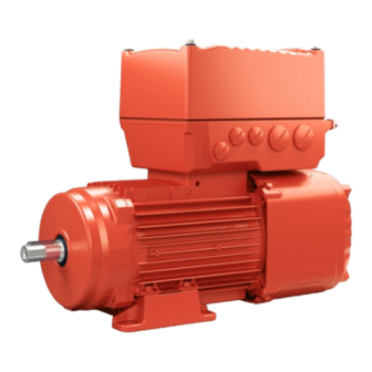
Device structure MOVIMOT® advanced drive unit Device structure MOVIMOT® advanced drive unit ® MOVIMOT advanced drive unit ® 7.1.1 MOVIMOT advanced DBC with electronics cover size 1 ® The MOVIMOT advanced drive unit consists of a decentralized inverter and a type DRN.. - Page 166 Device structure MOVIMOT® advanced drive unit ® 7.1.2 MOVIMOT advanced DBC with size 2 electronics cover with fan ® The MOVIMOT advanced drive unit consists of a decentralized inverter and a type DRN.. or DR2C.. motor (see following image). The decentralized inverter is referred to as the electronics cover in the following.
-
Page 167: Cable Entry Position
Device structure Cable entry position Cable entry position The device is equipped with the following cable bushings: • Position X, 2, 3 – X: 2 x M25 x 1.5 + 2 x M16 x 1.5 + 1 x M16 x 1.5 (only for option /PE) –... - Page 168 Device structure Cable entry position ® 7.2.1 Overview of MOVIMOT advanced DBC, DAC with electronics cover size 1 The following figure shows the possible cable entries: Connection box, not rotated: Rotated connec- tion box: ® Product Manual – MOVIMOT advanced...
- Page 169 Device structure Cable entry position ® 7.2.2 Overview of MOVIMOT advanced DBC, DAC with size 2 electronics cover with fan The following figure shows the possible cable entries: 34406751115 ® Product Manual – MOVIMOT advanced...
-
Page 170: Nameplate Positions
Device structure Nameplate positions Nameplate positions ® You can find the two nameplates for MOVIMOT advanced in positions X and 2. ® 7.3.1 Overview of MOVIMOT advanced DBC, DAC The following figure shows examples of the positions of the nameplates: 76646 Bruchsal/Germany WA20 DR2C71MSA4/TF 01.01234567890.0001.22... -
Page 171: Example Nameplate And Type Designation Of The Drive Unit
Device structure Example nameplate and type designation of the drive unit Example nameplate and type designation of the drive unit ® 7.4.1 MOVIMOT advanced nameplates ® The MOVIMOT advanced drive unit is always equipped with 2 nameplates: • Nameplate 1: Data of the drive unit. •... - Page 172 Device structure Example nameplate and type designation of the drive unit Nameplate 2 (..DR2C.. motor) The following image shows an example of a nameplate of the WA..DR2C.. gearmotor [1] [2] [3] [4] 76646 Bruchsal/Germany [15] WA20 DR2C71MSA4/TF 01.01234567890.0001.22 [14] 3~IEC60034 Inverter duty only VPWM 400 V Y...
- Page 173 Device structure Example nameplate and type designation of the drive unit Nameplate 2 (DRN.. motor) The following image shows an example of a nameplate of the DRN.. motor 76646 Bruchsal / Germany [17] DRN80M4/FF/DI/DFC/BW1 [16] 01.1774473607.0001.00 VPWM 3~IEC60034 Inverter duty [15] Hz 60 r/min 1751...
- Page 174 Device structure Example nameplate and type designation of the drive unit ® 7.4.2 Type designation of the MOVIMOT advanced DBC The following table shows the type designation of the drive unit. Gear unit series R = Primary gear unit Gear unit size DRN Product family DRN = Asynchronous motor of the DRN..
- Page 175 Device structure Example nameplate and type designation of the drive unit EI8Z Option EI8Z = Single-turn encoder with DDI connection AK8Z = Multi-turn absolute encoder with DDI connection IV = Plug connector TF = Motor protection D11 = Switch disconnector with feedback contact BW1 = Integrated BW 1 braking resistor BW2 = Integrated BW 2 braking resistor PE = Electronics pressure compensation fitting...
-
Page 176: Examples For The Optional Nameplate "Plug Connector Positions
Device structure Examples for the optional nameplate "Plug connector positions" Examples for the optional nameplate "Plug connector positions" The nameplate is not attached to the device. If the nameplate "Plug connector posi- tions" has been ordered, a nameplate is included in the delivery. 7.5.1 Design with electronics cover size 1 The following figure shows an example of the optional nameplate "Plug connector pos-... - Page 177 Device structure Examples for the optional nameplate "Plug connector positions" 7.5.2 Design with electronics cover size 2 with fan The following figure shows an example of the optional nameplate "Plug connector pos- itions": S0#: 01.1234567890.0001.21 X4142 X5504 X1203_2 X1203_1 X5505 34452869003 The nameplate shows the designations and positions of the plug connectors at the connection box.
-
Page 178: Electronics
Device structure Electronics Electronics 7.6.1 Overview of electronics cover Devices with the following electronics covers are available depending on the nominal output current: Electronics cover Nominal out- Type designation Size Image put current 2.0 A DBC...-0020.. Size 1 without cooling fins 2.5 A DBC...-0025.. - Page 179 Device structure Electronics 7.6.2 Connection box and electronics cover (internal) size 1 The following figure shows the connection box and the bottom side of the electronics cover: 3 5 6 [17] [18] [19] [17][21] [18] [1] [17] [18] [17] [16] [15] [14] [13] [12]...
- Page 180 Device structure Electronics 7.6.3 Connection box and electronics cover (internal) size 2 The following figure shows the connection box and the bottom side of the electronics cover: [18] [17] [17] [17] [16] [15] [14] [13] [12] [11] [10] 34445455371 Cable glands Line connection L1, L2, L3 (X1, only WITHOUT switch disconnector) Plug connector connection unit for electronics cover Braking resistor connection...
- Page 181 Device structure Electronics 7.6.4 Electronics cover (outer) size 1 The following figure gives an example of electronics cover designs: 29317784459 "LED displays" (→ 2 328) "Potentiometer f1 (underneath the screw plug)" (→ 2 288) "Potentiometer f2 (underneath the screw plug)" (→ 2 288) "Plug connector" (→ 2 277) 7.6.5 Electronics cover (outer) size 2 The following figure gives an example of electronics cover designs: 36725585163 "LED displays" (→ 2 328)
- Page 182 Device structure Electronics 7.6.6 Electronics cover (outer) size 2 with fan The following figure gives an example of electronics cover designs: 34237122187 "LED displays" (→ 2 328) "Potentiometer f1 (underneath the screw plug)" (→ 2 288) "Potentiometer f2 (underneath the screw plug)" (→ 2 288) "Plug connectors" (→ 2 277) ® Product Manual – MOVIMOT advanced...
-
Page 183: Example Nameplate And Type Designation Of Electronics
Device structure Example nameplate and type designation of electronics Example nameplate and type designation of electronics 7.7.1 Inner nameplate of DBC.. electronics cover The following figure gives an example of a nameplate of the electronics cover. For the structure of the type designation, refer to chapter "Type designation of the electronics cover". - Page 184 Device structure Example nameplate and type designation of electronics 7.7.3 Type designation of DBC.. electronics cover The following table shows the type designation of the electronics cover: DBC Product family DBC = Electronics cover Direct Binary Communication Type communication 1 = Binary Connection configuration 0 = M12 plug connector on electronics cover (standard) Communication version...
- Page 185 Device structure Example nameplate and type designation of electronics ® MOVIKIT version ® 000 = No MOVIKIT module loaded ex works Operating mode options B = Brake control C = Specific customer identification P = Customer-specific parameterization 7.7.4 Example: Nameplate of a replaceable memory module The following figure shows an example of the nameplate for the replaceable memory module: P#: 28242882...
-
Page 186: Example Nameplate And Type Designation Of Connection Unit
Device structure Example nameplate and type designation of connection unit Example nameplate and type designation of connection unit 7.8.1 Nameplate The following figure gives an example of a nameplate of the connection unit. For the structure of the type designation, refer to chapter "Type designation of the connection unit". -
Page 187: Markings
Device structure Markings Markings The following table shows an example of the markings on the nameplate. The CE mark states compliance with the following European directives: • Low Voltage Directive 2014/35/EU • EMC Directive 2014/30/EU • Machinery Directive 2006/42/EG • Directive 2011/65/EU for limiting the use of certain hazardous sub- stances in electrical and electronic equipment •... - Page 188 Device structure Markings Device with STO connection via terminals or plug connectors Device with secure communication to activate STO ® via the MOVISAFE CSB51A safety option ® Product Manual – MOVIMOT advanced...
-
Page 189: Mechanical Installation
Mechanical installation Installation notes Mechanical installation Installation notes Perform the following steps before installation: WARNING! Electric shock caused by dangerous voltages in the connection box. Severe or fatal injuries. De-energize the device. Pay attention to the 5 safety rules in chapter “Carrying out electrical work safely”. -
Page 190: Installation Requirements
Mechanical installation Installation requirements Installation requirements Check that the following conditions have been met: • The information on the drive unit's nameplate must match the voltage supply sys- tem. • The drive unit is undamaged (no damage caused by shipping or storage). •... -
Page 191: Setting Up The Drive Unit
Mechanical installation Setting up the drive unit Setting up the drive unit 8.6.1 Notes Pay attention to the following information when installing the drive unit: • Perform the steps described in chapter "Installation notes" (→ 2 189) before in- stalling the drive unit: •... - Page 192 Mechanical installation Setting up the drive unit 8.6.3 Electronics cover Installing the electronics cover Install the electronics cover as follows: WARNING! Risk of burns due to hot surfaces. Severe injuries. Let the device cool sufficiently before touching it. 2. NOTICE! Loss of the guaranteed degree of protection. Possible damage to prop- erty.
- Page 193 Mechanical installation Setting up the drive unit Removing the electronics cover Remove the electronics cover as follows: WARNING! Risk of burns due to hot surfaces. Severe injuries. Let the device cool sufficiently before touching it. 2. Undo the screws of the electronics cover. 3.
- Page 194 Mechanical installation Setting up the drive unit 8.6.7 Pressure compensation on electronics (option /PE) Fitting the provided pressure compensation fitting (option/PE) For designs with an included pressure compensation fitting (option /PE), install the fit- ting depending on the mounting position used. The tightening torque is 4.0 Nm. Pressure compensation fitting installation positions The following table shows the installation location-dependent mounting positions of the pressure compensation fitting (option/PE):...
-
Page 195: Tightening Torques
Mechanical installation Tightening torques Tightening torques ® 8.7.1 Examples of MOVIMOT advanced The following figure shows an example of the installation of the threaded blanking plugs, cable glands and electronics cover. The number and position of threaded blank- ing plugs and cable bushings depend on the ordered variant. 38411578379 Tighten the screws in diametrically opposite sequence with a tightening torque of 6.0 Nm (for size 1) or 9.5 Nm (for size 2). - Page 196 Mechanical installation Tightening torques 8.7.2 Tightening torques for cable glands Tighten cable glands optionally included delivery SEW‑EURODRIVE with the following torques: Screw fitting Part Contents Size Outer di- Tighten- number (pieces) ameter of cable torque (mm) (Nm) EMC cable glands 18204783 10 M16 ×...
-
Page 197: Electrical Installation
Electrical installation Installation planning taking EMC aspects into account Electrical installation Installation planning taking EMC aspects into account 9.1.1 Notes on arranging and routing installation components The correct operation of decentralized inverters depends on selecting the correct cables, providing correct grounding, and on a properly functioning equipotential bond- ing. - Page 198 Electrical installation Installation planning taking EMC aspects into account Example with electronics cover size 1 The following figure shows the connection of the equipotential bonding and the PE conductor: The mechanical installation of a drive unit with hollow shaft does not create a conductive connection of drive unit and mounting plate.
- Page 199 Electrical installation Installation planning taking EMC aspects into account Example with electronics cover size 2 The following figure shows the connection of the equipotential bonding and the PE conductor: The mechanical installation of a drive unit with hollow shaft does not create a conductive connection of drive unit and mounting plate.
-
Page 200: Equipotential Bonding At The Connection Box
Electrical installation Equipotential bonding at the connection box INFORMATION For detailed information on equipotential bonding for decentralized inverters and drive units, refer to the publication "Drive Engineering – Practical Implementation, EMC in Drive Engineering" in chapter "Equipotential Bonding of Decentralized Invert- ers"... - Page 201 Electrical installation Installation instructions Information on voltage supply sys- Information on permissibility tems IT systems – voltage systems with Use is only permitted with electronics cover in non-grounded star point IT system design (...-513-..). • For use in IT systems, SEW‑EURODRIVE recommends using insulation monitors with pulse-code measurement.
- Page 202 Electrical installation Installation instructions 4. Screw the screw [1] with the insulating bushing [2] into the electronics cover. Tighten the screw with a tightening torque of 1.4 to 1.6 Nm. 9007233821379851 5. Place the electronics cover onto the connection box and fasten the electronics cover.
- Page 203 Electrical installation Installation instructions 9.3.3 Permitted cable cross section of terminals Line terminals X1 Observe the permitted cable cross sections for installation: Line terminals X1 Without conductor end With conductor end sleeve sleeves (with or without plastic collar) Connection cross sec- 0.5 mm –...
- Page 204 Electrical installation Installation instructions 9.3.4 Activating line terminals X1 Adhere to the following sequence when actuating the line terminals X1: 25649924107 9.3.5 Actuating line terminals X1a Adhere to the following sequence when actuating the line terminals X1a: 34682210443 9.3.6 Activating terminals X3 for the braking resistor Adhere to the following sequence when actuating the X3 terminals for the braking re- sistor: 25650172171...
- Page 205 Electrical installation Installation instructions 9.3.7 Activating control terminals X9 Observe the following sequence when actuating the X9 control terminals: 30508870539 ® Product Manual – MOVIMOT advanced...
- Page 206 Electrical installation Installation instructions 9.3.8 Selecting the residual current device The inverter can cause a direct current in the protective earthing conductor. Proceed as follows when selecting the residual current device: 1. If using a residual current device is not mandatory according to the standards, SEW‑EURODRIVE recommends not using a residual current device.
- Page 207 Electrical installation Installation instructions 9.3.10 Notes on PE connection PE connection to devices with a lifting eye The handle is only used to transport the unit. The handle is not required for operation. 1. Remove the lifting eye. Store the lifting eye for future service work. WARNING! Electric shock due to faulty PE connection.
- Page 208 Electrical installation Installation instructions PE connection to devices with hoop guard The optional hoop guard is used to protect the connectors on the electronics cover. Do not remove the guard bracket. 1. Connect the PE cable to the guard bracket according to the following figure. 2.0 –...
- Page 209 Electrical installation Installation instructions Leakage currents Earth-leakage currents ≥ 3.5 mA can occur during normal operation. In order to fulfill EN 61800-5-1, observe the following notes: • The protective earth (PE) connection must meet the requirements for systems with high earth-leakage currents. • This usually means –...
- Page 210 Electrical installation Installation instructions 9.3.13 Installation above 1000 m amsl The devices can be used at altitudes above 1000 m above sea level up to 3800 m above sea level under the following marginal conditions. The maximum altitude is lim- ited due to the decreased dielectric strength at lower air density. •...
-
Page 211: Installation Topologies
Electrical installation Installation topologies Installation topologies 9.4.1 Installation topology (example: standard installation) ® The following figure shows the basic installation topology with MOVIMOT advanced: Safety relay Supply system Control Back-up fuse/line protection Control cabinet level Field level DBC.. ® MOVIMOT advanced DBC.. -
Page 212: Terminal Assignment Of Movimot Advanced Dbc
Electrical installation Terminal assignment of MOVIMOT® advanced DBC Terminal assignment of MOVIMOT® advanced ® Terminal assignment of MOVIMOT advanced DBC Attach units without a plug connector to the terminals as follows: WARNING! Electric shock caused by dangerous voltages in the connection box. - Page 213 Electrical installation Terminal assignment of MOVIMOT® advanced DBC 9.5.2 Connection box size 2 ® The following image shows the terminals of MOVIMOT advanced DBC, size 2: 11 12 13 14 15 16 21 22 23 24 25 26 11 12 13 34443087371 9.5.3 Assignment...
- Page 214 Electrical installation Terminal assignment of MOVIMOT® advanced DBC Terminal Marking Function – – Protective earth connection – Braking resistor connection braking re- – Braking resistor connection sistor termi- nals yellow F_STO_P1 Input STO+ control termi- yellow F_STO_P1 Input STO+ nals (to loop through) –...
- Page 215 Electrical installation Terminal assignment of MOVIMOT® advanced DBC The following figure shows the factory-installed jumpers at the X9 terminals: 11 12 13 14 15 16 21 22 23 24 25 26 29006177419 These jumpers are not present in the following designs: •...
-
Page 216: Connection Variants Functional Safety
Electrical installation Connection variants functional safety Connection variants functional safety 9.6.1 Connection via terminal X9 For detailed information on terminal X9, refer to chapter "Electrical Installation" > "Ter- minal assignment". Wiring diagrams Delivery state In delivery state, the terminals at the connection for safe disconnection X9 are jumpered. - Page 217 Electrical installation Connection variants functional safety 2-pole sourcing/sinking Example 1 F_STO_P1 F-DO_P F_STO_M F-DO_M F_STO_P2 F_STO_P1 0V24_OUT 24 V_OUT F_STO_M F_STO_P2 9007222818872587 [1] Drive unit [2] External safety device Example 2 F_STO_P1 F_STO_M F_STO_P2 F_STO_P1 0V24_OUT 24 V_OUT F_STO_M F_STO_P2 34106433163 [1] Drive unit [2] External safety device Observe the following notes: •...
- Page 218 Electrical installation Connection variants functional safety 2-pole serial sourcing 24 V F-DOR_11 F-DOR_12 F-DOR_21 F_STO_P1 F-DOR_22 F_STO_M F_STO_P2 F_STO_P1 0V24_OUT 24 V_OUT F_STO_M F_STO_P2 9007222818944907 [1] Drive unit [2] External safety device 1-pole sourcing F_STO_P1 F-DO_P F_STO_M F_STO_P2 F_STO_P1 0V24_OUT 24 V_OUT F_STO_M F_STO_P2...
- Page 219 Electrical installation Connection variants functional safety STO group disconnection, 2-pole, sourcing F_STO_P1 F-DO_P1 F_STO_M F_STO_P2 F-DO_P2 F_STO_P1 F_STO_M F_STO_P2 0V24_OUT 24 V_OUT F_STO_P1 F_STO_M F_STO_P2 F_STO_P1 F_STO_M F_STO_P2 0V24_OUT 24 V_OUT 25228151435 [1] Drive unit [2] External safety controller ® Product Manual –...
- Page 220 Electrical installation Connection variants functional safety STO group disconnection, 2-pole, sourcing/sinking F_STO_P1 F-DO_P F_STO_M F-DO_M F_STO_P2 F_STO_P1 F_STO_M F_STO_P2 0V24_OUT 24 V_OUT F_STO_P1 F_STO_M F_STO_P2 F_STO_P1 F_STO_M F_STO_P2 0V24_OUT 24 V_OUT 25228157067 [1] Drive unit [2] External safety controller ® Product Manual –...
- Page 221 Electrical installation Connection variants functional safety STO group disconnection, 2-pole, serial sourcing 24 V F-DOR_11 F-DOR_12 F-DOR_21 F_STO_P1 F-DOR_22 F_STO_M F_STO_P2 F_STO_P1 F_STO_M F_STO_P2 0V24_OUT 24 V_OUT F_STO_P1 F_STO_M F_STO_P2 F_STO_P1 F_STO_M F_STO_P2 0V24_OUT 24 V_OUT 25229441035 [1] Drive unit [2] External safety controller ®...
- Page 222 Electrical installation Connection variants functional safety STO group disconnection, 1-pole, sourcing F_STO_P1 F-DO_P F_STO_M F_STO_P2 F_STO_P1 F_STO_M F_STO_P2 0V24_OUT 24 V_OUT F_STO_P1 F_STO_M F_STO_P2 F_STO_P1 F_STO_M F_STO_P2 0V24_OUT 24 V_OUT 25229445003 [1] Drive unit [2] External safety controller ® Product Manual – MOVIMOT advanced...
- Page 223 Electrical installation Connection variants functional safety 9.6.2 Connection via M12 plug connector X5504/X5505 For further information on the connection of X5504/X5505, refer to chapter "Electrical installation" > "Assignment of optional plug connectors". Wiring diagrams Delivery state In the delivery state, plug connector X5504 is not connected, this means the STO in- put is active.
- Page 224 Electrical installation Connection variants functional safety Example 2 X5504 24V_OUT F_STO_P2 0V24_OUT F_STO_M F_STO_P1 34216188171 [1] Drive unit [2] External safety device Observe the following notes: • The supply voltages 0V24_OUT and 24V_OUT must not be used to supply the ex- ternal safety device.
- Page 225 Electrical installation Connection variants functional safety 1-pole sourcing X5504 F_STO_P2 F-DO_P F_STO_M F_STO_P1 23875545995 [1] Drive unit [2] External safety device ® Product Manual – MOVIMOT advanced...
- Page 226 Electrical installation Connection variants functional safety STO group disconnection, 2-pole, sourcing/sinking X5504 F_STO_P2 F-DO_P F_STO_M F-DO_M F_STO_P1 X5505 F_STO_P2 F_STO_M F_STO_P1 X5504 F_STO_P2 F_STO_M F_STO_P1 X5505 F_STO_P2 F_STO_M F_STO_P1 9007223142162187 [1] Drive unit [2] External safety device STO bridging plug (3-phase) WARNING Safe disconnection of the device is not possible when the jumper plug is used.
- Page 227 Electrical installation Connection variants functional safety WARNING Disabling of the safety-related disconnection of further devices due to parasitic voltages when using an STO jumper plug. Severe or fatal injuries. • Only use the STO jumper plug when all incoming and outgoing STO connections have been removed from the device.
-
Page 228: Movimot® Advanced Dbc Connection Diagram
Electrical installation MOVIMOT® advanced DBC connection diagram MOVIMOT® advanced connection diagram ® MOVIMOT advanced DBC connection diagram The following figure shows the connections of the device: F11/F12/F13 F11/F12/F13 ® MOVIMOT® advanced DBC Line terminals Engineering Line terminals Load disconnector interface Braking resistor Control terminals Analog input... -
Page 229: Cable Routing And Cable Shielding
Electrical installation Cable routing and cable shielding Cable routing and cable shielding 9.8.1 Accessory bag with installation equipment (part number 18241395) INFORMATION For some installation variants, you do not need all the parts of the accessory kit. The delivery of each drive unit includes the following accessory bag with installation materials for cable shielding (exception: Does not apply when all possible connections were ordered in plug connector design): •... - Page 230 Electrical installation Cable routing and cable shielding 9.8.2 General installation options The following chapters show common examples and contain important notes on cable selection and cable routing. Assembly of installation materials The following image illustrates the assembly of the installation material: Size 2 Size 1 ®...
- Page 231 Electrical installation Cable routing and cable shielding 9.8.3 Installation with separately routed binary signal cable Notes on cable routing and shielding – Recommended cable routing Note the following points for cable routing and cable shielding: • Cable selection – When selecting the cable, be mindful of the recommended connection cable in the product manual >...
-
Page 232: Emc Cable Glands
Electrical installation EMC cable glands EMC cable glands 9.9.1 Cable shielding (alternative) As an alternative to using shield clamps for shielded cables (e.g. control cables, STO cables, power cables), you can use EMC cable glands, which are available as an op- tion, to connect the shield. -
Page 233: Plug Connectors
Electrical installation Plug connectors 9.10 Plug connectors 9.10.1 Representation of connections The wiring diagrams of the plug connectors depict the contact end of the connections. 9.10.2 Connection cables INFORMATION For more information about cable types, see chapter "Technical data". Connection cables are not included in the scope of delivery. Prefabricated cables for connecting SEW‑EURODRIVE components are available to order. - Page 234 Electrical installation Plug connectors Cable routing Observe the permitted bending radii of the installed cables for cable routing. For de- tailed information, refer to chapter "Technical data" > "Dimension drawings of plug connectors of the connection box" > "Plug connectors including mating connect- ors" (→ 2 128).
- Page 235 Electrical installation Plug connectors ® 9.10.3 Plug connector positions of the MOVIMOT advanced DBC drive unit size 1 The following figure shows possible plug connector positions: X5134 X1523 X4142 X5505 X5504 X4142 X1523 X5134 X5504 X5505 X2242 X1206 X5136 X1203_2 X1203_1 X1207 X2328...
- Page 236 Electrical installation Plug connectors Plug connectors Not together at a position with the Designation Coding ring/ Function Position plug connector: color • X1206 X1203_1 Black "AC 400 V connection" (→ 2 247) X, 2 or 3 • X1207 • X1217 X1203_2 Black "AC 400 V connection" (→ 2 247) X, 2 or 3 •...
- Page 237 Electrical installation Plug connectors Plug connectors Not together at a position with the Designation Coding ring/ Function Position plug connector: color • Optional pres- [2] Optional connection for equipo- X or 2 sure compensa- tential bonding tion 1) Plug connector X1203_1 can also be ordered separately (i.e. without plug connector X1203_2). 2) Plug connector X1206 can also be ordered separately (i.e.
- Page 238 Electrical installation Plug connectors ® 9.10.4 Plug connector positions of the MOVIMOT advanced DBC drive unit size 2 Cable entry M25 The following figure shows possible plug connector positions: X1206 X1203_2 X1203_1 X1217 X1207 X5136 X1206 X1203_1 X1203_2 X1207 X1217 X5136 X1203_2 X1203_1...
- Page 239 Electrical installation Plug connectors Plug connectors Not together at a position with the Designation Coding ring/ Function Position plug connector: color • X1206 X1203_1 Black "AC 400 V connection" (→ 2 247) X, 2 or 3 • X1207 • X1217 X1203_2 Black "AC 400 V connection" (→ 2 247) X, 2 or 3 •...
- Page 240 Electrical installation Plug connectors Cable entry M16 The following figure shows possible plug connector positions: X1523 X4142 X5505 X5504 X5504 X5505 X4142 X1523 X5504 X5505 X4142 9007233714050827 Plug connectors Not together at a position with the Designation Coding ring/ Function Position plug connector: color...
- Page 241 Electrical installation Plug connectors Plug connectors Not together at a position with the Designation Coding ring/ Function Position plug connector: color • Optional pres- [2] Optional connection for equipo- X or 2 sure compensa- tential bonding tion 1) Plug connectors X5504 and X5505 can only be ordered together. 9.10.5 Plug connector positions at the DBC..
- Page 242 Electrical installation Plug connectors 9.10.6 Plug connector variants M12 plug connector at the connection box M12 plug connectors at the connection box are pre-installed at delivery so they match the connection cables provided by SEW‑EURODRIVE. Customers can adjust the alignment of plug connectors if required. The following figure shows a schematic illustration with the permitted tightening torque: 6 Nm...
- Page 243 Electrical installation Plug connectors M12 plug connector with mating connector at connection box or electronics cover The following figure shows a schematic illustration with the permitted tightening torques: 0.4 – 0.6 Nm 32845364363 INFORMATION The M12 plug connectors are usually tightened with a torque of 0.4 – 0.6 Nm. Ob- serve the data sheet of the used prefabricated cables.
- Page 244 Electrical installation Plug connectors M23 plug connector The M23 plug connectors are available in the following variants: • [1] "Straight" plug connector • [2] "Angled" plug connector After plugging in the mating connector, you can align the angled connector without the need for additional tools.
- Page 245 Electrical installation Plug connectors 9.10.7 Using plug connectors assembled by yourself M23 plug connector by TE connectivity – Intercontec Products The power plug connectors for assembling connection cables yourself, and the corre- sponding assembly tool set is available for order from TE Connectivity - Intercontec products.
- Page 246 Electrical installation Plug connectors Mini-I/O plug connector The following tables contains the part numbers and purchase order numbers of the mini-I/O plug connectors for customer assembly of mini I/O connection cables. Connector type Cable Cable Purchase order num- Part number Outer diameter Category SEW‑EURODRIVE...
-
Page 247: Optional Plug Connector Assignment
The following table provides information about this connection: Function AC 400 V connection for supplying the device/for looping through Connection type M23, SEW-EURODRIVE insert, Series 723, SpeedTec equipment, company: TE Connectivity – Intercontec products, female, coding ring: black, protected against contact Pin assignment... - Page 248 Electrical installation Optional plug connector assignment Connection cables Cable cross section 1.5 mm The following table shows the cables available for this connection: Connection cable Conformity/ Cable type Length/in- Cable part num- stallation cross sec- type tion/operat- ing voltage ® HELUKABEL Variable 1.5 mm...
- Page 249 Electrical installation Optional plug connector assignment Connection cable Conformity/ Cable type Length/in- Cable part num- stallation cross sec- type tion/operat- ing voltage ® HELUKABEL Variable 2.5 mm ® MULTIFLEX 18153275 – 512 AC 500 V M23, coding M23, coding ring: black, ring: black, male male ®...
- Page 250 Electrical installation Optional plug connector assignment Cable cross section 4.0 mm The following table shows the cables available for this connection: Connection cable Conformity/ Cable type Length/in- Cable part num- stallation cross sec- type tion/operat- ing voltage ® HELUKABEL Variable 4.0 mm ®...
- Page 251 Electrical installation Optional plug connector assignment Connection cable Conformity/ Cable type Length/in- Cable part num- stallation cross sec- type tion/operat- ing voltage ® HELUKABEL Variable 4.0 mm ® TOPFLEX – 18133983 611-PUR AC 500 V (halogen-free) Open M23, coding ring: black, male ® HELUKABEL Variable 4.0 mm...
- Page 252 Electrical installation Optional plug connector assignment Connection of cables with open end The following table shows the core assignment of cables with the following part num- bers: Part numbers 18180094, 18127479, 18133967, 18153283, 18153291, 18127495, 18133983, 18153321, 18153348 Assembly Open cable end Description Prefabricated plug connector...
- Page 253 Electrical installation Optional plug connector assignment 9.11.2 X1206: AC 400 V connection (IN) The following table provides information about this connection: Function AC 400 V connection (IN) Connection type MQ15-X-Power, male, plug connector without union nut, MURR Elektronik, (current load max. 16 A) Pin assignment Assignment Contact...
- Page 254 Electrical installation Optional plug connector assignment 9.11.3 X2242: AC 400 V connection (OUT) The following table provides information about this connection: Function AC 400 V connection (OUT) Connection type MQ15-X-Power, female, plug connector with union nut, MURR Elektronik, (current load max. 16 A) Pin assignment Assignment Contact...
- Page 255 Electrical installation Optional plug connector assignment 9.11.4 X1207: AC 400 V connection (IN) INFORMATION The number of permitted plug-in cycles for this connector is 10 times. The following table provides information about this connection: Function AC 400 V connection (IN) Connection type QPD W 4PE2,5, QUICKON connector, coding 3, male, PhoenixContact Pin assignment Assignment...
- Page 256 Electrical installation Optional plug connector assignment 9.11.5 X1217: PA connection for AC 400 V and 24 V backup voltage (IN) The following table provides information about this connection: Function PA connection for AC 400 V and DC 24 V backup voltage (IN) Connection type MQ15-X-Power, male, plug connector without union nut, MURR Elektronik, (current load max.
- Page 257 Electrical installation Optional plug connector assignment 9.11.6 X2328: PA connection for AC 400 V and 24 V backup voltage (OUT) The following table provides information about this connection: Function PA connection for AC 400 V and DC 24 V backup voltage (OUT) Connection type MQ15-X-Power, female, plug connector with union nut, MURR Elektronik, (current load max.
- Page 258 Electrical installation Optional plug connector assignment 9.11.7 X5504: STO (3 cores) WARNING No safe disconnection of the device. Severe or fatal injuries. • You may bridge the STO connection with 24 V only if the device is not intended to fulfill any safety functions. The following table provides information about this connection: Function Connection for safe torque off (STO, 3 conductors)
- Page 259 Electrical installation Optional plug connector assignment Connection cables INFORMATION Use only shielded cables for this connection and only suitable plug connectors that connect the shield with the device in an HF-capable manner. The following table shows the cables available for this connection: Connection cable Conformity/ Cable type...
- Page 260 Electrical installation Optional plug connector assignment Connection cable Conformity/ Cable type Length/in- Cable part num- stallation cross sec- type tion/operat- ing voltage CE/UL: igus chainflex Variable 4 x 0.5 mm CF78.UL 28110994 DC 60 V M12, 5‑pin, M12, 5‑pin, A‑coded, fe- A‑coded, male male CE/UL: igus chainflex...
- Page 261 Electrical installation Optional plug connector assignment Connection of cables with open end ® HELUKABEL The following table shows the core assignment of cables with the following part num- bers: Part numbers 28110978, 28110943 Assembly Open cable end Description Prefabricated plug connector Conductor Identi-...
- Page 262 Electrical installation Optional plug connector assignment igus chainflex The following table shows the core assignment of cables with the following part num- bers: Part numbers 28111001, 28111036 Assembly Open cable end Description Prefabricated plug connector Conductor Identi- Assembly Signal Contact color/ fication core cross...
- Page 263 Electrical installation Optional plug connector assignment 9.11.8 X5505: STO (3 cores) WARNING Disabling of the safety-related disconnection of further devices due to parasitic voltages when using an STO jumper plug. Severe or fatal injuries. • Only use the STO jumper plug when all incoming and outgoing STO connections have been removed from the device.
- Page 264 Electrical installation Optional plug connector assignment Connection cables INFORMATION Use only shielded cables for this connection and only suitable plug connectors that connect the shield with the device in an HF-capable manner. The following table shows the cables available for this connection: Connection cable Conformity/ Cable type...
- Page 265 Electrical installation Optional plug connector assignment Connection cable Conformity/ Cable type Length/in- Cable part num- stallation cross sec- type tion/operat- ing voltage CE/UL: igus chainflex Variable 4 x 0.5 mm CF78.UL 28110994 DC 60 V M12, 5‑pin, M12, 5‑pin, A‑coded, fe- A‑coded, male male CE/UL: igus chainflex...
- Page 266 Electrical installation Optional plug connector assignment Connection of cables with open end ® HELUKABEL The following table shows the core assignment of cables with the following part num- bers: Part numbers 28117808, 28110986 Assembly Open cable end Description Prefabricated plug connector Conductor Identi-...
- Page 267 Electrical installation Optional plug connector assignment igus chainflex The following table shows the core assignment of cables with the following part num- bers: Part numbers 28117816, 28111044 Assembly Open cable end Description Prefabricated plug connector Conductor Identi- Assembly Signal Contact color/core fication cross sec-...
- Page 268 Electrical installation Optional plug connector assignment 9.11.9 X5134: Digital inputs, relay output The following table provides information about this connection: Function Digital inputs/outputs Connection type M12, 8-pin, male, A-coded Pin assignment Assignment Contact Function Signal relay DI04/RESET Binary input DI04 DI01/R Binary input DI01 DI02/L...
- Page 269 Electrical installation Optional plug connector assignment 9.11.10 X5136: Digital inputs, relay output The following table provides information about this connection: Function Digital inputs, relay output Connection type M23, female, male thread, TE Connectivity-Intercontec products, P insert, SpeedTec equipment, 12‑pin, 0°-coded, coding ring: without, protected against contact Pin assignment Assignment Contact...
- Page 270 Electrical installation Optional plug connector assignment Connection cable INFORMATION Use only shielded cables for this connection and only suitable plug connectors that connect the shield with the device in an HF-capable manner. The following table shows the cables available for this connection: Connection cable Conformity/ Cable type...
- Page 271 Electrical installation Optional plug connector assignment Connection of cables with open end The following table shows the core assignment of cables with the following part num- bers: Part numbers 11741457 Assembly Open cable end Description Prefabricated plug connector Core Identi- Assembly Signal Contact...
- Page 272 Electrical installation Optional plug connector assignment 9.11.11 X1523: DC 24 V backup voltage, input The following table provides information about this connection: Function Input DC 24 V backup voltage Connection type M12, 5‑pin, male, L‑coded, color: light gray Pin assignment Assignment Contact Function +24V/L1 DC 24 V input/L1 (for backup mode) 0 V 24/N2...
- Page 273 Electrical installation Optional plug connector assignment Connection cables The following table shows the cables available for this connection: Connection cable Conformity/ Cable type Length/in- Cable part num- stallation cross sec- type tion/operat- ing voltage ® HELUKABEL Variable 5 x 2.5 mm JZ-500 28114345 DC 60 V...
- Page 274 Electrical installation Optional plug connector assignment Connection cable Conformity/ Cable type Length/in- Cable part num- stallation cross sec- type tion/operat- ing voltage ® CE/UL: HELUKABEL Variable 5 x 2.5 mm Li9Y11Y-HF 28117794 DC 60 V M12, 5‑pin, Open L‑coded, fe- male Connection of cables with open end The following table shows the core assignment of cables with the following part num- bers: Part numbers...
- Page 275 DC 24 V auxiliary output 0V24_OUT 0 V 24 reference potential CAN_H CAN High connection CAN_L CAN Low connection 1) Only use this output to supply components by SEW‑EURODRIVE. 2) You may use this output only to supply SEW-EURODRIVE components. ® Product Manual – MOVIMOT advanced...
- Page 276 Electrical installation Optional plug connector assignment Connection cables The following table shows the cables available for this connection: Connection cable Conformity/ Length/in- Operating part num- stallation voltage type Connection to interface adapter USM21A: 3.0 m DC 60 V USK15A 28139038 M12-SPEED- RJ10 CON, 5-pin, B‑coded, male Connection to CBG..
-
Page 277: Plug Connector Assignment At The Electronics Cover
Electrical installation Plug connector assignment at the electronics cover 9.12 Plug connector assignment at the electronics cover 9.12.1 X5231: Analog input The following table provides information about this connection: Function Analog input Connection type M12, 5‑pin, female, A-coded, color: black Pin assignment Assignment Contact... -
Page 278: Pc Connection
Electrical installation PC connection 9.13 PC connection ® Connect the PC to the drive unit before starting the MOVISUITE engineering soft- ware. You have several options to connect a PC to the drive unit. Follow the information in the product manual > chapter "Electrical Installation" > "PC Connection". - Page 279 Electrical installation PC connection Connection to X4142 (M12 at the connection box) The engineering interface X31 at the connection unit in the connection box is assigned to the internal wiring of plug connector X4142. X4142 32385960459 USB 2.0 connection cable (commercially available, included in the scope of delivery of USM21A) USM21A interface adapter Connection cable RJ10/M12 (USK15A)
- Page 280 Electrical installation PC connection Installing the included engineering plug connector X4142 SEW‑EURODRIVE supplies the engineering plug connector X4142 in some cases in an accessory bag (part number: 28273273) with the drive unit. In this case, install the engineering plug connector X4142 to the connection box of the drive unit as follows: 1.
- Page 281 Electrical installation PC connection Connection to X31 (RJ10 in the connection box) NOTICE Connector X31 provides a 24 V supply voltage for operating the connected options. Damage to connected options with low nominal voltage. • Only connect options with a nominal voltage of 24 V to connector X31, such as: –...
- Page 282 Electrical installation PC connection 9.13.2 Connection via keypad You can establish a connection between the PC and the device's engineering inter- face using the CBG22A, CBG21A, CBG11A or CBM22A keypads. The data is transferred according to the USB 2.0 standard. It is also possible to work with a USB 3.0 interface.
- Page 283 Electrical installation PC connection Connection to X31 (RJ10 in the connection box) NOTICE Connector X31 provides a 24 V supply voltage for operating the connected options. Damage to connected options with low nominal voltage. • Only connect options with a nominal voltage of 24 V to connector X31, such as: –...
-
Page 284: Startup
Startup Startup notes Startup 10.1 Startup notes Perform the following steps before startup: WARNING! Electric shock caused by dangerous voltages in the connection box. Severe or fatal injuries. De-energize the device. Pay attention to the 5 safety rules in chapter “Carrying out electrical work safely”. -
Page 285: Startup Requirements
Startup Startup requirements ® ð Lock the function using the parameter Release brake/deactivate DynaStop with FCB01 – Enable = "0" (Path: Funktionen > Antriebsfunktionen > FCB01 Endstufensperre). [Functions > Drive functions > FCB01 Output stage inhibit] ® 3. In the MOVISUITE engineering software, configure the parameters according to the lifting application requirements and its safety assessment. -
Page 286: Parameterization Mode
Startup Parameterization mode 10.3 Parameterization mode The following parameterization modes are available to perform the device startup: Easy mode Easy startup with predefined control interface. • Setting parameters, setpoints, and additional functions can only be set using the mechanical setting elements (potentiometer and DIP switch) at the device. •... -
Page 287: Control Elements
Startup Control elements 10.4 Control elements 10.4.1 Overview of control elements The following figure gives an overview of the control elements at the electronics cover. Size 1 S1 1 2 3 4 1 2 3 4 S2 S1 1 2 3 4 3 4 1 2 3 1 2 3 4 S2 4 S2... - Page 288 Startup Control elements 10.4.2 Potentiometer f1 NOTICE Loss of the ensured degree of protection if the screw plug of the potentiometer is not installed or not installed correctly. Damage to the device. • After setting the setpoint, make sure the screw plug of the potentiometer has a seal and screw it in.
- Page 289 Startup Control elements The following figure shows how to scale the speed setpoint f2 using potentiometer f2: Speed setpoint f2 Application limit positive 9 10 Potentiometer position 18014427791524235 Depending on the selected direction of rotation, the parameter Application limit positive or the parameter Application limit negative are used to scale the speed setpoint f2.
-
Page 290: Dip Switches
Startup DIP switches 10.5 DIP switches 10.5.1 Overview NOTICE Damage to the DIP switches caused by unsuitable tools. Damage to property. • Set the DIP switches only using suitable tools, such as a slotted screwdriver with a blade width of ≤ 3 mm. •... - Page 291 Startup DIP switches DIP switch S1 The following table shows the functions of DIP switch S1: DIP switch Meaning Direction of Release brake/ Speed moni- Reserved rotation re- deactivate toring deactiv- ® versal DynaStop ation with FCB01 – enable Speed monitor- Speed moni- toring 1) The factory settings are shown in boldface.
- Page 292 Startup DIP switches 10.5.2 Description of the DIP switches DIP switch S1/1: Reversing the direction of rotation INFORMATION The direction of rotation is reversed depending on the setting of the DIP switch and of the parameter drive train 1 > Controller > Direction of rotation reversal. If both set- tings are active, the speed setpoint is not inverted (logical XOR).
- Page 293 Startup DIP switches DIP switch S1/3: Deactivating the speed monitoring INFORMATION If the function of this DIP switch is deactivated via parameter access, the last active setting of the relevant parameter is maintained. This DIP switch is used to disable speed monitoring. •...
-
Page 294: Startup Procedure
Startup Startup procedure 10.6 Startup procedure 10.6.1 Startup in Easy mode In Easy mode (delivery state), startup is performed without a PC or keypad. The device functions are predefined in Easy mode. The setpoint is only set using mechanical setting elements (potentiometer, DIP switch). - Page 295 Startup Startup procedure Advanced • FCB 01 Output stage inhibit drive functions • FCB 02 Stop default • FCB 26 Stop at user limit • Limit values 1 Monitoring functions • Control functions 1 • Energy-saving function Information on the Device data is available via the project node. drive unit Device data •...
-
Page 296: Startup With Cbg22A On-Site Keypad
Startup Startup with CBG22A on-site keypad 10.7 Startup with CBG22A on-site keypad You can intuitively perform startup using the CBG22A on-site keypad using the sym- bols and the functions on the color display. You can find more information in the product manual > chapter "Startup" > "Startup with CBG22A on-site keypad". - Page 297 Startup Startup with CBG22A on-site keypad Symbols used The selectable functions are illustrated via the on-site keyboard using pictograms. Start menu Monitoring ® MOVISAFE CS.. DIP switch Process data Digital inputs/outputs Operating and energy data Device information Fault memory Gateway operation Settings Main menu ®...
- Page 298 Startup Startup with CBG22A on-site keypad Direct control mode active Indirect control mode active Manual mode ® Product Manual – MOVIMOT advanced...
-
Page 299: Startup With The Cbg21A Keypad
Startup Startup with the CBG21A keypad 10.8 Startup with the CBG21A keypad Using the CBG21A keypad, startup can be performed intuitively guided by the sym- bols and functions of the color display. INFORMATION You cannot take a drive train into operation using a keypad with this drive unit. You ®... - Page 300 Startup Startup with the CBG21A keypad Symbols used The available functions are shown with pictograms in the keypad display. Manual operation Optimization of the control mode Application Diagnostics Parameter Data management Settings Back Next ® Product Manual – MOVIMOT advanced...
-
Page 301: Startup With The Cbg11A Keypad
Startup Startup with the CBG11A keypad 10.9 Startup with the CBG11A keypad Using the CBG11A keypad, startup can be performed intuitively guided by the sym- bols and functions of the color display. See product manual INFORMATION You cannot start up a motor with encoder using the keypad. ®... -
Page 302: 10.10 Configuring The Digital Inputs/Outputs
Startup Configuring the digital inputs/outputs Symbols used The available functions are shown with pictograms in the keypad display. Diagnostics Data management Startup Manual operation Parameter tree Keypad settings A firmware update of the drive unit is not possible with the CBG11A keypad. 10.10 Configuring the digital inputs/outputs Easy mode (deliv- In Easy mode, the following configuration of the digital inputs is active:... -
Page 303: 10.11 Setpoint Scaling Of The Analog Input
Startup Setpoint scaling of the analog input 10.11 Setpoint scaling of the analog input The setpoint scaling of analog input AI1 depends on the operating mode of the fixed setpoint processing. Operating mode Setpoint scaling on the operating mode: "Mechanical setting elements": "Mechanical The following figure shows the setpoint scaling of the analog input AI1: setting elements"... -
Page 304: Configuring The Drive Behavior At Standstill (Fcb 02, Fcb 13, Fcb 14)
Startup Configuring the drive behavior at standstill (FCB 02, FCB 13, FCB 14) 10.12 Configuring the drive behavior at standstill (FCB 02, FCB 13, FCB 14) The parameter Behavior at standstill defines the drive behavior in case the drive en- able is revoked and the motor is at standstill (path: Functions >... -
Page 305: Operation
Operation Switch disconnector Operation 11.1 Switch disconnector NOTICE Increased wear of the switch contacts. Destruction of the switch contacts. • Do not operate the switch disconnector under load. The switch disconnector of the device serves to interrupt the voltage supply of the electronics cover. - Page 306 Operation Binary controller No. Configuration of the digital inputs Description CW, CCW, setpoint changeover • Direction of rotation positive, nega- tive • 2 Speed setpoints • Fault reset Fixed setpoint processing mode: • Mechanical setting elements Enable, fixed setpoints • Enable •...
- Page 307 Operation Binary controller 11.2.1 Configuration 0: User-defined configuration Function of the • The digital inputs can be configured freely. digital inputs • In contrast to the predefined terminal configurations 1 – 6, the drive unit remains in the status "FCB 02 Stop default" once the enable signal is revoked. If you require the status "FCB 01 Output stage inhibit", you must assign this function to a digital input.
- Page 308 Operation Binary controller 11.2.2 Configuration 1: CW, CCW, setpoint changeover Fixed setpoint processing mode: Mechanical setting elements (cannot be changed) Configuration 1 is active in Easy mode and in the delivery state. Behavior of the drive unit Digital input "DRIVE" DI01 DI02 DI03...
- Page 309 Operation Binary controller 11.2.3 Configuration 2: Enable, fixed setpoints Fixed setpoint processing mode: Mechanical setting elements (cannot be changed) Behavior of the drive unit Digital input "DRIVE" DI01 DI02 DI03 DI04 Enable Fixed Fixed Reset setpoint setpoint The drive unit stops with deceleration setpoint t1. Illuminates yellow FCB 01 Output stage inhibit is activated afterwards.
- Page 310 Operation Binary controller 11.2.4 Configuration 3: Enable, external fault, setpoint changeover Fixed setpoint processing mode: Mechanical setting elements (cannot be changed) Behavior of the drive unit Digital input "DRIVE" DI01 DI02 DI03 DI04 Enable Exter- Potenti- Reset ometer fault The drive unit stops with deceleration setpoint t1. Illuminates yellow FCB 01 Output stage inhibit is activated afterwards.
- Page 311 Operation Binary controller 11.2.5 Configuration 4: Motor potentiometer right Fixed setpoint processing mode: Motor potentiometer (cannot be changed) Behavior of the drive unit Digital input "DRIVE" DI01 DI02 DI03 DI04 Right Motor Motor Reset potenti- potenti- ometer ometer down The drive unit stops with deceleration setpoint t1. Illuminates yellow FCB 01 Output stage inhibit is activated afterwards.
- Page 312 Operation Binary controller 11.2.6 Configuration 5: Motor potentiometer left Fixed setpoint processing mode: Motor potentiometer (cannot be changed) Behavior of the drive unit Digital input "DRIVE" DI01 DI02 DI03 DI04 Left Motor Motor Reset potenti- potenti- ometer ometer down The drive unit stops with deceleration setpoint t1. Illuminates yellow FCB 01 Output stage inhibit is activated afterwards.
- Page 313 Operation Binary controller 11.2.7 Configuration 6: CW, CCW, primary frequency Fixed setpoint processing mode: Primary frequency setpoint (cannot be changed) Behavior of the drive unit Digital input "DRIVE" DI01 DI02 DI03 DI04 Right Left Input Reset fre- quency The drive unit stops with deceleration setpoint t1. Illuminates yellow FCB 01 Output stage inhibit is activated afterwards.
-
Page 314: Manual Mode With Movisuite
Operation Manual mode with MOVISUITE® Manual mode with MOVISUITE ® ® 11.3 Manual mode with MOVISUITE For manual operation of the device, you can use the manual mode function of the ® MOVISUITE engineering software. 1. First connect the PC to the device, see chapter "PC connection". ®... - Page 315 Operation Manual mode with MOVISUITE® Deactivation WARNING Risk of injury if the device starts up unintentionally. Severe or fatal injuries. • Before deactivating manual mode, take measures to prevent the device from starting up unintentionally. • Take additional safety precautions depending on the application to avoid injury to people and damage to machinery.
-
Page 316: Drive Unit Behavior In Case Of A Voltage Failure
Operation Drive unit behavior in case of a voltage failure Advanced functions and displays of manual mode ® The following functions are available in manual mode using MOVISUITE Release brake Dis- Actual values Digital inputs and Acceleration Ref- able output stages outputs erence travel Timeout... -
Page 317: Function "Release Brake/Deactivate Dynastop
Operation Function "Releasing the brake / deactivating DynaStop® with FCB 01" Function "Releasing the brake / deactivatin g D ynaStop® with FCB 01" ® 11.5 Function "Release brake/deactivate DynaStop with FCB01" 11.5.1 Activating the function WARNING Danger due to falling loads. Severe or fatal injuries. - Page 318 Operation Function "Releasing the brake / deactivating DynaStop® with FCB 01" 18014420484359179 2. Configuring the control signal: ð Control digital input ® Assign a digital input with the function "Release brake/deactivate DynaStop with FCB01" [2]. 18014420484362123 ð Control process data (not available designs)
-
Page 319: Mechanical Brake In Conjunction With Sto
Operation Mechanical brake in conjunction with STO 11.6 Mechanical brake in conjunction with STO 11.6.1 Using the mechanical brake in conjunction with the STO function The following table shows the behavior of the drive depending on the parameter set- tings: Index Parameter Setting... -
Page 320: Safety
Operation IT safety 11.7 IT safety 11.7.1 Hardening measures Perform the following hardening measures: • Regularly check if updates are available for your products. • Report incidents concerning IT security by e-mail to cert@sew‑eurodrive.com. • Regularly check which Security Advisories are available in the Online Support of SEW‑EURODRIVE. -
Page 321: Service
Service Failures of the mechanical drive Service NOTICE Improper work on the drive units can result in damage. Damage to property. • Make sure that the drives from SEW‑EURODRIVE are repaired by qualified per- sonnel only. • Consult SEW‑EURODRIVE SERVICE. 12.1 Failures of the mechanical drive Follow the information in the "DR..71-315, DRN63-315, DR2..56-80 AC motors"... - Page 322 Service Failures of the mechanical drive 12.1.2 Brake malfunctions The following table shows fault diagnostics options for malfunctions of the brake: Fault Possible cause Measure • Contact SEW‑EURODRIVE Brake does not re- Electronics cover defec- Service lease tive • Replace electronics cover Max.
-
Page 323: Evaluating Fault Messages
Service Evaluating fault messages 12.2 Evaluating fault messages ® 12.2.1 MOVISUITE ® The following section shows a sample evaluation of a fault message in MOVISUITE ® 1. Open the parameter tree in MOVISUITE 2. In the parameter tree [6], select the "Status" node. ð... -
Page 324: Switch-Off Responses
Service Switch-off responses 12.3 Switch-off responses The following table describes the shut-off responses to faults: Fault response Description No response The inverter ignores the event. Warning with self-reset The inverter issues a warning message with self-reset. Warning The inverter issues a warning message. Application stop (with output The inverter stops with the deceleration set for the application limit. -
Page 325: Fault Messages With Parameterizable Response
Service Fault messages with parameterizable response 12.4 Fault messages with parameterizable response The following table shows the fault messages with parameterizable responses: Fault Description Index Possible fault response • No response Heat sink overtempera- Here you can set the device re- 8622.2 ture –... - Page 326 Service Fault messages with parameterizable response Fault Description Index Possible fault response • No response External synchronization Here you can set the device re- 8622.7 sponse to loss of external synchro- • Warning nization. • Application stop (with out- put stage inhibit) •...
- Page 327 Service Fault messages with parameterizable response Fault Description Index Possible fault response • Warning Encoder – warning Here you can set the device re- 8622.13 sponse to an encoder warning. • Application stop (with out- put stage inhibit) • Emergency stop (with out- put stage inhibit) •...
-
Page 328: Resetting Fault Messages
Service Resetting fault messages 12.5 Resetting fault messages WARNING Eliminating the cause of the problem or performing a reset may result in the drive re- starting automatically. Severe or fatal injuries. • Prevent unintended startup. Acknowledge fault message by: • Switch the supply system off and on again. - Page 329 Service Description of status and operating displays 12.6.2 General LEDs "DRIVE" status LED The following table describes the display functions of the "DRIVE" LED: Operating status/ Meaning Measure Fault Subfault code code – Not ready for operation Line voltage absent. Power on the line voltage.
- Page 330 Service Description of status and operating displays Operating status/ Meaning Measure Fault Subfault code code Green/red Ready for operation A displaying fault is present. Please consult product manual > Flashes with The output stage is enabled. "Fault table" chapter changing colors, The motor is in operation.
- Page 331 Service Description of status and operating displays Operating status/ Meaning Measure Fault Subfault code code 1, 2 Output stage monitoring fault Contact SEW‑EURODRIVE Continuous illu- Brake chopper fault Service. mination DC link fault 3, 4, 8 Control mode fault 2, 99 Data Flexibility fault 7, 8 Temperature monitoring fault...
-
Page 332: Fault Table
Service Fault table 12.7 Fault table 12.7.1 Fault 1 Output stage monitoring Subfault: 1.1 Description: Overcurrent on motor output terminals Response: Output stage inhibit Cause Measure Power output stage defective. Contact SEW‑EURODRIVE Service. Motor current too high. Connect a smaller motor. Short circuit at the motor output. - Page 333 Service Fault table 12.7.2 Error 3 ground fault Subfault: 3.1 Description: Ground fault Response: Output stage inhibit Cause Measure Ground fault detected in the storage line. Eliminate the ground fault. Ground fault in the storage unit. Contact the service department of the respective storage unit manufacturer.
- Page 334 Service Fault table 12.7.5 Fault 7 DC link Subfault: 7.1 Description: Overvoltage in the DC link Response: Output stage inhibit Cause Measure Maximum permitted DC link voltage exceeded. – Check the connection of the braking resistor. – Decrease deceleration. – Check the configuration of the braking resistor (resistance value).
- Page 335 Service Fault table Subfault: 8.3 Description: Maximum speed at motor shaft exceeded Response: Output stage inhibit Cause Measure The setpoint is too high. Reduce the setpoint. The motor is driven by the load. Check the project planning of the drive. The actual speed has exceeded the "Maximum Reduce the maximum speed.
- Page 336 – Check the motor windings. pressed into the motor. – If the fault occurs repeatedly, contact SEW‑EURODRIVE Service. INFORMATION to SEW-EURODRIVE Service: Check the output stage. Subfault: 9.5 Description: Maximum output frequency exceeded Response: Output stage inhibit...
- Page 337 Service Fault table Subfault: 9.10 Description: Rotor stall monitoring Response: Output stage inhibit Cause Measure The current control cannot hold the load torque. Reduce the load. Subfault: 9.11 Description: Standstill current function not possible Response: Output stage inhibit Cause Measure In ELSM®...
- Page 338 Service Fault table 12.7.8 Fault 10 Data Flexibility Subfault: 10.1 Description: Initialization error Response: Application stop + output stage inhibit Cause Measure Error detected in Init task. The return code is not Check the program. Contact SEW‑EURODRIVE Service. Subfault: 10.2 Description: Illegal program command Response: Application stop + output stage inhibit Cause...
- Page 339 Service Fault table Subfault: 10.6 Description: Runtime error Response: Application stop + output stage inhibit Cause Measure The watchdog has detected an error. The pro- Check the program. Contact SEW‑EURODRIVE gram execution time exceeds the permitted time. Service. Execution time of PDI task or PDO task exceeds –...
- Page 340 Service Fault table Subfault: 10.11 Description: No application program loaded Response: Output stage inhibit Cause Measure No Data Flexibility application program loaded. – Load program. – Deactivate Data Flexibility. Subfault: 10.12 Description: Runtime warning Response: Warning Cause Measure The program requires more runtime than has Check the program.
- Page 341 Service Fault table Subfault: 10.24 Description: Application error – warning with self-reset Response: Warning with self-reset Cause Measure Error detected in the application program. Check the program. Contact SEW‑EURODRIVE Service. Subfault: 10.25 Description: Application error – application stop + output stage inhibit with self-reset Response: Application stop + output stage inhibit with self-reset Cause Measure...
- Page 342 Service Fault table 12.7.9 Error 11 temperature monitoring Subfault: 11.1 Description: Heat sink overtemperature Response: Output stage inhibit Cause Measure Air circulation disrupted. Maximum permitted heat – Check air circulation. sink temperature exceeded. – Ensure sufficient cooling. Fan defective. Maximum permitted heat sink tem- Contact SEW‑EURODRIVE Service.
- Page 343 Service Fault table Subfault: 11.3 Description: Device utilization Response: Output stage inhibit Cause Measure The mean output current is too high. The device – Reduce the load. utilization has reached or exceeded the switch-off – Check motor/inverter combination. threshold. The PWM frequency is too high. The device utili- Reduce the PWM frequency.
- Page 344 Service Fault table Subfault: 11.8 Description: Short circuit at temperature sensor of heat sink Response: Output stage inhibit Cause Measure There is a short circuit on the heat sink's temper- Contact SEW‑EURODRIVE Service. ature sensor. Subfault: 11.9 Description: Overtemperature of signal electronics Response: Output stage inhibit Cause Measure...
- Page 345 Service Fault table Subfault: 12.2 Description: DC 24 V brake voltage not within permitted tolerance range Response: Application stop + output stage inhibit Cause Measure DC 24 V supply voltage not within permitted toler- Check the DC 24 V supply voltage. ance of 24 to 26.4 V. Subfault: 12.3 Description: Brake temperature not within permitted range Response: Output stage inhibit...
- Page 346 Service Fault table Subfault: 12.8 Description: Supply voltage fault Response: Brake supply voltage fault Cause Measure The fault can be caused as follows: – Check the supply voltage. – The supply voltage of the brake rectifier falls – If the fault occurs repeatedly, contact outside of the valid range.
- Page 347 Service Fault table Subfault: 12.23 Description: Digital motor integration – timeout Response: Output stage inhibit Cause Measure Communication with intelligent brake rectifier dis- Check the connection. rupted. Subfault: 12.24 Description: Digital motor integration – initialization error Response: Output stage inhibit Cause Measure Initialization of intelligent brake rectifier failed.
- Page 348 Service Fault table Subfault: 13.3 Description: Invalid data Response: Encoder 1 – latest critical fault Cause Measure The ratio of motor encoder resolution and dis- – Check the startup. tance encoder resolution is too large. – Check the project planning. –...
- Page 349 Service Fault table Subfault: 13.6 Description: Signal level too low Response: Encoder 1 – latest critical fault Cause Measure The value established from the level of the two – Check the wiring. track signals A and B is below the permitted limit. –...
- Page 350 Service Fault table Subfault: 13.10 Description: Position tolerance range exceeded Response: Encoder 1 – latest critical fault Cause Measure Jump in position impermissibly large. – Check the startup parameters. – Check the wiring. – Check interference sources (light beam inter- rupted, reflector, data cables, etc.).
- Page 351 Service Fault table Subfault: 13.14 Description: Communication error Response: Encoder 1 – latest fault Cause Measure Faulty communication with encoder. – Check the voltage supply. – Check for EMC-compliant installation. – Check the wiring. INFORMATION In "Emergency mode" manual mode, you can move the drive using the motor encoder even if the external position encoder is faulty.
- Page 352 Service Fault table Subfault: 13.17 Description: High level in signal cable – fault Response: Encoder 1 – latest fault Cause Measure Permanent high level of data signal detected. – Check the wiring. – Check the encoder. INFORMATION In "Emergency mode" manual mode, you can move the drive using the motor encoder even if the external position encoder is faulty.
- Page 353 Service Fault table Subfault: 13.20 Description: SSI encoder – critical fault Response: Encoder 1 – latest critical fault Cause Measure SSI encoder detected a critical fault. – Check the startup parameters. – Check the settings on the SSI encoder. – Check the wiring. –...
- Page 354 Service Fault table Subfault: 13.23 Description: Internal fault Response: Encoder 1 – latest fault Cause Measure Encoder signaled internal fault. – Check the wiring. – Check interference sources (light beam inter- INFORMATION rupted, reflector, data cables, etc.). The encoder fault code is displayed in MOVI- –...
- Page 355 Service Fault table Subfault: 13.27 Description: Digital motor integration – fault Response: Encoder 1 – latest fault Cause Measure The encoder of the digital motor integration has – Check for EMC-compliant installation. detected a fault. The exact cause of the fault is –...
- Page 356 Service Fault table Subfault: 16.3 Description: Thermal motor model not possible Response: Output stage inhibit Cause Measure Starting up thermal model not yet completed or its Perform startup again. parameterization invalid. Subfault: 16.5 Description: Current limit smaller than magnetizing current of the motor Response: Output stage inhibit Cause Measure...
- Page 357 Service Fault table Subfault: 16.8 Description: Temperature sensor motor 1 – startup error Response: Output stage inhibit Cause Measure Error taking into operation the temperature Check the startup parameters. sensor of motor 1. Subfault: 16.9 Description: Temperature sensor motor 2 – startup error Response: Output stage inhibit Cause Measure...
- Page 358 Service Fault table Subfault: 16.13 Description: Several motor protection models active Response: Output stage inhibit Cause Measure Several motor protection models are active in one – Perform startup again. of the thermal motor monitorings. – If the fault occurs repeatedly, contact SEW‑EURODRIVE Service.
- Page 359 Service Fault table Subfault: 16.24 Description: Speed controller sampling cycle not possible with PWM frequency or control mode Response: Application stop + output stage inhibit Cause Measure For ELSM® control mode, the only permitted Set the sampling cycle to 1 ms or 2 ms. speed controller sampling cycles are 1 ms and 2 The set speed controller sampling cycle of not –...
- Page 360 Service Fault table Subfault: 16.30 ® Description: Faulty EtherCAT EEPROM configuration status Response: Warning Cause Measure The EtherCAT®/SBusPLUS EEPROM is incor- Contact SEW‑EURODRIVE Service. rectly configured. Subfault: 16.40 Description: Startup data set invalid Response: Output stage inhibit Cause Measure The startup data set on the replaceable memory –...
- Page 361 Service Fault table 12.7.13 Fault 17 Internal processor fault Subfault: 17.7 Description: Exception error Response: Output stage inhibit Cause Measure Internal computing error (trap) in CPU. – Switch the device off and on again. – If the fault occurs repeatedly, contact SEW‑EURODRIVE Service.
- Page 362 Service Fault table Subfault: 18.4 Description: Task system – error Response: Output stage inhibit System state: Fault acknowledgment with CPU reset Cause Measure A fault was detected while processing the internal – Switch the device off and on again. task system. –...
- Page 363 Service Fault table Subfault: 18.12 Description: Configuration data faulty Response: Output stage inhibit System state: Fault acknowledgment with CPU reset Cause Measure Configuration data not plausible or cannot be in- – Perform a firmware update. terpreted by active firmware version. –...
- Page 364 Service Fault table Subfault: 19.3 Description: Speed setpoint violation Response: Application stop + output stage inhibit Cause Measure The speed setpoints in the profile value connec- Correct the setpoints. tion are not plausible. The speed limit is only per- mitted to be specified as an absolute value. Subfault: 19.4 Description: Acceleration setpoint violation Response: Emergency stop + output stage inhibit...
- Page 365 Service Fault table Subfault: 19.9 Description: Jerk setpoint violation Response: Application stop + output stage inhibit Cause Measure The jerk time is not plausible. The jerk time is Adjust the jerk time. only permitted to be specified as an absolute value 12.7.16 Fault 20 Device monitoring Subfault: 20.1...
- Page 366 Service Fault table Subfault: 20.7 Description: Internal hardware fault Response: Output stage inhibit System state: Fault acknowledgment with CPU reset Cause Measure Fault in the device hardware. – Acknowledge fault. – If the fault occurs repeatedly, replace the device. Subfault: 20.8 Description: Fan –...
- Page 367 Service Fault table Subfault: 20.23 Description: Temperature detection in power section faulty Response: Output stage inhibit Cause Measure Fault in the device hardware. Power section does – Acknowledge fault. not provide temperature data. – Contact SEW‑EURODRIVE Service. 12.7.17 Fault 21 Digital motor integration 1 Subfault: 21.1 Description: Communication error Response: Output stage inhibit...
- Page 368 Service Fault table Subfault: 21.6 Description: Overload/short circuit on the interface Response: Output stage inhibit Cause Measure There is a short circuit in the cabling of the digital Check the cabling of the slave. motor integration's slave. The voltage of the digital motor integration slave Check the permitted cable length.
- Page 369 Service Fault table Subfault: 21.11 Description: Illegal subslave Response: Output stage inhibit Cause Measure The device cannot be operated with a subslave Connect another subslave. connected via digital motor integration. Subfault: 21.12 Description: Slave/subslave not accessible – fault Response: Emergency stop + output stage inhibit Cause Measure A slave/subslave of digital motor integration is in...
- Page 370 Service Fault table Subfault: 21.21 Description: Slave – fault Response: Emergency stop + output stage inhibit Cause Measure A slave of digital motor integration detected a Pay attention to the error message of the fault. subslave. Obtain the exact cause from this error message and take the appropriate fault elimina- tion measures.
- Page 371 – Replace the device/memory module if the error repeatedly occurs. Contact SEW‑EURODRIVE Service. – Perform a basic initialization. To do so, please contact SEW-EURODRIVE Service. ® Product Manual – MOVIMOT advanced...
- Page 372 – Perform a basic initialization. To do so, please contact SEW-EURODRIVE Service. The power section has been replaced and differs – Insert the correct power section. in its power rating and voltage from the original –...
- Page 373 Service Fault table Subfault: 25.10 Description: Power section configuration data – version conflict Response: Output stage inhibit Cause Measure Wrong version of configuration data of power sec- Contact SEW‑EURODRIVE Service. tion. Subfault: 25.12 Description: Power section configuration data – CRC error Response: Output stage inhibit Cause Measure...
- Page 374 Initialization of replaceable memory module failed – Contact SEW‑EURODRIVE Service. after restoring delivery state. – Perform a basic initialization. To do so, please contact SEW-EURODRIVE Service. ® Product Manual – MOVIMOT advanced...
- Page 375 Service Fault table Subfault: 25.31 Description: Replaceable memory module – runtime error Response: Emergency stop + output stage inhibit Cause Measure Runtime error detected in replaceable memory – Insert a new memory module and perform a module. startup again. – If the fault occurs repeatedly, contact SEW‑EURODRIVE Service.
- Page 376 Service Fault table Subfault: 25.61 Description: Restore point – error Response: Emergency stop + output stage inhibit Cause Measure Failed to create restore point. Create the restore point again. Subfault: 25.70 Description: Incompatible card configuration Response: Emergency stop + output stage inhibit Cause Measure The current configuration of the cards does not...
- Page 377 Service Fault table Subfault: 26.4 Description: Error while monitoring temperature of external braking resistor Response: Response to external braking resistor fault Cause Measure The connected temperature switch of the external – Check the mounting position of the braking re- braking resistor has tripped. sistor.
- Page 378 Service Fault table Subfault: 28.4 Description: FCB 11/12 – Faulty reference offset Response: Emergency stop + output stage inhibit Cause Measure Error determining reference offset. – Make sure that the reference offset is smaller than the "Modulo maximum" limit value. –...
- Page 379 Service Fault table Subfault: 28.8 Description: FCB 21 – Total torque not reached Response: Output stage inhibit Cause Measure The required total torque (at least 90%) was not – Reduce the torque input. reached. The total torque is calculated from the –...
- Page 380 Service Fault table Subfault: 28.12 Description: FCB 25 – Stator resistance measurement timeout Response: Output stage inhibit Cause Measure Motor parameter measurement activated while – Stop motor. motor is turning. – Start motor parameter measurement when the motor is at standstill. Subfault: 28.13 Description: FCB 25 –...
- Page 381 Service Fault table Subfault: 28.19 Description: FCB 21 – Encoder missing Response: Application stop + output stage inhibit Cause Measure No encoder has been parameterized in the in- – Parameterize the encoder in drive train 1. verter. However, an encoder is required to detect –...
- Page 382 Service Fault table Subfault: 28.23 Description: Minimum speed too high Response: Output stage inhibit Cause Measure Minimum speed greater than application limit of – Reduce the minimum speed. the speed. – Increase the application limit. Subfault: 28.24 Description: FCB 05 – Limits of skip range outside setpoint limits Response: Output stage inhibit Cause Measure...
- Page 383 Service Fault table 12.7.22 Fault 29 HW limit switches Subfault: 29.1 Description: Positive limit switch hit Response: HW limit switch – current drive train Cause Measure Positive hardware limit switch hit. – Check the wiring of the hardware limit switch. –...
- Page 384 Service Fault table 12.7.23 Fault 30 SW limit switches Subfault: 30.1 Description: Positive limit switch hit Response: SW limit switches – current drive train Cause Measure Positive software limit switch hit. – Check the position of the software limit switch. –...
- Page 385 Service Fault table Subfault: 31.2 Description: Temperature sensor motor 1 – short circuit Response: Application stop + output stage inhibit Cause Measure Short circuit at temperature sensor of motor. Check the wiring of the temperature sensor. Subfault: 31.3 Description: Temperature sensor motor 1 – overtemperature Response: Output stage inhibit Cause Measure...
- Page 386 Service Fault table Subfault: 31.7 Description: UL temperature model – overtemperature Response: Output stage inhibit Cause Measure The temperature of the active motor determined Check for motor overload. via the UL temperature model exceeds the maxi- mum permitted motor temperature. Subfault: 31.8 Description: Temperature sensor motor 1 –...
- Page 387 Service Fault table Subfault: 31.13 Description: Temperature sensor motor 2 – overtemperature Response: Output stage inhibit Cause Measure The motor temperature determined by the tem- – Let the motor cool down. perature sensor exceeds the maximum permitted – Check for motor overload. motor temperature.
- Page 388 Service Fault table Subfault: 31.50 Description: Fault at temperature sensor 1 Response: Output stage inhibit Cause Measure Fault detected at temperature sensor 1 of the mo- Observe the error code of the main component. tor. Obtain the exact cause of the error from this error message and take the appropriate fault elimina- tion measures.
- Page 389 Service Fault table Subfault: 32.5 Description: Synchronization timeout Response: External synchronization Cause Measure Timeout while synchronizing to synchronization Make sure that the EtherCAT®/SBusPLUS con- signal. figuration in the controller is set correctly. Subfault: 32.6 Description: Error while transferring parameter set Response: Output stage inhibit Cause Measure...
- Page 390 Service Fault table 12.7.26 Error 33 system initialization Subfault: 33.1 Description: Error during offset determination of current measurement Response: Output stage inhibit System state: Fault acknowledgment with CPU reset Cause Measure Error detected during current measurement. Contact SEW‑EURODRIVE Service. Subfault: 33.2 Description: Firmware –...
- Page 391 Service Fault table Subfault: 33.10 Description: Boot timeout Response: Output stage inhibit System state: Fault acknowledgment with CPU reset Cause Measure Timeout during system run-up. Contact SEW‑EURODRIVE Service. Subfault: 33.11 Description: Hardware compatibility error Response: Output stage inhibit Cause Measure Firmware not compatible with device.
- Page 392 Device Update Man- configuration data of the Device Update Manager. ager. – If the error occurs again after a reset, please contact SEW-EURODRIVE Service Subfault: 33.18 Description: Incompatible fieldbus configuration Response: Output stage inhibit System state: Fault acknowledgment with CPU reset...
- Page 393 Service Fault table Subfault: 35.2 Description: Application level too low Response: Emergency stop + output stage inhibit Cause Measure The activated software module requires a higher Determine the required application level ("Appli- application level. cation level – required level" parameter) and enter its activation key.
- Page 394 Service Fault table 12.7.29 Fault 42 Lag error Subfault: 42.1 Description: Positioning lag error Response: Positioning lag error Cause Measure Supply voltage too low or line phase missing. Check the supply voltage. Encoder not connected correctly. Check the encoder wiring. Position encoder inverted or not installed cor- Check the installation and connection of the posi- rectly on the track.
- Page 395 Service Fault table Subfault: 42.3 Description: Standard lag error Response: Output stage inhibit Cause Measure Supply voltage too low or line phase missing. Check the supply voltage. Encoder not connected correctly. Check the encoder wiring. Position encoder inverted or not installed cor- Check the installation and connection of the posi- rectly on the track.
- Page 396 Service Fault table Subfault: 44.3 Description: Overcurrent phase V Response: Remote – critical fault Cause Measure Acceleration too high. Reduce the acceleration. A short circuit occurred. – Remove the short circuit on the motor connec- tion. – Check the motor phases. There is a problem with the output filter.
- Page 397 Service Fault table Subfault: 45.2 Description: Fieldbus interface – fault Response: Fieldbus – timeout response Cause Measure Error detected on device-internal connection to – Switch the device off and on again. fieldbus interface. – If the fault occurs repeatedly, contact SEW‑EURODRIVE Service.
- Page 398 Service Fault table Subfault: 45.9 Description: Warning Response: Warning Cause Measure Inverter detected non-critical fault on device-in- – Switch the device off and on again. ternal connection to fieldbus interface. – If the warning occurs repeatedly, contact SEW‑EURODRIVE Service. Subfault: 45.50 Description: Warning Response: Warning with self-reset Cause...
- Page 399 Service Fault table 12.7.32 Error 46 Safety option Subfault: 46.1 Description: No response from safety option Response: Output stage inhibit Cause Measure No synchronization could be performed with the – On the connectible safety card, check the safety option. device assignment of the basic device and the safety card.
- Page 400 Service Fault table Subfault: 46.51 Description: Faults Response: Emergency stop + output stage inhibit with self-reset Cause Measure Safety option detected an error. Observe the error code of the safety option sub- component. Obtain the exact cause of the error from this error message and take the appropriate fault elimination measures.
- Page 401 Service Fault table Subfault: 52.3 Description: Nominal inverter current too large Response: Output stage inhibit Cause Measure Ratio of nominal inverter current and nominal mo- Check the assignment of motor and inverter. tor current too large. Subfault: 52.4 Description: Parameterization of current limit characteristic faulty Response: Output stage inhibit Cause Measure...
-
Page 402: Device Replacement
Service Device replacement 12.8 Device replacement 12.8.1 Information WARNING ® Removing the electronics cover will disable DynaStop Severe or fatal injuries. • If it is not permitted to deactivate the system, additional measures are required (e.g. mechanical stake-out) WARNING Electric shock caused by dangerous voltages in the connection box. Dangerous voltages can still be present for up to 5 minutes after disconnection from the power supply system. - Page 403 Service Device replacement 12.8.2 Replacing the electronics cover Replace the electronics cover as follows: 1. Observe the safety notes. 2. Loosen the screws and take off the electronics cover from the connection box. 3. Compare the data on the nameplate of the previous electronics cover with the data on the nameplate of the new electronics cover.
- Page 404 Service Device replacement 12.8.3 Replacing the memory module Replace the memory module as follows: 1. Observe the safety notes. 2. Loosen the screws and take off the electronics cover from the connection box. 3. Remove the memory module from the old electronics cover. 4.
- Page 405 Service Device replacement 12.8.4 Replacing the drive unit Replace the drive unit as follows: 1. Observe the safety notes. 2. Install the lifting eyes to the drive unit, see chapter "Service" > "Device replace- ment" > "Installing the lifting eyes" (→ 2 406). 3.
-
Page 406: Sew-Eurodrive Service
Service SEW‑EURODRIVE Service 12.8.5 Installing the lifting eye for motors without gear units Install the lifting eye as follows: 1. Remove the PE connection cable. 2. Install the lifting eye for transportation as depicted in the following image: 2.0 – 2.4 Nm 9007231640809611 SEW‑EURO DRIVE... -
Page 407: 12.10 Shutdown
Service Shutdown 12.10 Shutdown WARNING Risk of burns due to hot surfaces. Serious injuries. • Let the devices cool down before touching them. WARNING Electric shock caused by dangerous voltages in the connection box. Dangerous voltages can still be present for up to 5 minutes after disconnection from the power supply system. -
Page 408: 12.12 Extended Storage
Service Extended storage 12.12 Extended storage 12.12.1 Drive NOTICE Volatilization of the VCI anti-corrosion agent Damage to property. • Drive units must be kept tightly closed until they are started up. INFORMATION For storage periods longer than 9 months, SEW‑EURODRIVE recommends the "Ex- tended storage"... - Page 409 Service Extended storage Climate zone Packaging Storage location Storage duration Tropical (Asia, Packed in containers, Under a roof, protected against rain and Up to 3 years with regu- Africa, Central with desiccant and free from shocks. lar checks of the pack- and South moisture indicator aging and moisture indi-...
-
Page 410: 12.13 It Security Guidelines For Secure Waste Disposal
Service IT security guidelines for secure waste disposal 12.12.4 Further information Observe the additional information in the relevant motor operating instructions. 12.13 IT security guidelines for secure waste disposal 12.13.1 Removing the product from its intended environment If the data stored on the product are considered relevant for IT security, remove them as described in the section "Secure removal of data stored in the product." (→ 2 410) 12.13.2 Removing reference and configuration data in the environment Reference files, configuration files, log files, and other data belonging to the product... - Page 411 Service Waste disposal 12.13.4 Removing a customer data backup ® You can delete a customer data backup using the MOVISUITE engineering software. To do so, in the parameter configuration of the corresponding device under [Basic set- ting] > [Data backup] > [Backup of customer-specific device parameters] click the [De- lete] button.
-
Page 412: Inspection And Maintenance
Inspection and maintenance Determining the operating hours Inspection and maintenance 13.1 Determining the operating hours ® 13.1.1 About MOVISUITE The device allows for reading the operating hours performed in order to assist with in- spection and maintenance work. To determine the operating hours performed, proceed as follows: ®... -
Page 413: Inspection And Maintenance Intervals
Inspection and maintenance Inspection and maintenance intervals 13.2 Inspection and maintenance intervals The following table shows the inspection intervals: Time interval What to do? Who is permitted to perform the work? When the electronics When the electronics cover is Specialists at cus- cover is opened after an opened after an operating period of tomer site... -
Page 414: Inspection And Maintenance Work
Inspection and maintenance Inspection and maintenance work 13.3 Inspection and maintenance work 13.3.1 Preliminary work regarding inspection and maintenance Please carry out the following steps before all inspection and maintenance work: WARNING! Electric shock caused by dangerous voltages in the connection box. - Page 415 Inspection and maintenance Inspection and maintenance work • It is therefore important to clean the drive unit at regular intervals, at the latest after one year. This allows you to achieve sufficient heat dissipation. • Insufficient heat dissipation can have unwanted consequences. The service life of bearings is reduced by operation at impermissibly high temperatures (bearing grease degrades).
- Page 416 Inspection and maintenance Inspection and maintenance work Work steps with electronics cover size 1 NOTICE Loss of the guaranteed degree of protection. Damage to property. • When the cover is removed from the connection box, the cover and the wiring space must be protected from humidity, dust or foreign particles.
- Page 417 Inspection and maintenance Inspection and maintenance work 3. NOTICE! Loss of the guaranteed degree of protection. Damage to property. Make sure not to damage the sealing surfaces when removing the gasket. Loosen the used gasket by levering it off the retaining cams. ð...
- Page 418 Inspection and maintenance Inspection and maintenance work CAUTION! Risk of injury due to sharp edges. Cutting injuries. Use protective gloves when cleaning. Ensure that work is carried out by trained specialists only. Carefully clean the sealing surfaces of the connection box and electronics cover. 9007228456900619 6.
- Page 419 Inspection and maintenance Inspection and maintenance work 7. Check the installation and startup of the unit using the corresponding, applicable operating instructions. 8. Place the electronics cover back onto the connection box and secure it. ð Pay attention to the following procedure when screwing on the electronics cover: Insert/screw in the screws and tighten them in diametrically opposite se- quence step by step with a tightening torque of 6.0 Nm.
- Page 420 Inspection and maintenance Inspection and maintenance work Work steps with electronics cover size 2 NOTICE Loss of the guaranteed degree of protection. Damage to property. • When the cover is removed from the connection box, the cover and the wiring space must be protected from humidity, dust or foreign particles.
- Page 421 Inspection and maintenance Inspection and maintenance work 3. NOTICE! Loss of the guaranteed degree of protection. Damage to property. Make sure not to damage the sealing surfaces when removing the gasket. Loosen the used gasket by levering it off the retaining cams. ð...
- Page 422 Inspection and maintenance Inspection and maintenance work CAUTION! Risk of injury due to sharp edges. Cutting injuries. Use protective gloves when cleaning. Ensure that work is carried out by trained specialists only. Carefully clean the sealing surfaces of the connection box and electronics cover. 34406743819 6.
- Page 423 Inspection and maintenance Inspection and maintenance work 7. Check the installation and startup of the unit using the corresponding, applicable operating instructions. 8. Place the electronics cover back onto the connection box and secure it. ð Pay attention to the following procedure when screwing on the electronics cover: Insert/screw in the screws and tighten them in diametrically opposite se- quence step by step with a tightening torque of 9.5 Nm.
-
Page 424: Address List
Condomínio Industrial Conpark montadora.rc@sew.com.br Caixa Postal: 327 13501-600 – Rio Claro / SP Joinville SEW-EURODRIVE Brasil Ltda. Jvl / Ind Tel. +55 47 3027-6886 Rua Dona Francisca, 12.346 – Pirabeiraba Fax +55 47 3027-6888 89239-270 – Joinville / SC filial.sc@sew.com.br... - Page 425 Fax +237 233 39 02 10 P.O. Box www.sew-eurodrive.ci/ B.P 8674 info@sew-eurodrive.cm Douala-Cameroun Canada Assembly Toronto SEW-EURODRIVE CO. OF CANADA LTD. Tel. +1 905 791-1553 Sales 210 Walker Drive Fax +1 905 791-2999 Service Bramalea, ON L6T 3W1 http://www.sew-eurodrive.ca l.watson@sew-eurodrive.ca Vancouver SEW-EURODRIVE CO.
- Page 426 Tel. +45 43 9585 00 Bødkervej 2 http://www.sew-eurodrive.dk 7100 Vejle sew@sew-eurodrive.dk Egypt Technical Office Cairo SEW-EURODRIVE Representative Office in Tel. +20 2 2503 2807 Egypt Fax +20 2 2503 2801 47 Office Building, Section 1, City Centre, New info@sew-eurodrive.eg Cairo Cairo...
- Page 427 Zone industrielle dtcparis@usocome.com 2 rue Denis Papin 77390 Verneuil I'Étang Gabon Representation: Cameroon Germany Headquarters Bruchsal SEW-EURODRIVE GmbH & Co KG Tel. +49 7251 75-0 Production Ernst-Blickle-Straße 42 Fax +49 7251 75-1970 Sales 76646 Bruchsal http://www.sew-eurodrive.de sew@sew-eurodrive.de Production / Industrial Bruchsal SEW-EURODRIVE GmbH &...
- Page 428 Address list Germany Hamburg SEW-EURODRIVE GmbH & Co KG Tel. +49 40298109-60 Hasselbinnen 11 Fax +49 40298109-70 22869 Schenefeld dc-hamburg@sew-eurodrive.de Saarland SEW-EURODRIVE GmbH & Co KG Tel. +49 6831 48946 10 Gottlieb-Daimler-Straße 4 Fax +49 6831 48946 13 66773 Schwalbach Saar – Hülzweiler dc-saarland@sew-eurodrive.de...
- Page 429 Ahofer Str 34B / 228 Fax +972 3 5599512 58858 Holon http://www.liraz-handasa.co.il office@liraz-handasa.co.il Italy Assembly Milan SEW-EURODRIVE S.a.s. di SEW S.r.l. & Co. Tel. +39 02 96 980229 Sales Via Bernini,12 Fax +39 02 96 980 999 Service 20033 Solaro (Milano) http://www.sew-eurodrive.it milano@sew-eurodrive.it...
- Page 430 No. 95, Jalan Seroja 39, Taman Johor Jaya Fax +60 7 3541404 Service 81000 Johor Bahru, Johor sales@sew-eurodrive.com.my West Malaysia Mexico Assembly Quéretaro SEW-EURODRIVE MEXICO S.A. de C.V. Tel. +52 442 1030-300 Sales SEM-981118-M93 Fax +52 442 1030-301 Service Tequisquiapan No. 102 http://www.sew-eurodrive.com.mx Parque Industrial Quéretaro scmexico@seweurodrive.com.mx...
- Page 431 3044 AS Rotterdam Service: 0800-SEWHELP Postbus 10085 http://www.sew-eurodrive.nl 3004 AB Rotterdam info@sew-eurodrive.nl New Zealand Assembly Auckland SEW-EURODRIVE NEW ZEALAND LTD. Tel. +64 9 2745627 Sales P.O. Box 58-428 Fax +64 9 2740165 Service 82 Greenmount drive http://www.sew-eurodrive.co.nz East Tamaki Auckland sales@sew-eurodrive.co.nz...
- Page 432 Tel. +386 3 490 83-20 Service UI. XIV. divizije 14 Fax +386 3 490 83-21 3000 Celje pakman@siol.net South Africa Assembly Johannesburg SEW-EURODRIVE (PROPRIETARY) LIMITED Tel. +27 11 248-7000 Sales 32 O’Connor Place Fax +27 11 248-7289 Service Eurodrive House http://www.sew.co.za Aeroton info@sew.co.za...
- Page 433 7 Christie Crescent Fax +27 13 752-8008 Vintonia robermeyer@sew.co.za P.O.Box 1942 Nelspruit 1200 South Korea Assembly Ansan SEW-EURODRIVE Korea Co., Ltd. Tel. +82 31 492-8051 Sales 7, Dangjaengi-ro, Fax +82 31 492-8056 Service Danwon-gu, http://www.sew-eurodrive.kr Ansan-si, Gyeonggi-do, Zip 425-839 master.korea@sew-eurodrive.com Busan SEW-EURODRIVE Korea Co., Ltd.
- Page 434 220 Finch Rd. Wellford, S.C. 29385-9630 Additional addresses for service provided on request! Vietnam Sales Ho Chi Minh SEW-EURODRIVE PTE. LTD. RO at Hochim- Tel. +84 937 299 700 City inh City Floor 8, KV I, Loyal building, 151-151 Bis Vo huytam.phan@sew-eurodrive.com...
- Page 435 Address list Vietnam Hanoi MICO LTD Tel. +84 4 39386666 Quảng Trị - North Vietnam / All sectors except Fax +84 4 3938 6888 Construction Materials nam_ph@micogroup.com.vn 8th Floor, Ocean Park Building, 01 Dao Duy http://www.micogroup.com.vn Anh St, Ha Noi, Viet Nam Zambia Representation: South Africa ®...
-
Page 436: Index
Index Index Numerical BW150-003/K-1.5 .......... 62, 63 BW150-006-T .......... 64, 65 4Q operation BW68-006-T ............ 66 In motors with mechanical brake.... 61 With external braking resistor...... 62 Cable bushing, position ........ 167 Cable cross section ........... 203 Acceleration............ 289 Cable glands .......... 75, 232 Air admission and accessibility...... - Page 437 Index Terminal assignment ........ 212 Guard bracket.......... 131 Connection box .......... 178 Line choke ............ 72 ® Connection cable MOVIMOT advanced ........ 81 Notes ............ 233 Notes .............. 80 Connection cables, inspection and maintenance Plug connector .......... 129 .............. 415 Plug connector with mating connector .
- Page 438 Index Functional safety Cable cross section ........ 203 Approved devices......... 157 Cable routing ........ 197, 229 Characteristic safety values ...... 164 Cable selection.......... 229 Connection variants........ 162 Cable shielding........ 197, 229 Installation ............ 158 EMC aspects .......... 197 Installation requirements ...... 158 EMC cable glands ........
- Page 439 Index Line choke Dimension drawings ........ 72 Operation............ 305 Technical data .......... 71 ® Manual mode with MOVISUITE .... 314 UL and cUL approval........ 71 ® Release brake/deactivate DynaStop .. 317 Use .............. 71 Safety notes ........... 17 Line contactor ............ 206 Line protection ...........
- Page 440 Index ® Remove stored data .......... 410 MOVISUITE .......... 323 Removing the electronics cover ...... 192 Resetting error messages ...... 328 Repair .............. 406 SEW‑EURODRIVE Service...... 406 Replacement Switch-off responses ........ 324 Drive unit ............ 405 Setting up the drive unit........ 191 Electronics cover ..........
- Page 441 Index Integrated braking resistor...... 57, 143 Structure of the embedded safety notes .. 7 Line choke ............ 71 Mounting positions ......... 79 X1203_1 Relay output ........... 54 Assignment........... 247 Screw fittings .......... 75 Connection cable.......... 248 Surface protection .......... 73 X1203_2 Terminal actuation ........
- Page 444 SEW-EURODRIVE—Driving the world SEW-EURODRIVE GmbH & Co KG Ernst-Blickle-Str. 42 76646 BRUCHSAL GERMANY Tel. +49 7251 75-0 Fax +49 7251 75-1970 sew@sew-eurodrive.com www.sew-eurodrive.com...
Need help?
Do you have a question about the MOVIMOT advanced DRN DBC Series and is the answer not in the manual?
Questions and answers