
Related Manuals for SEW-Eurodrive MOVIMOT CM3C DAC Series


Summary of Contents for SEW-Eurodrive MOVIMOT CM3C DAC Series
- Page 1 *31546501_0225* Drive Technology \ Drive Automation \ System Integration \ Services Product Manual Drive Unit ® MOVIMOT performance DAC CM3C..DAC.. (AS-Interface) Edition 02/2025 31546501/EN...
- Page 2 SEW-EURODRIVE—Driving the world...
-
Page 3: Table Of Contents
Table of Contents Table of Contents General information ........................ 7 About this documentation .................... 7 Other applicable documentation .................. 7 Structure of the safety notes ................... 7 Decimal separator in numerical values ................ 9 Rights to claim under limited warranty ................ 9 Recycling, reprocessing, reuse.................. 9 Product names and trademarks.................. 9 Copyright notice ...................... 9 ®... - Page 4 Table of Contents 4.16 Technical data of the brake................... 81 ® 4.17 DynaStop torques ....................... 82 4.18 Torque characteristic curves.................. 83 4.19 Surface protection...................... 88 4.20 Screw fittings......................... 90 4.21 Guard bracket ....................... 92 4.22 Connection cables ...................... 93 4.23 Overhung loads...................... 95 4.24 Mounting positions ...................... 95 4.25 Dimension drawings of the drive unit ................ 96 4.26 Dimension drawings of connectors at the electronics cover ........ 101 4.27...
- Page 5 Table of Contents Electronics ........................ 179 Example nameplate and type designation of electronics.......... 183 Example nameplate and type designation of connection unit........ 185 7.10 Markings ........................ 187 7.11 FS logo description ..................... 188 Mechanical installation ...................... 189 Installation notes ...................... 189 Required tools and resources .................. 189 Installation tolerances for motor shaft ends .............. 189 Tolerances for torque ratings .................. 190 Installation requirements..................... 190 Setting up the drive unit .................... 191...
- Page 6 IT security guidelines for secure waste disposal............ 432 12.15 Waste disposal...................... 433 Inspection and maintenance .................... 434 13.1 Determining the operating hours................. 434 13.2 Inspection and maintenance intervals................. 435 13.3 Inspection and maintenance work ................ 436 Contacting SEW-EURODRIVE.................... 446 Index ............................ 447 ® Product Manual – MOVIMOT performance DAC...
-
Page 7: General Information
General information About this documentation General information About this documentation The documentation at hand is the original. This documentation is an integral part of the product. The documentation is intended for all employees who perform work on the product. Make sure this documentation is accessible and legible. Ensure that persons respon- sible for the systems and their operation as well as persons who work on the product independently have read through the documentation carefully and understood it. - Page 8 General information Structure of the safety notes 1.3.2 Structure of section-related safety notes Section-related safety notes do not apply to a specific action but to several actions pertaining to one subject. The hazard symbols used either indicate a general hazard or a specific hazard.
-
Page 9: Decimal Separator In Numerical Values
General information Decimal separator in numerical values Decimal separator in numerical values In this document, a period is used to indicate the decimal separator. Example: 30.5 kg Rights to claim under limited warranty Read the information in this documentation. This is essential for fault-free operation and fulfillment of any rights to claim under limited warranty. -
Page 10: Safety Notes For Movimot Performance
® Safety notes for MOVIMOT performance Preliminary information ® Safety notes for MOVIMOT performance Preliminary information The following general safety notes serve the purpose of preventing injury to persons and damage to property. They primarily apply to the use of products described in this documentation. -
Page 11: Target Group
If you need support with the configuration, contact SEW‑EURODRIVE Service. You can obtain information about the latest security-related problems via e-mail (cert@sew-eurodrive.com) or by visiting the Product Security Management website (http://go.sew/psm). You will find various contact options there for reporting security- related problems. -
Page 12: Designated Use
® Safety notes for MOVIMOT performance Designated use 2.4.2 IT security of the environment For drive and control components that are integrated in a network (e.g., fieldbus, WLAN or Ethernet network), settings can even be made from more remote locations. This brings with it the risk of a parameter change not visible externally resulting in un- expected, but not uncontrolled system behavior and this may impact negatively on op- erational safety and reliability, system availability or data security. -
Page 13: Functional Safety Technology
® Safety notes for MOVIMOT performance Functional safety technology 2.5.3 Restrictions of use The following applications are prohibited unless the device is explicitly designed for such use: • Use in potentially explosive areas. • Use in areas exposed to harmful oils, acids, gases, vapors, dust, and radiation. •... - Page 14 ® Safety notes for MOVIMOT performance Transportation/storage If the product is not immediately installed, it must be stored in a dry and dust-free loca- tion. The product can be stored for up to 9 months without requiring any special mea- sures before startup.
-
Page 15: Creating A Safe Working Environment
® Safety notes for MOVIMOT performance Creating a safe working environment Creating a safe working environment Before you work on the product, ensure a safe working environment. Observe the fol- lowing basic safety notes: 2.8.1 Performing work on the product safely Defective or damaged product Never install defective or damaged products. - Page 16 ® Safety notes for MOVIMOT performance Creating a safe working environment 2.8.2 Performing electrical work safely Observe the following information to perform electrical work safely: Electrical work may only be performed by an electrically skilled person or an electron- ically instructed person under the supervision of an electrically skilled person. The fact that the operation or display elements are no longer illuminated does not in- dicate that the product has been disconnected from the supply system and no longer carries any voltage.
-
Page 17: Installation/Assembly
® Safety notes for MOVIMOT performance Installation/assembly • Ensure that the unit is de-energized. • Observe the information signs and product safety labels on the product. Installation/assembly Ensure that the product is installed and cooled in accordance with the regulations in the documentation. -
Page 18: Magnetic Fields
® Safety notes for MOVIMOT performance Magnetic fields Depending on the degree of protection, products may have live, uninsulated, and sometimes moving or rotating parts as well as hot surfaces during operation. Never plug or unplug connectors while they are energized. Do not separate the connection to the product during operation. -
Page 19: Product Description
Product description System overview of MOVI-C® for decentralized installation Product description System overview of MOVI-C® decentraliz installation ® System overview of MOVI-C for decentralized installation Consistent – connected – complete ® The basis of the new product portfolio is the MOVI-C decentralized drive electronics. - Page 20 Product description System overview of MOVI-C® for decentralized installation Drive units without decentralized inverter ® MOVIGEAR classic MGF..-DSM-C 8 – 400 Nm continuous output torque motor 475 Nm maximum short-time torque motor ® ® Can be combined with all MOVI-C inverters (e.g. MOVIMOT flexible) Drive units with decentralized inverters ®...
- Page 21 Product description System overview of MOVI-C® for decentralized installation 3.1.2 Technical data ® MOVI-C decentralized inverter ® MOVI-C decentralized inverter (electronics cover) Description Decentralized inverter for mounting to: ® • MOVIGEAR performance ® • MOVIMOT advanced ® • MOVIMOT performance ®...
- Page 22 Product description System overview of MOVI-C® for decentralized installation ® MOVIGEAR classic ® MOVIGEAR classic (≙ IE5) Description Drive unit consisting of gear unit and synchronous motor (can be combined with electronics close to the motor or control cab- ® inet technology from the MOVI-C modular automation system).
- Page 23 Product description System overview of MOVI-C® for decentralized installation ® MOVIMOT advanced with DR2C..A motor ® MOVIMOT advanced with DR2C..A motor (≙ IE5) Description Drive unit consisting of gear unit, synchronous motor and de- centralized inverter • 0.69 kW – 6.80 kW Power rating •...
- Page 24 Product description System overview of MOVI-C® for decentralized installation ® MOVIMOT advanced with DRN.. motor ® MOVIMOT advanced with DRN.. Motor (≙ IE3) Description Drive unit consisting of gear unit, asynchronous motor and de- centralized inverter • With star connection: 0.37 kW – 7.5 kW Power rating •...
- Page 25 Product description System overview of MOVI-C® for decentralized installation ® MOVIMOT performance ® MOVIMOT performance (≙ IE5) Description Drive unit consisting of gear unit, synchronous motor and de- centralized inverter • Size 1: 0.75 – 1.88 kW Power rating • Size 2: 3.14 kW – 4.19 kW Overload capacity Up to 300% Drive data Torque range...
- Page 26 Product description System overview of MOVI-C® for decentralized installation ® MOVIMOT flexible ® MOVIMOT flexible (motors up to IE5) Description Decentralized inverter Output power of • Size 1 without cooling fins: 0.55 – 1.1 kW asynchronous • Size 1 with cooling fins: 1.5 kW – 2.2 kW motor •...
-
Page 27: Movimot ® Performance Drive Units At A Glance
Product description MOVIMOT® performance drive units at a glance MOVIMOT® performanc e drive units at a glance ® MOVIMOT performance drive units at a glance 3.2.1 Axially parallel gear units The following table shows an overview of the most important technical data of ®... - Page 28 Product description MOVIMOT® performance drive units at a glance 3.2.2 Right-angle gear units The following table shows an overview of the most important technical data of ® MOVIMOT performance drive units with right-angle gear units. Drive unit K..CM3C../D.. S..CM3C../D.. W..CM3C../D.. Technical data Output speed 13 –...
-
Page 29: Motor Assignment Of Movimot
Product description Motor assignment of MOVIMOT® performance Motor assignment of MOVIMOT® performanc ® Motor assignment of MOVIMOT performance following table shows available assignment variants ® MOVIMOT performance: Motor type Decentralized inverter (electronics cover) Size 1 Size 1 Size 2 without cooling fins with cooling fins with cooling fins 2.0 A... -
Page 30: Technical Data
Technical data General information Technical data General information 4.1.1 Power and torque ratings The power and torque ratings listed in this documentation refer to mounting position M1 and similar mounting positions in which the input stage is not completely sub- merged in oil. -
Page 31: General Technical Data Of Movimot Performance
Technical data General technical data of MOVIMOT® performance General technical data of MOVIMOT® performanc ® General technical data of MOVIMOT performance Interference immunity EN 61800-3, 2. environment (industrial environment) Interference emission EN 61800-3 category C3 No EMC category is specified for IT systems. Ambient temperature See chapter "Environmental conditions"... -
Page 32: Environmental Conditions
Technical data Environmental conditions Mass See chapter • "Motor, electronics cover, 2000 minˉ¹, size 1" (→ 2 36) • "Motor, electronics cover, 2000 minˉ¹, size 1" (→ 2 37) • "Motor, electronics cover size 2" (→ 2 40) 1) Depending on the configuration. Environmental conditions 4.3.1 Climatic conditions Extended storage Weatherproof IEC 60721-3-1 class 1K21, non-condensing, no condensation Deviating from the standard: Temperature -25 °C –... - Page 33 Technical data Environmental conditions Transport Weatherproof IEC 60721-3-2 class 2C2, no sea water Deviating from the standard: no corrosive gases, no salt mist Operation Stationary use, weatherproof ISO 9223 class C3 Deviating from the standard: no corrosive gases, no salt mist 4.3.5 Mechanically active substances Extended storage...
-
Page 34: Technical Data Movimot Performance
Technical data Technical data MOVIMOT® performance Technical data MOVIMOT® performanc ® Technical data MOVIMOT performance 4.4.1 Size 1 Input (speed class 1000 min ® MOVIMOT performance CM3C.. 80S/D.. 80S/D.. 80S/D.. Electronics cover (inverter) ..0020..0025..0032.. Nominal line voltage AC 3 × AC 380 –... - Page 35 Technical data Technical data MOVIMOT® performance Electronics cover (inverter) size 1 ® MOVIMOT performance CM3C.. 80S/D.. 80S/D.. 80S/D.. 80M/D.. 80M/D.. Electronics cover (inverter) ..0020..0025..0032..0040..0055.. Nominal output current 2.0 A 2.5 A 3.2 A 4.0 A 5.5 A N_inverter electronics cover = 4 kHz, V = 400 V line Apparent output power...
- Page 36 Technical data Technical data MOVIMOT® performance Motor, electronics cover size 1, speed class 1000 min ® MOVIMOT performance CM3C.. 80S/D.. 80S/D.. 80S/D.. Electronics cover (inverter) ..0020..0025..0032.. Nominal output current 2.0 A 2.5 A 3.2 A N_Inverter electronics cover Nominal power 0.74 kW 0.92 kW 1.05 kW Nominal torque...
- Page 37 Technical data Technical data MOVIMOT® performance Motor, electronics cover size 1, speed class 2000 min ® MOVIMOT performance CM3C.. 80S/D.. 80S/D.. 80S/D.. 80S/D.. 80M/D.. 80M/D.. Electronics cover (inverter) ..0020..0025..0032..0040..0040..0055.. Nominal output current 2.0 A 2.5 A 3.2 A 4.0 A 4.0 A 5.5 A...
- Page 38 Technical data Technical data MOVIMOT® performance 4.4.2 Size 2 Input (speed class 1000 min ® MOVIMOT performance CM3C.. 80S/D.. 80S/D.. 80S/D.. Electronics cover (inverter) ..0020..0025..0032.. Nominal line voltage AC 3 × AC 380 – 500 V line (according to EN 50160) Nominal line current AC 1.8 A 2.25 A 2.88 A...
- Page 39 Technical data Technical data MOVIMOT® performance Electronics cover size 2 ® MOVIMOT performance CM3C.. 100LM/D.. 100LM/D.. Electronics cover (inverter) ..0070..0095.. Nominal output current 7.0 A 9.5 A N_inverter electronics cover = 4 kHz, V = 400 V line Apparent output power 4.9 kVA 6.6 kVA Overload capacity <...
- Page 40 Technical data Technical data MOVIMOT® performance Motor, electronics cover size 2 ® MOVIMOT performance CM3C.. 100LM/D.. 100LM/D.. Electronics cover (inverter) ..0070..0095.. Nominal output current 7.0 A 9.5 A N_Inverter electronics cover Nominal power 3.14 kW 4.19 kW Nominal torque 15 Nm 20 Nm Maximum torque 44.6 Nm 58.1 Nm...
- Page 41 Technical data Technical data MOVIMOT® performance 4.4.3 Derating factors Derating depending on the ambient temperature The following figure shows the I reduction depending on the ambient temperature and the nominal mains voltage V line Ambient temperature in °C CM3C80S.., CM3C80M.. and CM3C100LM../D..0070.. with 400 V: 3 %/K CM3C../D..0070..
- Page 42 Technical data Technical data MOVIMOT® performance Derating depending on the installation altitude The following diagram shows the factor f (according to IEC 60034-1:2017, Table 12) by which the thermal motor torque has to be reduced depending on the installation altitude H. 3800 m 1000 m 2000 m 3000 m...
-
Page 43: Electronics Data
Technical data Electronics data Electronics data 4.5.1 DC 24 V supply Input for the independent backup voltage supply of the electronics DC 24 V input 24V_IN = DC 24 V -10%/+20% according to EN 61131-2 0V24_IN Project planning INFORMATION When the external backup voltage supply is used, the external backup voltage supply takes over the entire 24 V supply of the device. - Page 44 Technical data Electronics data Example The drive unit has the following consumer: • Basic requirement of electronics cover size 1 (-210 mA). ® • MOVILINK DDI encoder (-120 mA) • Keypad (-50 mA), • The STO is internally jumpered in the inverter (-20 mA). Without an external 24 ...
- Page 45 Technical data Electronics data 4.5.3 Digital inputs Digital inputs Number of inputs Input type PLC-compatible according to EN 61131‑2 (digital inputs type 3) DI01 – DI04: R ≈ 4.5 kΩ, sampling cycle ≤ 2 ms DI03/DI04: HTL encoder connection for counter function, maximum 120 kHz DI03: Master frequency input, maximum 120 kHz Signal level DC +11 to +30 V...
-
Page 46: Encoder
Technical data Encoder Encoder 4.6.1 Technical data of the motor encoder Encoder option Single-turn resolution Multi-turn resolution Interface connection: (position resolution per (max. counter value for motor revolution) complete motor revolutions) ® /EZ2Z 12 bits 4096 inc. – – MOVILINK DDI, coaxial Single-turn absolute encoder ®... - Page 47 Technical data Interfaces Slave profiles Station profiles AS-Interface Station type Number of Station Profile configuration Address range data bits profile Ext. Ext. configu- code ration code code Binary stations 4 DI/4 DO S-7.F 1 – 31 A/B station 4 DI/4 DO S-7.A.7 1A – 31A, and 1B – 31B 8 DI/8 DO S-7.A.A 1A –...
-
Page 48: Technical Data - Functional Safety
Technical data Technical data – functional safety Technical data – functional safety 4.8.1 STO safety sub-function The following table shows the technical data of the STO safety sub-function. The safe digital inputs F_STO_P1 and F_STO_P2 correspond to type 3 according to IEC 61131‑2. - Page 49 Technical data Technical data – functional safety 4.8.2 Characteristic safety values STO Characteristic values EN 61800-5-2 EN ISO 13849-1 Tested safety class/standard Safety Integrity Level SIL 3 Performance level e/category 3 basis Probability of dangerous fail- 2.5 × 10 ure per hour (PFH value) Service life 20 years, after which the component must be replaced with a new one. Proof test interval >...
-
Page 50: Tsm Memory Module
Technical data TSM memory module TSM memory module The TSM memory module is the only memory of the decentralized inverter. Therefore, all data and settings are saved on this memory module. The data and settings that were loaded onto the device at the time of delivery (delivery state or optional cus- tomer-specific parameterization /P "Parameters ex works") are also saved on the memory module. -
Page 51: Cbg
Technical data CBG.. keypads and accessories 4.10 CBG.. keypads and accessories 4.10.1 CBG11A keypad Description The keypad enables convenient startup, operation, parameterization, and diagnostics ® of inverters of the MOVI-C modular automation system due to the full-text display. The keypad has a mini USB interface with gateway function. A connection from the in- verter to a PC can be established using this interface for engineering with ®... - Page 52 Technical data CBG.. keypads and accessories Technical data CBG11A keypad Part number 28233646 Ambient temperature 0 – 60 °C Degree of protection IP40 according to EN 60529 Power consumption 0.6 W Dimensions in mm (W × H × D) 45 × 100 × 20 Display dimensions in mm (W × H) 28.5 ×...
- Page 53 Technical data CBG.. keypads and accessories 4.10.2 CBG21A keypad Description The keypad enables convenient startup, operation, parameterization, and diagnostics ® of inverters of the MOVI-C modular automation system due to the full-text display. The keypad has a mini USB interface with gateway function. A connection from the in- verter to a PC can be established using this interface for engineering with ®...
- Page 54 Technical data CBG.. keypads and accessories Technical data CBG21A keypad Part number 28238133 Ambient temperature -10 – 60 °C Degree of protection IP40 in accordance with EN 60529 Power consumption 1.4 W Dimensions in mm (W × H × D) 65 × 110 × 20 Display dimensions in mm (W ×...
- Page 55 Technical data CBG.. keypads and accessories 4.10.3 CBG22A local keypad Description The full-text display of the local keypad enables a convenient display of customer-spe- cific information texts of the higher-level controller. It also enables the operator to per- form diagnostics and manual operation. The local keypad has a mini USB interface with gateway function.
- Page 56 Technical data CBG.. keypads and accessories Technical data CBG22A local keypad Part number 28277554 Ambient temperature -10 – 60 °C Degree of protection IP40 in accordance with EN 60529 Power consumption 1.4 W Dimensions in mm (W × H × D) 65 × 110 × 20 Display dimensions in mm (W ×...
- Page 57 Technical data CBG.. keypads and accessories 4.10.4 Wall mounting CBM22A/K-20 Description The CBM22A/K-2.0 wall mounting is used to mount the CBG11A, CBG21A, or CBG22A keypads. With the integrated key switch, you can activate the functions in conjunction with the CBG22A local keypad (e.g. manual mode). For connecting to the X4142 engineering interface of the device, the CBM22A/K-2.0 wall mounting has a connection cable with an M12 connector (see the following fig- ure).
-
Page 58: Usm21A Interface Adapter
Technical data USM21A interface adapter 4.11 USM21A interface adapter An order using part number 28231449 includes the following parts: • USM21A interface adapter • USB connection cable for the USM21A – PC connection • Serial interface cable with 2 RJ10 connectors The USM21A interface adapter is used to connect the PC and the engineering inter- face of the device. -
Page 59: Brake Control
Technical data Brake control 4.12 Brake control 4.12.1 Functional description Brake control is only possible via the following options: Brake type (nominal voltage) Required option AC brakes 100 – 525 V Option /B The HV brake control is installed in the electronics cover. 4.12.2 HV brake control /B Description... - Page 60 Technical data Brake control Technical data HV brake control /B Voltage supply From the DC link of the device WARNING Danger due to electric voltage in brakes that are activated by the HV brake ® control /B. As long as MOVIMOT flexible is supplied with line voltage, the DC link potential is applied to the brake connections 13, 14, and 15.
- Page 61 Technical data Brake control HV brake control /B Control type functions Default Voltage control Brake control Supported SEW brakes Brakes from brake types SEW‑EURODRIVE and third- • BE.. party brakes in compatible • BZ.. voltage and current ranges • Energy-optimized operation •...
- Page 62 Technical data Brake control HV brake control /B Control type functions Default Voltage control Brake condi- Condition recording • Air gap measurement Not available tion monitor- functions • Brake lining reserve • Brake coil temperature • Relative thermal brake coil utiliza- tion Air gap measure- 100% brake lining reserve:...
-
Page 63: Braking Resistors
Technical data Braking resistors 4.13 Braking resistors 4.13.1 Overview The drive unit is equipped with a brake chopper. The following table shows the pos- sible uses in regenerative mode: Dissipation of regenerative energy Brake chopper Small amount Integrated braking resistor of regenerative energy Low –... - Page 64 Technical data Braking resistors 4.13.2 Integrated BW1/BW2 braking resistor The following diagram shows the current-carrying capacity of the BW1/BW2 braking resistor per braking operation: BW2 BW1 1200 1000 6000 [c/h] 1000 2000 3000 4000 5000 9007200742150795 Deceleration ramp 10 s Deceleration ramp 4 s Deceleration ramp 0.2 s Cycles/hour Calculation example...
- Page 65 Technical data Braking resistors 4.13.3 External braking resistor Operation with external braking resistor is necessary for applications with a large amount of regenerative energy. Description Operation with external braking resistor is necessary for applications with a large amount of regenerative energy. Assignment 4Q operation with external braking resistor is necessary for applications with a large amount of regenerative energy.
- Page 66 Technical data Braking resistors BW100-005/K-1.5, BW150-003/K-1.5, BW047-004/K-0.61 Braking resistance BW100-005/K1.5 BW150-003/K‑1.5 BW047-004/K‑0.61 Braking resistor part number 08282862 08282927 28179145 with open cable end Braking resistor part number 28176448 28176421 – with connector (for X2304) Peak braking power P Approval CE, cURus CE, cURus CE, cURus Current-carry-...
- Page 67 Technical data Braking resistors BW150-006.-T, BW100-009-T BW150-006-T BW100-009-T Braking resistor Braking resistor part number 17969565 17969573 Connection cable part number 28172558 28172558 (with connector for X2304) Peak braking power P Approval CE, cURus CE, cURus Current-carry- 100% cdf kW ing capacity 50% cdf kW 25% cdf kW 12% cdf kW...
- Page 68 Technical data Braking resistors BW068-006-T, BW068-012-T BW068-006-T BW068-012-T Braking resistor Braking resistor part number 17970008 17970016 Connection cable part number 28172558 28172558 (with connector for X2304) Peak braking power P 13.8 13.8 Approval CE, cURus CE, cURus Current-carry- 100% cdf kW ing capacity 50% cdf kW 25% cdf kW...
- Page 69 Technical data Braking resistors BW050-008-01, BW033-012-T Braking resistor BW050-008-01 BW033-012-01 Braking resistor part number 17962242 17962196 Connection cable part number 28172558 28172558 (with connector for X2304) Peak braking power P 18.8 28.3 Approval cURus cURus Current-carry- 100% cdf kW 0.48 0.72 ing capacity 50% cdf kW...
- Page 70 Technical data Braking resistors Connection cable The following cable is available for connecting the external braking resistors: Device Connection cable Length Braking resistor ® MOVIMOT advanced Part number: 13230409 30 m BW150-006-T ® MOVIMOT performance Type: LEONI LEC 001637 BW100-009-T 3Gx2.5 mm ®...
- Page 71 Technical data Braking resistors 4Q operation with integrated brake and external braking resistor The regenerative energy converted in the braking resistor and in the brake coil is add- ed to the total energy. 4.13.4 Technical data of BW100-005/K-1.5 and BW150-003/K-1.5 Power diagrams The following figure shows the rating diagrams of the braking resistors BW100-005/ K-1.5, BW150-003/K-1.5:...
- Page 72 Technical data Braking resistors Dimension drawing of BW100‑005/K-1.5 The following figure shows the dimensions of the external braking resistor BW100-005/K-1.5: 15.5 Ø8 1500 9007224553521035 Dimension drawing for the BS-005 protective grid The following figure shows the dimensions of the BS-005 protective grid: 25842294795 Type Main dimensions in mm...
- Page 73 Technical data Braking resistors 4.13.5 Technical data of BW150-006-T and BW100-009-T Power diagrams The following figure shows the rating diagrams of the braking resistors BW150-006-T and BW100-009-T: BW100-009-T BW150-006-T 25298798219 Power in KW Cyclic duration factor cdf in % ED Cyclic duration factor of the braking resistor, based on a cycle time of 120 s. Dimension drawing of BW150‑006-T The following figure shows the dimensions of the external braking resistor BW150‑006-T:...
- Page 74 Technical data Braking resistors Dimension drawing of BW100‑009-T The following figure shows the dimensions of the external braking resistor BW100-009-T: ø7x11 <435 25298815755 4.13.6 Technical data of BW068-006-T and BW068-012-T Power diagrams The following figure shows the power diagrams of the BW068-006-T and BW068-012- T braking resistors according to UL approval: 7 8 9 10 70 80...
- Page 75 Technical data Braking resistors Dimension drawing of BW068-006-T The following figure shows the dimensions of the external braking resistor BW068-006-T: ø7x11 <285 34606358411 Dimension drawing of BW068-012-T The following figure shows the dimensions of the external braking resistor BW068-012-T: ø7x11 <635 25298820747 ®...
- Page 76 Technical data Braking resistors 4.13.7 Technical data of BW050-008-01 and BW033-012-01 Continuous braking power The following table shows the continuous braking power of the BW050-008-01 and BW033-012-01 braking resistors: Braking resistor BW050-008-01 BW033-012-01 Continuous braking power according to IEC according to UL according to IEC according to UL 100% cdf...
-
Page 77: Mounting Kit For Braking Resistor Bw
Technical data Mounting kit for braking resistor BW...-.../..C 4.14 Mounting kit for braking resistor BW...-.../..C INFORMATION • The BW...-.../..C braking resistor must always be mounted and installed by the customer. • Observe the installation instructions "Braking resistor BW...-.../..C". The following figure shows the mounting kit for braking resistor BW...-.../..C without connector: 9007224553569547 ®... - Page 78 Technical data Mounting kit for braking resistor BW...-.../..C 4.14.1 Technical data Mounting kit BW100-001/ BW100-001/ BW100-002/ BW100-002/ K-0.14/M2C/IV K-0.14/M4C/IV K-0.14/M2C/IV K-0.14/M4C/IV Braking resistance Part number braking resistor 28306031 28306066 28306058 28306074 with connector for X2304 Braking resistor BW100-001/ BW100-001/ BW100-002/ BW100-002/ without connector K-0.15/M2C...
- Page 79 Technical data Mounting kit for braking resistor BW...-.../..C 4.14.2 Dimension drawing The following figure shows the dimension drawing of the mounting kit braking resistor without connector: 9007224554230283 BW100-001/K-../M2C 126.0 89.0 148.2 61.8 111.0 106.0 54.7 BW100-002/K-../M2C BW100-001/K-../M4C 158.0 94.0 149.0 61.8 144.0 142.0...
-
Page 80: Line Choke
Technical data Line choke 4.15 Line choke The line choke can be used as an option: • To support overvoltage protection • To smoothen the line current • For protection in the event of distorted line voltage • To limit the charging current, for example, when several inverters are connected together in parallel on the input end (nominal current of line choke = total of nom- inal input currents) 4.15.1... -
Page 81: Technical Data Of The Brake
Technical data Technical data of the brake 4.15.3 Dimension drawing The following figure shows dimensioned drawing of the line choke. 31249196171 Line choke Main dimensions in mm Mounting dimensions in Connection ND0070-503 ND0160-503 ND0300-503 ND0420-503 4.16 Technical data of the brake Observe the information in the "CM3C Synchronous Servomotors"... -
Page 82: Dynastop® Torques
Technical data DynaStop® torques DynaStop® torques ® 4.17 DynaStop torques 4.17.1 Notes INFORMATION ® For a functional description of DynaStop refer to chapter "Operation" > ® "DynaStop " (→ 2 330) 4.17.2 Operating range The following figure depicts the permissible/impermissible operating range of ®... -
Page 83: Torque Characteristic Curves
Technical data Torque characteristic curves 4.18 Torque characteristic curves ® 4.18.1 MOVIMOT performance CM3C80S..-0020 The following diagram shows the torque characteristic curves of the drive unit: 750 V 400 V 360 V ¹ 1000 2000 3000 4000 5000 ® Product Manual – MOVIMOT performance DAC... - Page 84 Technical data Torque characteristic curves CM3C80S..-0025 The following diagram shows the torque characteristic curves of the drive unit: 750 V 400 V 360 V 1000 2000 3000 4000 5000 ¹ CM3C80S..-0032 The following diagram shows the torque characteristic curves of the drive unit: 750 V 460 V 400 V...
- Page 85 Technical data Torque characteristic curves CM3C80S..-0040 The following diagram shows the torque characteristic curves of the drive unit: 750 V 500 V 460 V 400 V 360 V 1000 2000 3000 4000 5000 ¹ CM3C80M..-0040 The following diagram shows the torque characteristic curves of the drive unit: 750 V 460 V 400 V...
- Page 86 Technical data Torque characteristic curves CM3C80M..-0055 The following diagram shows the torque characteristic curves of the drive unit: 750 V 500 V 460 V 400 V 360 V 1000 2000 3000 4000 5000 ¹ CM3C100LM..-0070 The following diagram shows the torque characteristic curves of the drive unit: 500 V 460 V 360 V...
- Page 87 Technical data Torque characteristic curves CM3C100LM..-0095 The following diagram shows the torque characteristic curves of the drive unit: 500 V 460 V 400 V 360 V 1000 2000 3000 4000 5000 ¹ ® Product Manual – MOVIMOT performance DAC...
-
Page 88: Surface Protection
Technical data Surface protection 4.19 Surface protection 4.19.1 General information SEW‑EURODRIVE offers the following optional preventive measures for operating drive units under special environmental conditions. • OS surface protection Special preventive measures are additionally available as an option for output shafts. 4.19.2 Surface protection The drive unit is optionally available with the following variants of surface protection. - Page 89 Technical data Surface protection Surface protection OS2 to OS4 is not available for devices with a size 2 electronics cover. 4.19.3 Special protective measures Observe the information in the "CM3C" gearmotor catalog. ® Product Manual – MOVIMOT performance DAC...
-
Page 90: Screw Fittings
Technical data Screw fittings 4.20 Screw fittings 4.20.1 Cable glands / screw plugs / pressure compensation The following table shows the screw fittings and the screw plug that are optionally available from SEW‑EURODRIVE: Screw fitting type Image Con- Size Tightening Outer Tight- Part num-... - Page 91 Technical data Screw fittings 4.20.2 Screw plug connectors The following table shows the screw plugs for connectors optionally available from SEW‑EURODRIVE: Screw fitting type Image Contents Size Tightening Part torque number M23 plug 1 pieces M23 × 1.5 Tighten 19094558 for connector with male to the stop thread (stainless steel)
-
Page 92: Guard Bracket
Technical data Guard bracket 4.21 Guard bracket following table shows guard bracket optionally available from SEW‑EURODRIVE: Designation Image Content Tightening Part num- torques screws Guard bracket 1 Guard bracket 2.0 – 2.4 Nm 28202717 (stainless steel) 2 M5 × 12 screws 2 washers 2 lock washers 1 instruction manual For a dimension drawing of the guard brackets, see chapter "Dimension drawing of... -
Page 93: Connection Cables
Inner sheathing TPE-O, halogen-free Color Natural Filler Shield Braided copper wires, tinned min. optical coverage 85% Outer cable jacket TPU, halogen-free Color Green, similar to RAL2018 Label SEW-EURODRIVE 150665 Li9Y91YC11Y-HF .. Diameter 15.6 mm ® Product Manual – MOVIMOT performance DAC... - Page 94 Technical data Connection cables Technical data The following table shows the technical data of the signal cable: ® Properties Type: HELUKABEL Li9Y91YC11Y-HF SEW EURODRIVE 150665 UL properties UL758 (AWM) UL Style 20223 (sheath) UL Style 10493 (insulation) RoHS conformity Test voltage conductor/con- AC 1.5 kV 50 Hz/1 min.
-
Page 95: Overhung Loads
Technical data Overhung loads 4.23 Overhung loads ® 4.23.1 MOVIMOT performance Observe the information in the "CM3C" gearmotor catalog. 4.24 Mounting positions ® 4.24.1 Mounting positions for MOVIMOT performance with IEC flange stand-alone motors Position of electronics cover and cable entry ®... -
Page 96: Dimension Drawings Of The Drive Unit
Technical data Dimension drawings of the drive unit 4.25 Dimension drawings of the drive unit 4.25.1 Information regarding dimension drawings All dimensions in mm. Scope of delivery = Standard parts supplied by SEW‑EURODRIVE. = Standard parts not supplied by SEW‑EURODRIVE. Breather valves and cable glands The dimension drawings always show the screw plugs. - Page 97 Technical data Dimension drawings of the drive unit ® 4.25.2 Dimension drawings of MOVIMOT performance ® Gearmotor dimension sheets can be found in the catalog "CM3C.. MOVIMOT perfor- mance gearmotors". CM3C80 ® Product Manual – MOVIMOT performance DAC...
- Page 98 Technical data Dimension drawings of the drive unit CM3C80 ® Product Manual – MOVIMOT performance DAC...
- Page 99 Technical data Dimension drawings of the drive unit CM3C100 ® Product Manual – MOVIMOT performance DAC...
- Page 100 Technical data Dimension drawings of the drive unit CM3C100 ® Product Manual – MOVIMOT performance DAC...
-
Page 101: Dimension Drawings Of Connectors At The Electronics Cover
Technical data Dimension drawings of connectors at the electronics cover 4.26 Dimension drawings of connectors at the electronics cover 4.26.1 Dimension drawing of the connectors on electronics cover size 1 The following figure shows the additional dimensions of the connector. 9007229877301643 M12 connector design, male All dimensions in mm. - Page 102 Technical data Dimension drawings of connectors at the electronics cover The following figure shows the additional dimensions of the connector. 9007233591844363 M12 connector design, male All dimensions in mm. ® Product Manual – MOVIMOT performance DAC...
-
Page 103: Dimension Drawings Of Connectors In The Connection Box
Technical data Dimension drawings of connectors in the connection box 4.27 Dimension drawings of connectors in the connection box 4.27.1 Dimension drawing connection box size 1 connector The following figure shows an example of the additional dimensions of the optional connectors for a possible connector configuration. - Page 104 Technical data Dimension drawings of connectors in the connection box 4.27.2 Dimension drawing connection box size 1 connector including mating connector The following image shows the multiple dimensions/bending radii of the optional con- nector, including mating connector, together with prefabricated cables from SEW‑EURODRIVE.
- Page 105 Technical data Dimension drawings of connectors in the connection box 4.27.3 Dimension drawing connection box size 2 connector The following figure shows an example of the additional dimensions of the optional connectors for a possible connector configuration. For more information, refer to chapter "Electrical installation" > "Connector" > "Con- nector positions ...".
- Page 106 Technical data Dimension drawings of connectors in the connection box 4.27.4 Dimension drawing connection box size 2 connector including mating connector The following image shows the multiple dimensions/bending radii of the optional con- nector, including mating connector, together with prefabricated cables from SEW‑EURODRIVE.
-
Page 107: Dimension Drawing Of Guard Bracket
Technical data Dimension drawing of guard bracket 4.28 Dimension drawing of guard bracket The following figure shows the dimensions of the guard bracket. 135.5 35973190923 All dimensions in mm. ® Product Manual – MOVIMOT performance DAC... -
Page 108: Project Planning For The Drive Unit
Project planning for the drive unit Preliminary information Project planning for the drive unit Preliminary information INFORMATION Data may differ due to continuous product development. SEW-Workbench The SEW‑Workbench is the central configuration software for inverters from SEW‑EURODRIVE. All necessary configurations can be processed, from entering the application to gear unit, motor and inverter calculations. - Page 109 Project planning for the drive unit Data for drive selection/designation Data for drive selection/designation Gear unit ratio Ideal gear unit ratio Torques Peak torque of the motor Nominal motor torque Required application torque in the nth travel section Required application torque with considera- tion of the efficiency Effective (thermally equivalent S1) torque Maximum required application torque...
- Page 110 Project planning for the drive unit Data for drive selection/designation 5.3.1 Determining the motor data To select the proper drive, you first need the data (weight, speed, setting range, etc.) of the machine to be driven. This determines the torque and the rotational speed. Refer to the documentation "Drive Engineering –...
-
Page 111: Schematic Workflow For Project Planning
Project planning for the drive unit Schematic workflow for project planning Schematic workflow for project planning The following flow diagram illustrates the drive selection procedure for a positioning drive. The drive consists of a gearmotor that is supplied by an inverter. Required information about the machine to be driven •... -
Page 112: Control Mode
Project planning for the drive unit Control mode Control mode The characteristics of the motor connected to the inverter are influenced by the control modes used. 5.5.1 The CFC control mode is a current-controlled control mode. The CFC control mode al- lows the operation of asynchronous and synchronous motors with maximum torque dynamics. - Page 113 Project planning for the drive unit Control mode ® 5.5.2 ELSM ® The ELSM control mode enables operation of permanent-field synchronous motors without an encoder. Make sure that the inverter can deliver at least 150% I of the motor. Switching to a rotating motor is possible (flying start function). Continuous operation is only permitted above a transition speed of approx.
- Page 114 Project planning for the drive unit Control mode 5.5.3 Characteristics of the control modes Overview of the control modes PLUS ® ELSM Field-oriented, Voltage voltage-controlled, controlled Field-oriented, cur- Field-oriented, cur- Principle stator flux control- according to char- rent controller rent controller ler, torque control- acteristic curve Motor...
- Page 115 Project planning for the drive unit Control mode Characteristic values for setpoint resolution PLUS ® ELSM Torque – 32 bit (0.001% M NMot Rotational speed 32 bit (0.0001 min Position – 16 bit – (increment/revolution) Position – 32 bit – (increment absolute) Characteristic values for accuracy of torque and speed PLUS PLUS without encoder...
- Page 116 Project planning for the drive unit Control mode FCBs that can be activated for selected control mode PLUS ® Designation ELSM Output stage inhibit Default stop Manual mode Speed control Interpolated speed control Torque control – Interpolated torque control – Stop at application limits Emergency stop Motor parameter measurement...
-
Page 117: Fcb Concept
Project planning for the drive unit FCB concept FCB concept The FCB concept describes the modular firmware design of inverters from the ® MOVI-C modular automation system with which it is ensured that a wide range of drive functions can be selected or deselected quickly and easily using control words. All primary functions are selected as FCBs. - Page 118 Project planning for the drive unit FCB concept 5.6.1 Description of the FCBs FCB 01 Output stage inhibit Activating FCB 01 stops the connected motor via the motor brake. If no brake is in- stalled, the motor coasts to a stop. FCB 02 Default stop FCB ...
- Page 119 Project planning for the drive unit FCB concept FCB 07 Torque control The inverter can be operated as a torque-controlled axis. The user can specify profile values for deceleration and jerk as the basic conditions for torque control. The actual torque setpoint for the drive controller is generated in the controller cycle with the specified limit values by a profile generator integrated in the inverter.
- Page 120 Project planning for the drive unit FCB concept Modulo in negative direction with absolute position specification The position setpoint in user units is interpreted as the absolute position. It must be within the modulo range of the active drive: • Lower limit = "Modulo min."...
- Page 121 Project planning for the drive unit FCB concept FCB 12 Reference travel To perform positioning operations, a drive has to be referenced to a defined start or reference position within the permitted travel distance. From this reference position, positions such as the machine zero can be specified and approached. With each re- start of the inverter, referencing the position encoders is always necessary if position encoders do not have an absolute position detection.
- Page 122 Project planning for the drive unit FCB concept FCB 20 Jog mode FCB 20 is used for the setup mode when a higher-level controller is used. FCB 20 can only be activated in operating modes with encoder feedback. FCB 20 allows the user to move an axis in a positive and negative direction. Control is performed via control signals that are specified by means of control words, via digital inputs of a higher-level controller or via input terminals.
- Page 123 Project planning for the drive unit FCB concept FCB 25 Motor parameter measurement FCB 25 is used for determining the necessary parameters from the electric equivalent wiring diagram during startup. The nameplate data of the connected motor is required for motor parameter measure- ment.
- Page 124 Project planning for the drive unit FCB concept Profile value connection The following table shows which profile values are used by which FCBs. Parameter Maximum – – – – – – – – positive speed Maximum – – – – –...
-
Page 125: Recommendations For Motor And Inverter Selection
The values for M and n in the VFC , CFC, ELSM control modes can be found on the website sew-eurodrive.de. PLUS Typical dynamic limit characteristic of an asynchronous motor in the VFC /CFC control mode 9007238743734155 Maximum torque for the motor-inverter combination Rotational speed until the maximum torque M of the motor-inverter combination is available. - Page 126 Project planning for the drive unit Recommendations for motor and inverter selection Typical dynamic limit characteristic of a synchronous motor in CFC control mode 9007238743738251 Maximum torque for the motor-inverter combination Rotational speed until the maximum torque M of the motor-inverter combination is available. ®...
- Page 127 Project planning for the drive unit Recommendations for motor and inverter selection 5.7.3 Motor selection for synchronous motors The demands made on a servo drive include speed dynamics, stable speed, and posi- tioning accuracy. As a rule, the synchronous servomotors and the corresponding in- verters are designed for a high short-time overload.
-
Page 128: Motor/Inverter Characteristic Curves
Project planning for the drive unit Motor/inverter characteristic curves SEW‑EURODRIVE recommends using the following temperature sensors: • KTY84-130 (SEW‑EURODRIVEdesignation: KY) • Pt1000 (SEW‑EURODRIVE designation: PK) Motor/inverter characteristic curves The motor/inverter characteristic curves apply to the edition of these operating instruc- tions. - Page 129 Project planning for the drive unit Selecting an inverter 5.9.1 Overload capacity Load cycle with base load current – typical for the selection of asynchronous and servomotors The characteristic load cycle consists of a base load and an overload period. In the base load period, the output current must not exceed the specified value.
- Page 130 Project planning for the drive unit Selecting an inverter 5.9.2 Power reduction factors Due to the following operating and ambient conditions, a reduction of the output cur- rent may be necessary. Derating due to the rotary field frequency The specified nominal output current I of the inverter is the effective value.
- Page 131 Project planning for the drive unit Selecting an inverter Electronics cover size 2, ≤ 9.5 A f /Hz 48639185803 [1] Continuous output current I at the smallest possible PWM frequency cont [2] Temporally limited overload current 1) Configure the overload current in the SEW Workbench. Electronics cover size 2, = 12.5 A...
-
Page 132: Selecting The Braking Resistor
Project planning for the drive unit Selecting the braking resistor Derating due to the installation altitude Frequency inverters by SEW‑EURODRIVE are designed for overvoltage category III and for altitudes up to 2000 m according to EN 61800‑5-1. The air pressure and the air density decrease depending on the installation altitude. - Page 133 Project planning for the drive unit Selecting the braking resistor If the cyclic duration factor cdf is unknown, it can be calculated from the cycle duration and the braking time t using the following formula. x 100 % 9007219434171531 Cyclic duration factor Braking time Cycle duration INFORMATION...
- Page 134 Project planning for the drive unit Selecting the braking resistor Overload factor OF Flatpack resistors 10 % 100 % 18014419041960715 Cyclic duration factor in % Overload factor k Wire resistors, frame resistors 10 % 25 % 40 % 60 % 100 % 9007242996955915 Cyclic duration factor in %...
- Page 135 Project planning for the drive unit Selecting the braking resistor Grid resistors 100 % 10 % 18014401500012171 Cyclic duration factor in % Overload factor k 1.12 Peak braking power The maximum peak braking power that can be achieved is specified by the resistance value and the DC link voltage.
- Page 136 Project planning for the drive unit Selecting the braking resistor Current-carrying capacity of the brake chopper The resistance value of the braking resistor R must not be lower than the minimum permitted braking resistance R , see chapter "Technical data" (→ 2 30). This en- BRmin sures that the brake chopper is not damaged.
-
Page 137: Supply System Cables And Motor Cables
Project planning for the drive unit Supply system cables and motor cables 5.10.5 Supply cable for braking resistor Use only shielded or twisted cables. The cable cross section depends on the tripping current I The nominal voltage of the cable must be at least V /V = 450 V/750 V. -
Page 138: Emc-Compliant Installation According To En 61800-3
Project planning for the drive unit EMC-compliant installation according to EN 61800-3 5.12 EMC-compliant installation according to EN 61800-3 The inverters are designed for use as components for installation in machinery and systems. They comply with the EMC product standard EN 61800-3 "Adjustable-speed electrical drives". -
Page 139: Supply Voltage Selection
Project planning for the drive unit 24 V supply voltage selection 5.14 24 V supply voltage selection 5.14.1 Description The device has an internal 24 V voltage supply that can also be supported externally. If the device is supported by an external supply, the entire 24 V supply is provided by the external power supply unit. -
Page 140: Energy-Saving Functions
Project planning for the drive unit Energy-saving functions 5.15 Energy-saving functions 5.15.1 Standby mode The energy-saving function standby operation is designed for periods in which the operation is paused. If necessary, activate standby operation with a binary input or a bit of the control word. Switching from standby operation to operation takes only approx. - Page 141 Project planning for the drive unit MOVIMOT® performance Calculations for gear unit selection from project planning of the application Output end torques stat = ..≥ 0 Check individually for all n travel sections η η Consideration Consideration motoring operation: regenerative operation: η...
- Page 142 Project planning for the drive unit MOVIMOT® performance Calculations for motor selection from project planning Motor Motor Motor Select drive according Check to table drive/application ≤ M Motor ≤ n Motor = 2000 min Select multi-/single-turn Setting range less than 1:40? encoder >...
- Page 143 Project planning for the drive unit MOVIMOT® performance │ + ... + t │ u│M u│M + ... + t ≤ M brake 9.55 W = P brake Inspection of braking resistance based on braking energy and braking operations per hour MOVIMOT ®...
- Page 144 Project planning for the drive unit MOVIMOT® performance 5.16.2 Drive selection using the example of a roller conveyor Description of the application This chapter illustrates the drive unit selection using the example of a roller conveyor for transporting wooden pallets with the following specifications: Load weight 2500 kg Conveying speed...
- Page 145 Project planning for the drive unit MOVIMOT® performance Calculating the application The travel profile consists of the 3 travel sections acceleration, constant movement, and deceleration. t [min] 9007224477235339 The following table shows the calculations for the application that are required to de- termine the drive units: Calculations Static resistance to vehicle...
- Page 146 Project planning for the drive unit MOVIMOT® performance Calculations Torque in range M3 − × ÷ × η η 0 14 − × ÷ × = − 1000 0 7 .5 5 Nm ...
- Page 147 Project planning for the drive unit MOVIMOT® performance ® MOVIMOT performance CM3C.. 80S/D.. 80S/D.. 80S/D.. 80S/D.. 80M/D.. 80M/D.. Electronics cover (inverter) 0020 0025 0032 0040 0040 0055 Nominal torque 3.6 Nm 4.5 Nm 5.7 Nm 7.2 Nm 8 Nm 9 Nm Overload capacity of M 300% 300%...
- Page 148 Project planning for the drive unit MOVIMOT® performance ð Derating due to installation altitude 8. Checking the braking resistor ð Calculation of the regenerative power when decelerating: × × brake 9 55 × × 11 8 brake 9 55 ð The remainder of the check takes place in accordance with chapter "Regenera- tive current-carrying capacity of the integrated braking resistor" (→ 2 149).
- Page 149 Project planning for the drive unit MOVIMOT® performance 5.16.3 Regenerative load capacity of the integrated braking resistor The following diagram shows the current-carrying capacity of the BW1/BW2 braking resistor per braking operation: BW2 BW1 1200 1000 6000 [c/h] 1000 2000 3000 4000 5000 9007200742150795...
- Page 150 Project planning for the drive unit MOVIMOT® performance 5.16.4 Project planning notes – R.., F.., K.., S.., W.. gear units Efficiency of gear units General information The efficiency of the gear units is mainly determined by the gearing and bearing fric- tion as well as by churning losses.
- Page 151 Project planning for the drive unit MOVIMOT® performance Run-in phase The tooth flanks of new helical-worm and SPIROPLAN® gear units of the W..0 series are not yet completely smooth. This makes for a greater friction angle and less effi- ciency during the run-in phase than during later operation. This effect intensifies with increasing gear ratio.
- Page 152 Project planning for the drive unit MOVIMOT® performance Churning losses and thermal rating Churning losses may occur with the following conditions. They must be considered during the thermal check: • A mounting position in which the 1st gear unit stage fully immerses in the lubricant. ®...
-
Page 153: Dynastop - The Electrodynamic Retarding Function
Project planning for the drive unit DynaStop® – The electrodynamic retarding function DynaStop® – The electrodyna retarding function ® 5.17 DynaStop – The electrodynamic retarding function 5.17.1 Functional description INFORMATION ® For the functional description of DynaStop refer to chapter "Operation" > ®... -
Page 154: Ul-Compliant Installation
Project planning for the drive unit UL-compliant installation 5.18 UL-compliant installation INFORMATION Due to UL requirements, the following chapter is always printed in English and in some cases in French, regardless of the language of this documentation. Observe the following notes for UL-compliant installation: The devices are for use only in industrial machinery NFPA 79 applications. - Page 155 Project planning for the drive unit UL-compliant installation For maximum branch circuit protection see table below. SCCR: 65 kA /500 V when protected by Non-semiconductor fuses Inverse time circuit breakers (currents are maximum values) (currents are maximum values) 40 A max./600 V 40 A max./500 V min. 5.18.4 Motor Overload Protection The devices are provided with load and speed-sensitive overload protection and...
-
Page 156: Project Planning For Functional Safety
• PL e according to EN ISO 13849‑1 This was certified by TÜV Rheinland. A copy of the TÜV certificate can be requested from SEW-EURODRIVE. 6.3.2 Safe state For safety-related operation of the device, Safe Torque Off is defined as a safe state (see "Safety sub-function STO" (→ 2 156)). - Page 157 Project planning for functional safety Integrated safety technology 6.3.3 STO safety concept The device is supposed to be able to perform the safety sub-function "Safe Torque Off" according to EN 61800‑5‑2: • The device is characterized by the optional connection of an external safety con- troller/safety relay.
- Page 158 Project planning for functional safety Integrated safety technology 6.3.5 Safety sub-functions according to EN 61800-5-2 STO – Safe Torque Off When the STO safety sub-function is active, the power supply to the motor is interrupt- ed and the drive cannot generate any torque. The STO safety sub-function corre- sponds to a non-controlled stop according to EN 60204‑1, stop category 0.
- Page 159 Project planning for functional safety Integrated safety technology SS1-t – Safe Stop 1 with time control When the SS1-t safety sub-function is active, the motor is brought to a standstill elec- trically. The STO safety sub-function will be triggered after a specified, safety-related time.
- Page 160 Project planning for functional safety Integrated safety technology 6.3.6 Restrictions • It is to be noted that if the drive does not have a mechanical brake or if the brake is defective, the drive may coast to a halt (depending on the friction and mass mo- ment of inertia of the system).
-
Page 161: Safety Requirements
Project planning for functional safety Safety requirements Safety requirements 6.4.1 Introduction The requirement for safe operation is that the safety sub-functions of the device are properly integrated into an application-specific, higher-level safety sub-function. A sys- tem/machine-specific risk assessment must be carried out without fail by the system/ machine manufacturer and taken into account for the use of the drive system with the device. - Page 162 Project planning for functional safety Safety requirements • The values specified for the safety components must be strictly adhered to when designing the safety circuits. • The STO signals must not be used for feedback. • Only grounded voltage sources with protective electrical separation (PELV) in ac- cordance with EN ...
- Page 163 Project planning for functional safety Safety requirements • For high-frequency-suitable grounding, use special grounding straps whose con- nection points have a sufficiently large surface area. Do not use crimped eyelets. 55206489355 – Mount grounding straps over the entire surface on well-conducting surfaces. Contact points must be free of paints and other substances.
- Page 164 Project planning for functional safety Safety requirements • Connect the shield to the metal housing over a large area using a suitable cable bushing or shield terminals. Do not use pigtails for shield connection in terminal strips. The pigtail is an antenna that greatly weakens the shielding effect. •...
- Page 165 Project planning for functional safety Safety requirements 6.4.6 Requirements for the operation of the STO safety sub-function • Operation is only permitted within the limits specified on the data sheets. This ap- plies to an external safety controller, an external safety relay, as well as to the device and the approved safety options.
- Page 166 Project planning for functional safety Safety requirements 6.4.7 Requirements for the external safety controller A safety relay can be used as an alternative to a safety controller. The following re- quirements apply analogously: • The safety controller and all other safety-related subsystems must be approved for at least the safety class required in the overall system for the respective applica- tion-related safety sub-function.
- Page 167 Project planning for functional safety Safety requirements • Test pulses can take place in the switched on or switched off condition with con- nection type "Two-pole sourcing output". – The test pulses on both sourcing channels must be switched with a time delay. However, additional switch-off test pulses may occur simultaneously.
-
Page 168: Response Times
Project planning for functional safety Response times 6.4.8 Acceptance The system manufacturer must perform an overall evaluation in order to determine the safety of a machine or a system. The effectiveness of each risk minimization must be checked. It must also be checked if the required safety integrity (SIL and/or PL) is reached for each implemented safety function. -
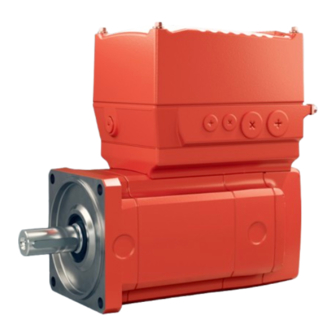
Page 169: Device Structure
Device structure MOVIMOT® performance drive unit Device structure MOVIMOT® performanc e drive unit ® MOVIMOT performance drive unit ® 7.1.1 MOVIMOT performance DAC with electronics cover size 1 ® MOVIMOT performance drive units consist of the 2 core components of the servomo- tor and the decentralized inverter (see following figure). - Page 170 Device structure MOVIMOT® performance drive unit ® 7.1.2 MOVIMOT performance DAC with electronics cover size 2 ® MOVIMOT performance drive units consist of the 2 core components of the servomo- tor and the decentralized inverter (see following figure). The decentralized inverter is referred to as the electronics cover in the following.
-
Page 171: Cable Entry Position
Device structure Cable entry position Cable entry position The device is equipped with the following cable bushings: Electronics cover • Position X, 1, 2, 3 size 1 – X: 2 × M25 × 1.5 + 2 × M16 × 1.5 –... - Page 172 Device structure Cable entry position ® 7.2.2 Overview of MOVIMOT performance DBC, DAC with electronics cover size 2 The following figure shows the possible cable entries: 35572058123 The position of the cable bushings depends on the position of the decentralized in- verter.
-
Page 173: Nameplate Position
Device structure Nameplate position Nameplate position ® The following nameplate positions are possible for MOVIMOT performance: • X (standard position) • The position of the nameplate depends on the position of the decentralized inverter. ® 7.3.1 Overview of MOVIMOT performance DBC, DAC The following figure shows an example of the position of the nameplates on the device: eff% 88,3... -
Page 174: Example Nameplate And Type Designation Of The Drive Unit
Device structure Example nameplate and type designation of the drive unit Example nameplate and type designation of the drive unit ® 7.4.1 MOVIMOT performance DAC nameplate The following figure shows an example of a drive unit nameplate. The format of the type designation can be found in chapter "Type designation ...". - Page 175 Device structure Example nameplate and type designation of the drive unit ® 7.4.2 Type designation of MOVIMOT performance DAC The following table shows the type designation of the drive unit. Series, 1st gear unit KAF = Gear unit (+ design) Size, 1st gear unit Series, 2nd gear unit R = Primary gear unit...
- Page 176 Device structure Example nameplate and type designation of the drive unit AZ2Z Option IV = Connector at the connection box PK = Temperature sensor ® AZ2Z = Multi-turn encoder with MOVILINK DDI connection ® EZ2Z = Single-turn encoder with MOVILINK DDI connection PE = Pressure compensation fitting electronics BW1 = Integrated BW1 braking resistor...
-
Page 177: Example Of The Optional Nameplate "Electrical Regulations Ul/Ce
Device structure Example of the optional nameplate "Electrical regulations UL/CE" Example of the optional nameplate "Electrical regulations UL/CE" ® The optional type plate "UL/CE Electrical Regulation" for MOVIMOT performance drive units is in preparation. Examples for the optional nameplate "Connector positions" 7.6.1 Design with electronics cover size 1 The following figure shows an example of the optional nameplate "Connector posi-... - Page 178 Device structure Examples for the optional nameplate "Connector positions" 7.6.2 Design with electronics cover size 2 The following figure shows an example of the optional nameplate "Connector posi- tions": The nameplate shows the designations and positions of the connectors at the connec- tion box.
-
Page 179: Electronics
Device structure Electronics Electronics 7.7.1 Overview of electronics cover Devices with the following electronics covers are available depending on the nominal output current: Electronics cover Nominal out- Type designation Size Image put current 2.0 A DAC...-0020.. Size 1 without cooling fins 2.5 A DAC...-0025.. - Page 180 Device structure Electronics 7.7.2 Connection box and electronics cover (internal) size 1 The following figure shows the connection box and the bottom side of the electronics cover: 3 5 6 [17] [18] [17] [18] [17] [18] [17] [16] [15] [14] [13] [12] [11] [10]...
- Page 181 Device structure Electronics 7.7.3 Connection box and electronics cover (internal) size 2 The following figure shows the connection box and the bottom side of the electronics cover: [16] [15] [14] [13] [12] [11] [10] [17] [17] [17] 35573102987 Cable glands Connection box Line connection L1, L2, L3 Connector connection unit for electronics cover...
- Page 182 Device structure Electronics 7.7.4 Electronics cover (outer) size 1 The following figure gives an example of electronics cover designs: 29317784459 "LED displays" (→ 2 346) "Potentiometer f1 (underneath the screw plug)" (→ 2 299) "Potentiometer f2 (underneath the screw plug)" (→ 2 301) "Connector" (→ 2 283) 7.7.5 Electronics cover (outer) size 2 The following figure gives an example of electronics cover designs: 36725585163 "LED displays" (→ 2 346)
-
Page 183: Example Nameplate And Type Designation Of Electronics
Device structure Example nameplate and type designation of electronics Example nameplate and type designation of electronics 7.8.1 Inner nameplate of DAC.. electronics cover The following figure gives an example of a nameplate of the electronics cover. For the structure of the type designation, refer to chapter "Type designation of the electronics cover ...". - Page 184 Device structure Example nameplate and type designation of electronics 7.8.3 Type designation of DAC.. electronics cover The following table shows the type designation of the electronics cover: DAC Product family DAC = Electronics cover Direct AS-Interface Communication Communication type 1 = AS-Interface Connection configuration 0 = M12 connector on electronics cover (standard) Communication version...
-
Page 185: Example Nameplate And Type Designation Of Connection Unit
Device structure Example nameplate and type designation of connection unit ® MOVIKIT version ® 000 = No MOVIKIT module loaded ex-works Operating mode options B = Brake control C = Specific customer identification D = Device-specific parameterization of the delivery state P = Customer-specific parameterization 7.8.4 Example: Nameplate of a replaceable memory module The following figure shows an example of the nameplate for the replaceable memory... - Page 186 Device structure Example nameplate and type designation of connection unit 7.9.2 Type designation of connection unit The following table shows the type designation of the connection unit: Product family CU = Connection unit (motor with electronics cover) Hardware design ® ®...
-
Page 187: Markings
Device structure Markings 7.10 Markings The following table shows an example of the markings on the nameplate. The CE marking indicates compliance with the following European direc- tives: • Low Voltage Directive 2014/35/EU • EMC Directive 2014/30/EU • Machinery Directive 2006/42/EC •... -
Page 188: Fs Logo Description
Device structure FS logo description 7.11 FS logo description The FS logo on the nameplate is based on the combination of safety-related compo- nents that is installed. The following FS logo variants are possible: Device with STO connection via terminals or connectors ®... -
Page 189: Mechanical Installation
Mechanical installation Installation notes Mechanical installation Installation notes Perform the following steps before installation: WARNING! Electric shock caused by dangerous voltages in the connection box. Severe or fatal injuries. De-energize the device. Pay attention to the 5 safety rules in chapter “Carrying out electrical work safely”. -
Page 190: Tolerances For Torque Ratings
Mechanical installation Tolerances for torque ratings Tolerances for torque ratings Adhere to the specified tightening torques with a tolerance of +/- 10%. Installation requirements Check that the following conditions have been met: • The information on the drive unit's nameplate must match the voltage supply sys- tem. -
Page 191: Setting Up The Drive Unit
Mechanical installation Setting up the drive unit Setting up the drive unit 8.6.1 Notes Pay attention to the following information when installing the drive unit: • Perform the steps described in chapter "Installation notes" (→ 2 189) before in- stalling the drive unit: •... - Page 192 Mechanical installation Setting up the drive unit 8.6.3 Electronics cover Installing the electronics cover Install the electronics cover as follows: WARNING! Risk of burns due to hot surfaces. Severe injuries. Let the device cool sufficiently before touching it. 2. NOTICE! Loss of the guaranteed degree of protection. Possible damage to prop- erty.
- Page 193 Mechanical installation Setting up the drive unit Removing the electronics cover Remove the electronics cover as follows: WARNING! Risk of burns due to hot surfaces. Severe injuries. Let the device cool sufficiently before touching it. 2. Undo the screws of the electronics cover. 3.
- Page 194 Mechanical installation Setting up the drive unit 8.6.7 Pressure compensation on electronics (option /PE) Fitting the provided pressure compensation fitting (option/PE) For designs with an included pressure compensation fitting (option /PE), install the fit- ting depending on the mounting position used. The tightening torque is 4.0 Nm. Pressure compensation fitting installation positions The following table shows the installation location-dependent mounting positions of the pressure compensation fitting (option/PE):...
-
Page 195: Tightening Torques
Mechanical installation Tightening torques Tightening torques ® 8.7.1 Example of MOVIMOT performance The following figure shows an example of the installation of the threaded blanking plugs, cable glands and electronics cover. The number and position of threaded blank- ing plugs and cable bushings depend on the ordered variant. 38412007947 Tighten the screws in diametrically opposite sequence with a tightening torque of 6.0 Nm (for size 1) or 9.5 Nm (for size 2). - Page 196 Mechanical installation Tightening torques 8.7.2 Tightening torques for cable glands Tighten cable glands optionally included delivery SEW‑EURODRIVE with the following torques: Screw fitting type Image Con- Size Tightening Outer Tight- Part num- tent torque diame- ening ter of force Thread Cable cable clamp-...
-
Page 197: Electrical Installation
Electrical installation Installation planning taking EMC aspects into account Electrical installation Installation planning taking EMC aspects into account 9.1.1 Notes on arranging and routing installation components The correct operation of decentralized inverters depends on selecting the correct cables, providing correct grounding, and on a properly functioning equipotential bond- ing. - Page 198 Electrical installation Installation planning taking EMC aspects into account Example with electronics cover size 1 The following figure shows the connection of the equipotential bonding and the PE conductor: [1] The mechanical installation of a drive unit with hollow shaft does not create a conductive connection of drive unit and mounting plate (e.g.
- Page 199 Electrical installation Installation planning taking EMC aspects into account Example with electronics cover size 2 The following figure shows the connection of the equipotential bonding and the PE conductor: [1] The mechanical installation of a drive unit with hollow shaft does not create a conductive connection of drive unit and mounting plate (e.g.
-
Page 200: Equipotential Bonding At The Connection Box
Electrical installation Equipotential bonding at the connection box Equipotential bonding at the connection box The following cable gland with an M6 threaded bolt provides an additional option for HF-compatible equipotential bonding on a connection box: 9007203139701899 Tightening torque Part number Cable gland M6 nut for stud bolt... -
Page 201: Installation Instructions
Electrical installation Installation instructions Installation instructions 9.3.1 Permitted voltage systems Information on voltage supply sys- Information on permissibility tems TN and TT systems – voltage sys- Use is possible without restrictions. tems with directly grounded star point IT systems – voltage systems with Operation with an electronics cover of size 1 non-grounded star point in IT system design is permitted (...-513-..)! - Page 202 Electrical installation Installation instructions Mounting of insulating bushing (only with electronics cover size 2) The electronics covers of size 2 are compatible with IT systems only if you mount an insulating bushing. When ordering the electronics cover, SEW‑EURODRIVE supplies the insulating bushing as a single item in an accessory bag, provided it has been se- lected separately.
- Page 203 Electrical installation Installation instructions 9.3.2 Connecting supply system cables Observe the following information when connecting the supply system cables: • The nominal voltage and frequency of the device must correspond with the data of the supply system. • Dimension the cable cross section according to the input current I for rated line power, see product manual >...
- Page 204 Electrical installation Installation instructions 9.3.4 Activating line terminals X1 Adhere to the following sequence when actuating the line terminals X1: 25649924107 9.3.5 Activating terminals X3 for the braking resistor Adhere to the following sequence when actuating the X3 terminals for the braking re- sistor: 25650172171 9.3.6...
- Page 205 Electrical installation Installation instructions 9.3.7 Selecting the residual current device The inverter can cause a direct current in the PE conductor. Proceed as follows to select the residual current device: 1. If using a residual current device is not mandatory according to the standards, SEW‑EURODRIVE recommends not using a residual current device.
- Page 206 Electrical installation Installation instructions 9.3.9 Notes on PE connection PE connection to devices with a lifting eye The handle is only used to transport the unit. The handle is not required for operation. 1. Remove the lifting eye. Store the lifting eye for future service work. WARNING! Electric shock due to faulty PE connection.
- Page 207 Electrical installation Installation instructions PE connection to devices with hoop guard The optional guard bracket is used to protect the connectors on the electronics cover. Do not remove the guard bracket. 1. Connect the PE cable to the guard bracket according to the following figure. 2.0 –...
- Page 208 Electrical installation Installation instructions Leakage currents During normal operation, leakage currents ≥ 3.5 mA may occur. In order to fulfill EN 61800-5-1, observe the following information: • The ground connection (PE) must be installed in such a way that it meets the re- quirements for systems with high leakage currents.
- Page 209 Electrical installation Installation instructions 9.3.12 Installation above 1000 m amsl The devices can be used at altitudes above 1000 m above sea level up to 3800 m above sea level under the following marginal conditions. The maximum altitude is lim- ited due to the decreased dielectric strength at lower air density. •...
-
Page 210: Installation Topologies
Electrical installation Installation topologies Installation topologies 9.4.1 Installation topology (example: standard installation) following figure shows basic installation topology with ® MOVIMOT performance: Safety relay Supply system Optional AS-Interface Master AS-Interface Back-up AUX-PWR (24 V) fuse/line protection Control cabinet level Field level DAC.. -
Page 211: Movimot® Performance Dac Terminal Assignment
Electrical installation MOVIMOT® performance DAC terminal assignment MOVIMOT® performanc e DAC terminal assignment ® MOVIMOT performance DAC terminal assignment Attach units without a connector to the terminals as follows: WARNING! Electric shock caused by dangerous voltages in the connection box. - Page 212 Electrical installation MOVIMOT® performance DAC terminal assignment 9.5.2 Connection box size 2 ® The following figure shows the terminals of MOVIMOT performance DAC, size 2: 11 12 13 14 15 16 21 22 23 24 25 26 11 12 13 9.5.3 Assignment ®...
- Page 213 Electrical installation MOVIMOT® performance DAC terminal assignment Terminal Marking Function yellow F_STO_P1 Input STO+ control termi- yellow F_STO_P1 Input STO+ nals (to loop through) – 0V24_OUT 0V24 reference potential for DC 24 V output – 24V_OUT DC 24 V output – DI01 Digital input DI01 –...
- Page 214 Electrical installation MOVIMOT® performance DAC terminal assignment These jumpers are not present in the following designs: • Designs with connectors with STO function Additional information is available in the product manual > chapter "Project planning for functional safety" and chapter "Connection variants functional safety". ®...
-
Page 215: Electrical Installation - Functional Safety
Electrical installation Electrical installation – functional safety Electrical installation – functional safety 9.6.1 Installation instructions WARNING Only the types of connection described in this documentation may be used. Severe or fatal injuries. • Non-compliant connection variants specified in other documentation are not per- missible. - Page 216 Electrical installation Electrical installation – functional safety Requirements Use of safety relays The requirements of the manufacturers of safety relays (such as protecting the output contacts against welding) or of other safety components must be strictly observed. The basic requirements for cable routing apply as described in this documentation. For connecting the device to the safety relays, observe the installation requirements in accordance with chapter "Installation requirements" (→ 2 161).
- Page 217 Electrical installation Electrical installation – functional safety Switching off the STO signal for several drive units (STO group disconnection) The STO signal for several drive units can be provided by a single safety relay. The following requirements must be met: •...
- Page 218 Electrical installation Electrical installation – functional safety Wiring diagrams of the connection variants STO connection at terminal X9 For detailed information on terminal X9, refer to chapter "Electrical Installation" > "Ter- minal assignment". Delivery state In the delivery state, the following terminals are bridged on STO connection X9. The jumpers are marked with the text "Caution, remove jumper for safety operation".
- Page 219 Electrical installation Electrical installation – functional safety Two-pole sourcing/sinking output Example 1 F_STO_P1 F-DO_P F_STO_M F-DO_M F_STO_P2 F_STO_P1 0V24_OUT 24 V_OUT F_STO_M F_STO_P2 9007222818872587 [1] Drive unit [2] External safety device Example 2 F_STO_P1 F_STO_M F_STO_P2 F_STO_P1 0V24_OUT 24 V_OUT F_STO_M F_STO_P2 34106433163 [1] Drive unit [2] External safety device...
- Page 220 Electrical installation Electrical installation – functional safety Two-channel serial sourcing output 24 V F-DOR_11 F-DOR_12 F-DOR_21 F_STO_P1 F-DOR_22 F_STO_M F_STO_P2 F_STO_P1 0V24_OUT 24 V_OUT F_STO_M F_STO_P2 9007222818944907 [1] Drive unit [2] External safety device Single-pole sourcing output F_STO_P1 F-DO_P F_STO_M F_STO_P2 F_STO_P1 0V24_OUT...
- Page 221 Electrical installation Electrical installation – functional safety STO group disconnection, two-pole, sourcing output F_STO_P1 F-DO_P1 F_STO_M F_STO_P2 F-DO_P2 F_STO_P1 F_STO_M F_STO_P2 0V24_OUT 24 V_OUT F_STO_P1 F_STO_M F_STO_P2 F_STO_P1 F_STO_M F_STO_P2 0V24_OUT 24 V_OUT 25228151435 [1] Drive unit [2] External safety controller ®...
- Page 222 Electrical installation Electrical installation – functional safety STO group disconnection, two-pole, sourcing/sinking output F_STO_P1 F-DO_P F_STO_M F-DO_M F_STO_P2 F_STO_P1 F_STO_M F_STO_P2 0V24_OUT 24 V_OUT F_STO_P1 F_STO_M F_STO_P2 F_STO_P1 F_STO_M F_STO_P2 0V24_OUT 24 V_OUT 25228157067 [1] Drive unit [2] External safety controller ®...
- Page 223 Electrical installation Electrical installation – functional safety STO group disconnection, two-channel, serial sourcing output 24 V F-DOR_11 F-DOR_12 F-DOR_21 F_STO_P1 F-DOR_22 F_STO_M F_STO_P2 F_STO_P1 F_STO_M F_STO_P2 0V24_OUT 24 V_OUT F_STO_P1 F_STO_M F_STO_P2 F_STO_P1 F_STO_M F_STO_P2 0V24_OUT 24 V_OUT 25229441035 [1] Drive unit [2] External safety controller ®...
- Page 224 Electrical installation Electrical installation – functional safety STO group disconnection, one-pole, sourcing output F_STO_P1 F-DO_P F_STO_M F_STO_P2 F_STO_P1 F_STO_M F_STO_P2 0V24_OUT 24 V_OUT F_STO_P1 F_STO_M F_STO_P2 F_STO_P1 F_STO_M F_STO_P2 0V24_OUT 24 V_OUT 25229445003 [1] Drive unit [2] External safety controller STO connection via M12 connector X5504/X5505 For further information on the connection of X5504/X5505, refer to the product manual >...
- Page 225 Electrical installation Electrical installation – functional safety Two-pole sourcing output X5504 F_STO_P2 F-DO_P2 F_STO_M F_STO_P1 F-DO_P1 23876274315 [1] Drive unit [2] External safety device ® Product Manual – MOVIMOT performance DAC...
- Page 226 Electrical installation Electrical installation – functional safety Two-pole sourcing/sinking output Example 1 X5504 F_STO_P2 F-DO_P F_STO_M F-DO_M F_STO_P1 23876260491 [1] Drive unit [2] External safety device Example 2 X5504 24V_OUT F_STO_P2 0V24_OUT F_STO_M F_STO_P1 34216188171 [1] Drive unit [2] External safety device Observe the following information: •...
- Page 227 Electrical installation Electrical installation – functional safety Two-channel serial sourcing output 24 V F-DOR_11 X5504 F-DOR_12 F-DOR_21 F_STO_P2 F-DOR_22 F_STO_M F_STO_P1 23875551243 [1] Drive unit [2] External safety device Single-pole sourcing output X5504 F_STO_P2 F-DO_P F_STO_M F_STO_P1 23875545995 [1] Drive unit [2] External safety device ®...
- Page 228 Electrical installation Electrical installation – functional safety STO group disconnection, two-pole, sourcing/sinking output X5504 F_STO_P2 F-DO_P F_STO_M F-DO_M F_STO_P1 X5505 F_STO_P2 F_STO_M F_STO_P1 X5504 F_STO_P2 F_STO_M F_STO_P1 X5505 F_STO_P2 F_STO_M F_STO_P1 9007223142162187 [1] Drive unit [2] External safety device STO jumper plug (three-pin) WARNING Safe disconnection of the device is not possible when the jumper plug is used.
- Page 229 Electrical installation Electrical installation – functional safety WARNING Disabling of the safety-related disconnection of further devices due to parasitic voltages when using an STO jumper plug. Severe or fatal injuries. • Only use the STO jumper plug when all incoming and outgoing STO connections have been removed from the device.
-
Page 230: Movimot ® Performance Dac Wiring Diagram
Electrical installation MOVIMOT® performance DAC connection diagram MOVIMOT® performanc e DAC connection diagram ® MOVIMOT performance DAC wiring diagram The following figure shows the connections of the device: F11/F12/F13 ® MOVIMOT performance Line terminals CM3C../DAC Braking resistor Engineering interface Control terminals AS-Interface X4271 32273456011... -
Page 231: Cable Routing And Cable Shielding
Electrical installation Cable routing and cable shielding Cable routing and cable shielding 9.8.1 Accessory bag with installation equipment (part number 18241395) INFORMATION For some installation variants, you do not need all the parts of the accessory kit. The delivery of each drive unit includes the following accessory bag with installation materials for cable shielding (exception: Does not apply when all possible connections were ordered in connector design): •... - Page 232 Electrical installation Cable routing and cable shielding 9.8.2 General installation options The following chapters show common examples and contain important notes on cable selection and cable routing. Assembly of installation materials The following image illustrates the assembly of the installation material: Size 2 Size 1 ®...
- Page 233 Electrical installation Cable routing and cable shielding 9.8.3 Installation with separately routed AS-Interface/AUX-PWR cable Notes on cable routing and shielding – Recommended cable routing Note the following points for cable routing and cable shielding: • Cable selection – When selecting cables, observe the recommended connection cables in the product manual >...
-
Page 234: Emc Cable Glands
Electrical installation EMC cable glands EMC cable glands 9.9.1 Cable shielding (alternative) As an alternative to using shield clamps for shielded cables (e.g. control cables, STO cables, power cables), you can use EMC cable glands, which are available as an op- tion, to connect the shield. -
Page 235: Connectors
Electrical installation Connectors 9.10 Connectors 9.10.1 Representation of connections The connection diagrams of the connectors depict the contact end of the connections. 9.10.2 Connection cables INFORMATION For more information about cable types, see chapter "Technical data". Connection cables are not included in the scope of delivery. Prefabricated cables for connecting SEW‑EURODRIVE components are available to order. - Page 236 Electrical installation Connectors Cable routing Observe the permitted bending radii of the cables used when routing the cables. Fur- ther information can be found in the product manual > chapter "Technical data" > "Di- mension drawings of connectors of the connection box" > "Connectors including mat- ing connectors" (→ 2 104).
- Page 237 Electrical installation Connectors ® 9.10.3 MOVIMOT performance DAC drive unit size 1 connector positions The following figure shows possible connector positions: X1523 X2304 X1524 X4142 X5135 X5505 X5504 X1523 X5135 X1524 X4142 X5504 X5505 X2304 X2242 X1206 X5136 X1203_2 X1203_1 X1207 X2328 X1217...
- Page 238 Electrical installation Connectors Connectors Not together at a position with the Designation Coding ring/ Function Position connector: color • X1206 X1203_1 Black "AC 400 V connection" (→ 2 249) X, 2 or 3 • X1207 • X1217 X1203_2 Black "AC 400 V connection" (→ 2 249) X, 2 or 3 •...
- Page 239 Electrical installation Connectors Connectors Not together at a position with the Designation Coding ring/ Function Position connector: color • X5505 X1524 Black "DC 24 V backup voltage – in- X, 2 or 3 put" (→ 2 280) • X1523 (AUX-PWR) • X4142 X4142 "Engineering interface" (→ 2 281) X, 2 or 3 •...
- Page 240 Electrical installation Connectors ® 9.10.4 MOVIMOT performance DAC drive unit size 2 connector positions Cable bushing M25 The following figure shows possible connector positions: X1206 X1203_2 X1203_1 X1217 X1207 X5136 X1206 X1203_1 X1203_2 X1207 X1217 X5136 X1203_2 X1203_1 X1206 X1217 X1207 X5136 36697561099...
- Page 241 Electrical installation Connectors Connector Not together at a position with the Designation Coding ring/ Function Position connector: color • X1206 X1203_1 Black "AC 400 V connection" (→ 2 249) X, 2 or 3 • X1207 • X1217 X1203_2 Black "AC 400 V connection" (→ 2 249) X, 2 or 3 •...
- Page 242 Electrical installation Connectors Cable bushing M16 The following figure shows possible connector positions: X1523 X5135 X1524 X4142 X2304 X5505 X5504 X5504 X5505 X2304 X5135 X4142 X1523 X1524 X5504 X5505 X2304 X4142 X1523 X1524 X5135 9007235954791947 Connectors Not together at a position with the Designation Coding ring/...
- Page 243 Electrical installation Connectors Connectors Not together at a position with the Designation Coding ring/ Function Position connector: color • X5505 X1523 Light gray "DC 24 V backup voltage – in- X, 2 or 3 put" (→ 2 276) • X4142 • X1524 X1524 Black "DC 24 V backup voltage" (→ 2 280) X, 2 or 3 •...
- Page 244 Electrical installation Connectors 9.10.6 Connector variants M12 connector at the connection box M12 connectors at the connection box are pre-installed at delivery so they match the connection cables provided by SEW‑EURODRIVE. Customers can adjust the align- ment of connectors if required. The following figure shows a schematic illustration with the permitted tightening torque: 6 Nm...
- Page 245 Electrical installation Connectors M12 connector with mating connector at connection box or electronics cover The following figure shows a schematic illustration with the permitted tightening torques: 0.4 – 0.6 Nm 32845364363 INFORMATION The M12 connectors are usually tightened with a torque of 0.4 – 0.6 Nm. Observe the data sheet of the used prefabricated cables.
- Page 246 Electrical installation Connectors ® Examples of MOVIMOT performance The following figure shows the installation of the straight and angled M23 connector: 2 mm 3 Nm 30851321099 "Straight" design "Right-angle" design Tightening torque of the union nut 3 Nm You can order suitable tools from TE Connectivity – Intercontec products: •...
- Page 247 Electrical installation Connectors 9.10.7 Using connectors assembled by yourself M23 connector by TE connectivity – Intercontec Products The power connectors for assembling connection cables yourself, and the correspond- ing assembly tool set is available for order from TE Connectivity - Intercontec products.
- Page 248 Electrical installation Connectors Mini-I/O connector The following tables contains the part numbers and purchase order numbers of the mini-I/O connectors for customer assembly of mini I/O connection cables. Connector type Cable Cable Purchase order num- Part number Outer diameter Category SEW‑EURODRIVE Core cross section TE Connectivity...
-
Page 249: Optional Connector Assignment
The following table provides information about this connection: Function AC 400 V connection for supplying the device/for looping through Connection type M23, SEW-EURODRIVE insert, Series 723, SpeedTec equipment, company: TE Connectivity – Intercontec products, female, coding ring: black, protected against contact Connection diagram... - Page 250 Electrical installation Optional connector assignment Connection cables Cable cross section 1.5 mm The following table shows the cables available for this connection: Connection cable Conformity/ Cable type Length/in- Cable part num- stallation cross sec- type tion/operat- ing voltage ® HELUKABEL Variable 1.5 mm JZ-600...
- Page 251 Electrical installation Optional connector assignment Connection cable Conformity/ Cable type Length/in- Cable part num- stallation cross sec- type tion/operat- ing voltage ® HELUKABEL Variable 2.5 mm ® MULTIFLEX 18153275 – 512 AC 500 V M23, coding M23, coding ring: black, ring: black, male male ®...
- Page 252 Electrical installation Optional connector assignment Cable cross section 4.0 mm The following table shows the cables available for this connection: Connection cable Conformity/ Cable type Length/in- Cable part num- stallation cross sec- type tion/operat- ing voltage ® HELUKABEL Variable 4.0 mm ®...
- Page 253 Electrical installation Optional connector assignment Connection cable Conformity/ Cable type Length/in- Cable part num- stallation cross sec- type tion/operat- ing voltage ® HELUKABEL Variable 4.0 mm ® TOPFLEX – 18133983 611-PUR AC 500 V (halogen-free) M23, coding Open ring: black, male ® HELUKABEL Variable 4.0 mm –...
- Page 254 Electrical installation Optional connector assignment Connection of cables with open end The following table shows the core assignment of cables with the following part num- bers: Part numbers 18180094, 18127479, 18133967, 18153283, 18153291, 18127495, 18133983, 18153321, 18153348 Assembly Open cable end Description Prefabricated con- nector...
- Page 255 Electrical installation Optional connector assignment 9.11.2 X1206: AC 400 V connection (IN) The following table provides information about this connection: Function AC 400 V connection (IN) Connection type M15-X-Power, male, connector without union nut, (current load max. 16 A) Connection diagram Assignment Contact Function...
- Page 256 Electrical installation Optional connector assignment 9.11.3 X2242: AC 400 V connection (OUT) The following table provides information about this connection: Function AC 400 V connection (OUT) Connection type M15-X-Power, female, connector with union nut, (current load max. 16 A) Connection diagram Assignment Contact Function...
- Page 257 Electrical installation Optional connector assignment 9.11.4 X1207: AC 400 V connection (IN) INFORMATION The number of permitted plug-in cycles for this connector is 10 times. The following table provides information about this connection: Function AC 400 V connection (IN) Connection type QPD W 4PE2,5, QUICKON connector, coding 3, male, PhoenixContact Connection diagram Assignment...
- Page 258 Electrical installation Optional connector assignment 9.11.5 X1217: PA connection for AC 400 V and 24 V backup voltage (IN) The following table provides information about this connection: Function PA connection for AC 400 V and DC 24 V backup voltage (IN) Connection type MQ15-X-Power, male, connector without union nut, MURR Elektronik, (current load max.
- Page 259 Electrical installation Optional connector assignment 9.11.6 X2328: PA connection for AC 400 V and 24 V backup voltage (OUT) The following table provides information about this connection: Function PA connection for AC 400 V and DC 24 V backup voltage (OUT) Connection type MQ15-X-Power, female, connector with union nut, MURR Elektronik, (current load max.
- Page 260 Electrical installation Optional connector assignment 9.11.7 X5504: STO (3 cores) WARNING No safe disconnection of the device. Severe or fatal injuries. • You may bridge the STO connection with 24 V only if the device is not intended to fulfill any safety functions. The following table provides information about this connection: Function Connection for safe disconnection (STO, 3-core)
- Page 261 Electrical installation Optional connector assignment Connection cables INFORMATION Use only shielded cables for this connection and only suitable connectors that con- nect the shield with the device in an HF-capable manner. The following table shows the cables available for this connection: Connection cable Conformity/ Cable type...
- Page 262 Electrical installation Optional connector assignment Connection cable Conformity/ Cable type Length/in- Cable part num- stallation cross sec- type tion/operat- ing voltage CE/UL: igus chainflex Variable 4 × 0.5 mm CF78.UL 28110994 Shielded DC 60 V M12, 5‑pin, M12, 5‑pin, A‑coded, fe- A‑coded, male male CE/UL: igus chainflex...
- Page 263 Electrical installation Optional connector assignment Connection of cables with open end ® HELUKABEL The following table shows the core assignment of cables with the following part num- bers: Part numbers 28110978, 28110943 Assembly Open cable end Description Assembled con- nector Core Identifi- Assembly...
- Page 264 Electrical installation Optional connector assignment igus chainflex The following table shows the core assignment of cables with the following part num- bers: Part numbers 28111001, 28111036 Assembly Open cable end Description Assembled con- nector Core Identifi- Assembly Signal Contact color/ cation core cross section...
- Page 265 Electrical installation Optional connector assignment 9.11.8 X5505: STO (3 cores) WARNING Disabling of the safety-related disconnection of further devices due to parasitic voltages when using an STO jumper plug. Severe or fatal injuries. • Only use the STO jumper plug when all incoming and outgoing STO connections have been removed from the device.
- Page 266 Electrical installation Optional connector assignment Connection cables INFORMATION Use only shielded cables for this connection and only suitable connectors that con- nect the shield with the device in an HF-capable manner. The following table shows the cables available for this connection: Connection cable Conformity/ Cable type...
- Page 267 Electrical installation Optional connector assignment Connection cable Conformity/ Cable type Length/in- Cable part num- stallation cross sec- type tion/operat- ing voltage CE/UL: igus chainflex Variable 4 × 0.5 mm CF78.UL 28110994 Shielded DC 60 V M12, 5‑pin, M12, 5‑pin, A‑coded, fe- A‑coded, male male CE/UL: igus chainflex...
- Page 268 Electrical installation Optional connector assignment Connection of cables with open end ® HELUKABEL The following table shows the core assignment of cables with the following part num- bers: Part numbers 28117808, 28110986 Assembly Open cable end Description Assembled con- nector Core Identifi- Assembly...
- Page 269 Electrical installation Optional connector assignment igus chainflex The following table shows the core assignment of cables with the following part num- bers: Part numbers 28117816, 28111044 Assembly Open cable end Description Assembled con- nector Core Identifi- Assembly Signal Contact color/core cation cross sec- tion...
- Page 270 Electrical installation Optional connector assignment 9.11.9 X2304: Connection of external braking resistor The following table provides information about this connection: Function Connection of external braking resistor Connection type M12, 4-pin, female, S-coded Wiring diagram Assignment Contact Function Braking resistor connection + res.
- Page 271 Electrical installation Optional connector assignment Connection of cables with open end The following table shows the core assignment of cables with the following part num- bers: Part numbers 28172558 Assembly Open cable end Description Assembled con- nector Conductor Mark- Assembly Signal Contact color/core...
- Page 272 Electrical installation Optional connector assignment 9.11.10 X5135: Digital inputs The following table provides information about this connection: Function Digital inputs Connection type M12, 5-pin, female, A-coded, color: black Connection diagram Assignment Contact Function +24 V DC 24 V sensor supply DI02 Digital input DI02 0V24 0V24 reference potential for sensors DI01...
- Page 273 Electrical installation Optional connector assignment 9.11.11 X5136: Digital inputs, relay output The following table provides information about this connection: Function Digital inputs, relay output Connection type M23, female, male thread, TE Connectivity-Intercontec products, P insert, SpeedTec equipment, 12‑pin, 0°-coded, coding ring: without, protected against contact Connection diagram Assignment Contact...
- Page 274 Electrical installation Optional connector assignment Connection cable INFORMATION Use only shielded cables for this connection and only suitable connectors that con- nect the shield with the device in an HF-capable manner. The following table shows the cables available for this connection: Connection cable Conformity/ Cable type...
- Page 275 Electrical installation Optional connector assignment Connection of cables with open end The following table shows the core assignment of cables with the following part num- bers: Part numbers 11741457 Assembly Open cable end Description Prefabricated con- nector Core Identifi- Assembly Signal Contact color/...
- Page 276 Electrical installation Optional connector assignment 9.11.12 X1523: DC 24 V backup voltage, input The following table provides information about this connection: Function Input DC 24 V backup voltage Connection type M12, 5‑pin, male, L‑coded, color: light gray Connection diagram Assignment Contact Function +24V/L1 DC 24 V input/L1 (for backup mode) 0V24/N2 0V24 reference potential/N2...
- Page 277 Electrical installation Optional connector assignment Connection cables The following table shows the cables available for this connection: Connection cable Conformity/ Cable type Length/in- Cable part num- stallation cross sec- type tion/operat- ing voltage ® HELUKABEL Variable 5 × 2.5 mm JZ-500 28114345 DC 60 V M12, 5‑pin,...
- Page 278 Electrical installation Optional connector assignment Connection cable Conformity/ Cable type Length/in- Cable part num- stallation cross sec- type tion/operat- ing voltage ® CE/UL: HELUKABEL Variable 5 × 2.5 mm Li9Y11Y-HF 28114353 DC 60 V M12, 5‑pin, M12, 5‑pin, L‑coded, fe- L‑coded, male male ®...
- Page 279 Electrical installation Optional connector assignment Connection of cables with open end The following table shows the core assignment of cables with the following part num- bers: Part numbers 28117786 Assembly Open cable end Description Prefabricated con- nector Core Identi- Assembly Signal Contact color/...
- Page 280 Electrical installation Optional connector assignment 9.11.13 X1524: DC 24 V backup voltage, input (AUX-PWR) The following table provides information about this connection: Function Input of DC 24 V backup voltage / DC 24 V supply (AUX-PWR) Connection type M12, 4-pole, male, A-coded, color: black Connection diagram Assignment Function +24 V...
- Page 281 DC 24 V auxiliary output 0V24_OUT 0V24 reference potential CAN_H CAN High connection CAN_L CAN Low connection 1) Only use this output to supply components from SEW‑EURODRIVE. 2) Only use this output to supply components from SEW-EURODRIVE. ® Product Manual – MOVIMOT performance DAC...
- Page 282 Electrical installation Optional connector assignment Connection cables The following table shows the cables available for this connection: Connection cable Conformity/ Length/in- Operating part num- stallation voltage type Connection to USM21A interface adapter: 3.0 m DC 60 V USK15A 28139038 M12-SPEED- RJ10 CON, 5-pin, B‑coded, male Connection to CBG..
-
Page 283: Connector Assignment At The Electronics Cover
Electrical installation Connector assignment at the electronics cover 9.12 Connector assignment at the electronics cover For the positions of the connectors, refer to chapter "Electrical installation" > "Con- nector positions at the electronics cover..". 9.12.1 X4271: AS-Interface The following table provides information about this connection: Function AS-Interface Connection type... -
Page 284: Pc Connection
Electrical installation PC connection 9.13 PC connection Connect the PC to the drive unit before you start the engineering software ® MOVISUITE You have several options to connect a PC to the drive unit. Observe the information in the product manual > chapter "Electrical installation" > "PC connection"... - Page 285 Electrical installation PC connection Connection to X4142 (M12 at the connection box) The engineering interface X31 at the connection unit in the connection box is assigned to the internal wiring of X4142 connector. Connection without extension cable X4142 32385960459 Connection with extension cable X4142 41080931979...
- Page 286 Electrical installation PC connection Installing the included engineering X4142 connector SEW‑EURODRIVE supplies the engineering X4142 connector in some cases in an accessory bag (part number: 28273273) with the drive unit. In this case, install the en- gineering X4142 connector to the connection box of the drive unit as follows: 1.
- Page 287 Electrical installation PC connection Connection to X31 (RJ10 in the connection box) NOTICE Connector X31 provides a 24 V supply voltage for operating the connected options. Damage to connected options with low nominal voltage. • Only connect options with a nominal voltage of 24 V to connector X31, such as: –...
- Page 288 Electrical installation PC connection 9.13.2 Connection via keypad You can establish a connection between the PC and the device's engineering inter- face using the CBG22A, CBG21A, CBG11A or CBM22A keypads. The data is transferred according to the USB 2.0 standard. It is also possible to work with a USB 3.0 interface.
- Page 289 Electrical installation PC connection Connection to X4142 (M12 at the connection box) X4142 32386058507 Connection cable USB A/USB 2.0 Mini B (available for delivery from SEW‑EURODRIVE, part number: 25643517) Keypad CBG22A, CBG21A, or CBG11A Connection cable D-Sub/M12 (USK25A) (available for delivery from SEW‑EURODRIVE, part number: 28139046) ®...
- Page 290 Electrical installation PC connection Connection to X31 (RJ10 in the connection box) NOTICE Connector X31 provides a 24 V supply voltage for operating the connected options. Damage to connected options with low nominal voltage. • Only connect options with a nominal voltage of 24 V to connector X31, such as: –...
- Page 291 Electrical installation PC connection Installation housing CBM22A connection with integrated keypad to X4142 (M12 at connection box) X4142 35684595211 Installation housing CBM22A with integrated keypad ® Product Manual – MOVIMOT performance DAC...
-
Page 292: Startup
Startup Startup notes Startup 10.1 Startup notes Perform the following steps before startup: WARNING! Electric shock caused by dangerous voltages in the connection box. Severe or fatal injuries. De-energize the device. Pay attention to the 5 safety rules in chapter "Carrying out electrical work safely". - Page 293 Startup Startup notes 10.1.1 Lifting applications Perform the following additional steps before starting up the lifting applications: WARNING! Danger from falling hoist. Severe or fatal injuries. Observe the following information. ð Do not use the device alone as a safety device for the lifting application. ð...
- Page 294 Startup Startup notes ð "Initialization value": With the "Torque preload" parameter, you can specify the load torque to the speed controller as the initial value in the range -1000% – 1000% of the nominal motor torque. You can set this parameter during startup or optimization of the drive.
- Page 295 Startup Startup notes Parameter settings: • For vertical drives, use the setpoint/stop function (FCB05 - speed control). Func- tions > Drive functions > FCB 05 Speed control > Stop by setpoint function > Acti- vation = "1" (Yes). – Set the parameter Functions > Drive functions > FCB 05 Speed control > Stop by setpoint function >...
-
Page 296: Startup Requirements
Startup Startup requirements 10.2 Startup requirements NOTICE Gear unit overload. Damage to the gear unit. • Observe the peak torque of the gear unit when you configure the current limit and torque limit. • Check the current limits and torque limits and adjust them, if necessary. Startup is only required when you need to change the factory set parameterization. -
Page 297: Parameterization Mode
Startup Parameterization mode 10.3 Parameterization mode The following parameterization modes are available to perform the device startup: Easy mode Easy startup with predefined control interface. • Setting parameters, setpoints, and additional functions can only be set using the mechanical setting elements (potentiometer and DIP switch) at the device. •... -
Page 298: Control Elements
Startup Control elements 10.4 Control elements 10.4.1 Overview of control elements The following figure gives an overview of the control elements at the electronics cover. Size 1 S1 1 2 3 4 1 2 3 4 S2 S1 1 2 3 4 3 4 1 2 3 1 2 3 4 S2 4 S2... - Page 299 Startup Control elements 10.4.2 Potentiometer f1 NOTICE Loss of the ensured degree of protection if the screw plug of the potentiometer is not installed or not installed correctly. Damage to the device. • After setting the setpoint, make sure the screw plug of the potentiometer has a seal and screw it in.
- Page 300 Startup Control elements Parameter application limit speed The following table shows the default setting of the Application limit speed parameter: Startup Drive unit Default setting pa- rameter Application limit speed ® Automatic MOVIMOT performance 2000 min startup via the digital interface Perform The parameter Application limit speed is not changed during start- manual startup...
- Page 301 Startup Control elements 10.4.3 Potentiometer f2 NOTICE Loss of the ensured degree of protection if the screw plug of the potentiometer is not installed or not installed correctly. Damage to the device. • After setting the setpoint, make sure the screw plug of the potentiometer has a seal and screw it in.
- Page 302 Startup Control elements Parameter application limit speed The following table shows the default setting of the Application limit speed parameter: Startup Drive unit Default setting pa- rameter Application limit speed ® Automatic MOVIMOT performance 2000 min startup via the digital interface Perform The parameter Application limit speed is not changed during start- manual startup...
-
Page 303: Dip Switches
Startup DIP switches 10.5 DIP switches 10.5.1 Overview NOTICE Damage to the DIP switches caused by unsuitable tools. Damage to property. • Set the DIP switches only using suitable tools, such as a slotted screwdriver with a blade width of ≤ 3 mm. •... - Page 304 Startup DIP switches DIP switch S1 The following table shows the functions of DIP switch S1: DIP switch Meaning Direction of Release brake/ Speed moni- Reserved rotation re- deactivate toring deacti- ® versal DynaStop vation with FCB01 – enable Speed monitor- Speed moni- toring 1) The factory settings are shown in boldface.
- Page 305 Startup DIP switches 10.5.2 Description of the DIP switches DIP switch S1/1: Reversing the direction of rotation INFORMATION The direction of rotation is reversed depending on the setting of the DIP switch and of the parameter drive train 1 > Controller > Direction of rotation reversal. If both set- tings are active, the speed setpoint is not inverted (logical XOR).
- Page 306 Startup DIP switches DIP switch S1/3: Deactivating the speed monitoring INFORMATION If the function of this DIP switch is deactivated via parameter access, the last active setting of the relevant parameter is maintained. This DIP switch is used to disable speed monitoring. •...
-
Page 307: Startup With "Ex Works Parameters
Startup Startup with "ex works parameters" DIP switch Station type Station profile S2/2 S2/3 S2/4 Reserved 1) Defined by the address of the station. 2) The S-7.A.A profile (8 DI/8 DO) is designed by AS‑Interface for analog data transmission, which is why the data bits in the PLC are located in the data blocks for analog data. -
Page 308: Application-Related Startup
Startup Application-related startup 10.8 Application-related startup ® The applications are started up with specific settings using the MOVISUITE engineer- ing software. Pay attention to the information in the Product manual > chapter "Startup" > "Applica- tion-related startup", including the sub-chapters. 10.8.1 Pumps and fans Observe the following information:... - Page 309 Startup Application-related startup 10.8.3 Prioritized terminal control Description The "Prioritized terminal control" function is a control function that prioritizes control of the drive independently of the parameterized control signal source (e.g. fieldbus) via digital inputs. Operating behavior Firmware version 12 of the basic device covers the different operating behaviors of previous firmware versions.
- Page 310 Startup Application-related startup Safety option Parameter Operating behavior setting Safety card Interrupt F-commu- When activating the prioritized terminal control, F-communica- with nication tion with the safety card is stopped. safe inputs = YES (default) The communication timeout of the safety card activates the safety sub-functions and inhibits the drive.
- Page 311 Startup Application-related startup Functions Edge detection after STO and power ON The Edge detection after STO and power on parameter specifies whether the priorit- ized terminal control is started after the deactivation of the safety sub-function or with a power switch-on by the signal level or by a positive signal edge. All other states are evaluated only via the signal level.
- Page 312 Startup Application-related startup Speed source The Speed source parameter defines the behavior of safe communication with the higher-level safety controller when the prioritized terminal control is activated. Parameter Setting Meaning Speed Prioritized The "Prioritized terminal control" func- source terminal control – tion applies the speed from the follow- speed setpoint...
-
Page 313: Startup With Movisuite Engineering Software
Startup Startup with MOVISUITE® engineering software Signal at Setting Operating behavior digital input Prioritized Edge detection If the prioritized terminal control has been terminal control – after STO and activated by a digital input signal, the con- positive direction POWER ON troller enables the drive in positive direc- of rotation = signal level... -
Page 314: 10.10 Startup With The Cbg21A Keypad
Startup Startup with the CBG21A keypad The motor is started up in drive train 1. When using a motor from SEW‑EURODRIVE, select the motor type from the catalog or enter the nameplate. You can perform the startup for motors and encoders from SEW‑EURODRIVE with an electronic nameplate based on the data contained there. - Page 315 Startup Startup with the CBG21A keypad 10.10.1 CBG21A keypad The following figure shows the CBG21A keypad: 9007225148764555 Color display 4 function keys that are assigned according to the context. The assigned func- tions are shown in the color display above the keys. a = Permanently assigned with Back/Next b = Navigate in the menu c = Manual mode control section...
- Page 316 Startup Startup with the CBG21A keypad Symbols used The available functions are shown with pictograms in the keypad display. Manual operation Optimization of the control mode Application Diagnostics Parameter Data management Settings Back Next ® Product Manual – MOVIMOT performance DAC...
-
Page 317: 10.11 Startup With The Cbg11A Keypad
Startup Startup with the CBG11A keypad 10.11 Startup with the CBG11A keypad Using the CBG11A keypad, startup can be performed intuitively guided by the sym- bols and functions of the color display. Further information can be found in the product manual > chapter "Startup" > "Start- up with the CBG11A keypad", including the sub-chapters. - Page 318 Startup Startup with the CBG11A keypad 1. Change the digit within a number by using the <left/right> arrow keys. 2. The editable digit is underlined. 3. Change the value of the digit by using the <up/down> arrow keys. 4. Confirm the number with the <OK> key. Symbols used The available functions are shown with pictograms in the keypad display.
-
Page 319: 10.12 Process Data Configuration
Startup Process data configuration 10.12 Process data configuration In Easy mode the following process data configuration is active. In Expert mode, you can assign different functions to the individual data bits. 1) Easy mode is only available up to firmware version < 11. 10.12.1 Control word 1 Control word 1 –... - Page 320 Startup Process data configuration 10.12.2 Status word 1 Status word 1 – Cyclic data bits of the AS-Interface Function Usable data width of the AS- (AS- (Device) interface Interface) Slave profile DI 0 Ready for operation 4 bits 8 bits DI 1 Local mode/manual mode active DI 2 DI 01 DI 3...
- Page 321 Startup Process data configuration 10.12.3 Control word 2 INFORMATION You can configure the switch-on state of the parameter bits in the slave configuration in the AS-Interface master. The default setting of the value of the parameter bits is usually "1". Control word 2 – Acyclic parameter bits of the AS-Interface Function Usable data width of the AS-...
-
Page 322: Deactivating Dynastop ® For The Startup Procedure
Startup Disabling DynaStop® for startup purposes Disabling DynaStop® for startup purposes ® 10.13 Deactivating DynaStop for the startup procedure ® 10.13.1 Important information about deactivating DynaStop (option /DSP) WARNING ® Removing the electronics cover will deactivate DynaStop Severe or fatal injuries. •... -
Page 323: Configuring The Drive Behavior At Standstill (Fcb 02, Fcb 13, Fcb 14)
Startup Configuring the drive behavior at standstill (FCB 02, FCB 13, FCB 14) ® Deactivating DynaStop by removing the electronics cover ® Deactivate the DynaStop function as follows: 1. Observe chapter "Startup information". 2. Observe chapter "Important information about deactivating DynaStop®". 3. De-energize all of the components and safeguard them with an external switch-off device to prevent unintentional activation of the voltage supply. -
Page 324: Operation
Operation Manual mode with CBG22A local keypad Operation 11.1 Manual mode with CBG22A local keypad With the CBG22A local keypad, you can intuitively operate the drive unit or device and read out faults using the symbols and functions on the color display. Further information can be found in the product manual >... - Page 325 Operation Manual mode with CBG22A local keypad Keys The following figure shows the keys of the CBG22A local keypad: 9007233260688395 a = Navigate in the menu b = Manual mode control section <Up/down> arrow keys <RESET> key <OK> key <i> Information key <Left/right>...
- Page 326 Operation Manual mode with CBG22A local keypad Symbols used The selectable functions are shown on the display of the local keypad in the form of icons. Start menu Monitoring ® MOVISAFE CS.. DIP switch Process data Digital inputs/outputs Operating and energy data Device information Fault memory Gateway operation...
-
Page 327: Manual Mode With Movisuite
Operation Manual mode with MOVISUITE® Manual mode with MOVISUITE ® ® 11.2 Manual mode with MOVISUITE For manual operation of the device, you can use the manual mode function of the ® MOVISUITE engineering software. 1. First connect the PC to the device, see chapter "PC connection". ®... - Page 328 Operation Manual mode with MOVISUITE® Manual mode is deactivated: • When you click the [Deactivate manual mode] button • Or when you close the "Manual mode" window. 11.2.2 Control in manual mode Manual mode window Once manual mode has been successfully activated, you can control the device using ®...
-
Page 329: Drive Unit Behavior In Case Of A Voltage Failure
Operation Drive unit behavior in case of a voltage failure 11.3 Drive unit behavior in case of a voltage failure The motor of the drive unit has the following function when the drive is in motion: In case of a voltage failure, the drive unit uses the motion energy (energy recovery) to supply the electronics cover with voltage. -
Page 330: Dynastop
Operation DynaStop® DynaStop® ® 11.4 DynaStop 11.4.1 Functional description WARNING ® The DynaStop electrodynamic retarding function does not allow for a definite stop at a position. Severe or fatal injuries. ® • DynaStop must not be used for hoists. ® •... -
Page 331: Function "Release Brake/Deactivate Dynastop
Operation Function "Releasing the brake / deactivating DynaStop® with FCB 01" Function "Releasing the brake / deactivatin g D ynaStop® with FCB 01" ® 11.5 Function "Release brake/deactivate DynaStop with FCB01" 11.5.1 Note: INFORMATION ® For information on deactivating the DynaStop function for startup and assembly ®... - Page 332 Operation Function "Releasing the brake / deactivating DynaStop® with FCB 01" 27021619739100171 2. Configuring the control signal: ð Control via digital input ® Assign a digital input via the function "Release brake/deactivate DynaStop when output stage is inhibited" [2]. 27021619739103115 ð...
-
Page 333: Dynastop® In Conjunction With Sto
Operation DynaStop® in conjunction with STO DynaStop® in conjunction with STO ® 11.6 DynaStop in conjunction with STO WARNING ® The DynaStop electrodynamic retarding function does not allow for a definite stop at a position. Severe or fatal injuries. ® •... - Page 334 Operation DynaStop® in conjunction with STO ® 11.6.1 Using DynaStop in conjunction with the STO function ® DynaStop function conjunction with function, SEW‑EURODRIVE recommends control using the SS1-t safety function. ® The following figure shows the use of the DynaStop function in conjunction with the STO function and controller according to SS1-t: Deceleration...
- Page 335 Operation DynaStop® in conjunction with STO 11.6.2 Drive behavior when STO is activated before standstill (rotational speed = "0") NOTICE Danger due to incorrect parameter setting. If the parameter Functions > Drive functions > FCB01 Output stage inhibit > Acti- ®...
- Page 336 Operation DynaStop® in conjunction with STO The following figure shows the behavior when STO is activated before rotational speed "0" is reached: Deceleration ramp Rotational speed Drive enable control signal Active ® DynaStop Inactive 48771248907 Parameter setting: • Functions > Drive functions > FCB01 Output stage inhibit > Activate ®...
-
Page 337: Mechanical Brake In Conjunction With Sto
Operation Mechanical brake in conjunction with STO 11.7 Mechanical brake in conjunction with STO 11.7.1 Using the mechanical brake in conjunction with the STO function The following table shows the behavior of the drive depending on the parameter set- tings: Index Parameter Setting... -
Page 338: Service
Service Failures of the mechanical drive Service NOTICE Improper work on the drive units can result in damage. Damage to property. • Make sure that the drives from SEW‑EURODRIVE are repaired by qualified per- sonnel only. • Consult SEW‑EURODRIVE SERVICE. 12.1 Failures of the mechanical drive Observe the information in the "CM3C Synchronous Servomotors"... - Page 339 Service Failures of the mechanical drive 12.1.2 Brake malfunctions The following table shows fault diagnostics options for malfunctions of the brake: Fault Possible cause Measure • Contact SEW‑EURODRIVE Brake does not re- Electronics cover defec- Service lease tive • Replace electronics cover Max.
-
Page 340: Evaluating Fault Messages
Service Evaluating fault messages 12.2 Evaluating fault messages ® 12.2.1 MOVISUITE ® The following section shows a sample evaluation of a fault message in MOVISUITE ® 1. Open the parameter tree in MOVISUITE 2. In the parameter tree, select the "Status" node [7]. ð... -
Page 341: Resetting Fault Messages
Service Resetting fault messages 12.3 Resetting fault messages WARNING Eliminating the cause of the problem or performing a reset may result in the drive re- starting automatically. Severe or fatal injuries. • Prevent unintended startup. Acknowledge fault message by: • Switch the supply system off and on again. -
Page 342: Fault Messages With Parameterizable Response
Service Fault messages with parameterizable response 12.5 Fault messages with parameterizable response The following table shows the fault messages with parameterizable responses: Error Description Index Possible error response • No response Heat sink overtempera- Here you can set the device re- 8622.2 ture –... - Page 343 Service Fault messages with parameterizable response Error Description Index Possible error response • No response External synchronization Here you can set the device re- 8622.7 sponse to loss of external synchroni- • Warning zation. • Application stop (with out- put stage inhibit) •...
-
Page 344: Responses To Fault Acknowledgement
Service Responses to fault acknowledgement Error Description Index Possible error response • Warning Encoder – warning Here you can set the device re- 8622.13 sponse to an encoder warning. • Application stop (with out- put stage inhibit) • Emergency stop (with out- put stage inhibit) •... - Page 345 Service Responses to fault acknowledgement Software restart A software restart does not actually reset the micro controller. Response Effect The firmware is restarted without the boot loader becoming ac- tive (no display of "b0"!). Reference positions of incremental encoder systems are lost. Any fieldbus interfaces that are present are not affected.
-
Page 346: Description Of Status And Operating Displays
Service Description of status and operating displays 12.7 Description of status and operating displays 12.7.1 LED displays of AS-Interface The following figure shows an example of the LEDs of the AS-Interface design: DAC10A-0020-503-A-T00-000 AS-Interface 18014427523379339 "DRIVE" status LED LED "AS-i" ®... - Page 347 Service Description of status and operating displays 12.7.2 General LEDs "DRIVE" status LED The following table describes the display functions of the "DRIVE" LED: Operating status/ Meaning Measure Error Suberror code code – Not ready for opera- Line voltage absent. Power on the line tion voltage.
- Page 348 Service Description of status and operating displays Operating status/ Meaning Measure Error Suberror code code Green/red Ready A displaying error is present. Refer to chapter "Error description” in Flashing with The output stage is enabled. the product manual changing colors, The motor is in operation.
- Page 349 Service Description of status and operating displays Operating status/ Meaning Measure Error Suberror code code Ground error Refer to chapter "Error description” in Flashing, 1 Hz Brake chopper error the product manual Line error for possible mea- sures. DC link error 1, 2, 3 Speed monitoring error 1, 2, 5, 6,...
- Page 350 Service Description of status and operating displays Operating status/ Meaning Measure Error Suberror code code 1, 2 Output stage monitoring error Contact SEW‑EURODRIVE Steady light Brake chopper error Service. DC link error 3, 4, 8 Control mode error 2, 99 Data Flexibility error 7, 8 Temperature monitoring error...
- Page 351 Service Description of status and operating displays 12.7.3 Bus-specific LEDs for AS-Interface LED "AS-i" The following table describes the display functions of the "AS-i" LED: Operating Meaning Measure status/ – Not ready for Line voltage absent. Power on the line voltage. operation Wait until initialization is complete.
-
Page 352: Fault Description
Short circuit at the motor output. – Check motor cable for short circuit. – Remove the short circuit. Power output stage defective. Contact SEW-EURODRIVE Service. Motor current too high. Connect a smaller motor. Error: 1.2 (0102hex | 258dec) Description: Overcurrent in output stage... - Page 353 Cause Measure Ground fault in the motor lead. Eliminate ground fault. Ground fault in the inverter. Contact SEW-EURODRIVE Service. Ground fault in the motor. Eliminate ground fault. Ground fault in line components. Eliminate ground fault. Ground fault detected in the storage line.
- Page 354 Service Fault description 12.8.5 Error 7 DC link Error: 7.1 (0701hex | 1793dec) Description: DC link overvoltage Response: Output stage inhibit Cause Measure Maximum permitted DC link voltage exceeded. – Check the connection of the braking resistor. – Decrease deceleration. –...
- Page 355 Service Fault description Error: 8.3 (0803hex | 2051dec) Description: Maximum speed at motor shaft exceeded Response: Output stage inhibit Cause Measure The actual speed has exceeded the limit value Reduce the maximum motor speed. "Maximum speed at motor shaft". This limit value is set to match the motor and gear unit at startup.
- Page 356 Service Fault description Error: 9.4 (0904hex | 2308dec) Description: Correct current supply of motor not possible Response: Output stage inhibit Cause Measure With active current monitoring during premagneti- – Check motor cable. zation, the required current could not be im- –...
- Page 357 Service Fault description Error: 9.9 (0909hex | 2313dec) Description: Parameter measurement not possible with active motor type Response: Output stage inhibit Cause Measure Only the parameters of an asynchronous motor or Omit parameter measurement. synchronous motor can be measured. Error: 9.10 (090Ahex | 2314dec) Description: Rotor stall monitoring Response: Output stage inhibit Cause...
- Page 358 Error: 10.1 (0A01hex | 2561dec) Description: Initialization error Response: Application stop + output stage inhibit Cause Measure Error detected in the init task. The return code is Check the program. Contact SEW-EURODRIVE not equal to 0. Service. ® Product Manual – MOVIMOT performance DAC...
- Page 359 Response: Application stop + output stage inhibit Cause Measure Unknown program command (illegal opcode) de- Check the program. Contact SEW-EURODRIVE tected in Data Flexibility program. Service. The version of the MOVIKIT® software module in – Adjust the firmware version of the device ac-...
- Page 360 Response: Application stop + output stage inhibit Cause Measure The watchdog has detected a fault. The program Check the program. Contact SEW-EURODRIVE runtime exceeds the permitted time. Service. Execution time of PDI task or PDO task exceeds – Use slicing mode.
- Page 361 Error: 10.12 (0A0Chex | 2572dec) Description: Runtime warning Response: Warning Cause Measure The program requires more runtime than has Check the program. Contact SEW-EURODRIVE been configured. Service. Error: 10.20 (0A14hex | 2580dec) Description: Application error – warning Response: Warning Cause Measure Error detected in the application program.
- Page 362 Response: Warning with self-reset Cause Measure Error detected in the application program. Check the program. Contact SEW-EURODRIVE Service. Error: 10.25 (0A19hex | 2585dec) Description: Application error – application stop + output stage inhibit with self-reset Response: Application stop + output stage inhibit with self reset...
- Page 363 – Ensure sufficient cooling. ceeded. The fan (if present) is defective. The maximum Contact SEW-EURODRIVE Service. permitted heat sink temperature has been ex- ceeded. The temperature sensor is defective. The maxi- Contact SEW-EURODRIVE Service.
- Page 364 – Ensure sufficient cooling. threshold. The fan (if present) is defective. The device uti- Contact SEW-EURODRIVE Service. lization has reached or exceeded the switch-off threshold. The fan (if present) is blocked or dirty.
- Page 365 Description: Short circuit at temperature sensor of heat sink Response: Output stage inhibit Cause Measure There is a short circuit at the temperature sensor Contact SEW-EURODRIVE Service. of the heat sink. Error: 11.9 (0B09hex | 2825dec) Description: Overtemperature of signal electronics Response: Output stage inhibit...
- Page 366 Service Fault description Error: 12.2 (0C02hex | 3074dec) Description: DC 24 V brake voltage not within tolerance range Response: Application stop + output stage inhibit Cause Measure DC 24 V supply voltage is not within tolerance Check the DC 24 V supply voltage. range of 24 –...
- Page 367 Service Fault description Error: 12.8 (0C08hex | 3080dec) Description: Supply voltage fault Response: Brake supply voltage fault Cause Measure The error can be caused as follows: – Check the supply voltage. – The supply voltage of the brake rectifier is out- –...
- Page 368 Service Fault description Error: 12.23 (0C17hex | 3095dec) Description: Digital motor integration – timeout Response: Output stage inhibit Cause Measure Communication with the integrated brake control Check the connection. is disrupted. Error: 12.24 (0C18hex | 3096dec) Description: Digital motor integration – initialization error Response: Output stage inhibit Cause Measure...
- Page 369 Service Fault description Error: 13.3 (0D03hex | 3331dec) Description: Invalid data Response: Encoder 1 – latest critical fault Cause Measure Invalid encoder nameplate data (measuring Use a different encoder type. steps/pulses per revolution/multi-turn). INFORMATION In "Emergency mode" manual mode, you can move the drive using the motor encoder even if the external position encoder is faulty.
- Page 370 Service Fault description Error: 13.6 (0D06hex | 3334dec) Description: Signal level too low Response: Encoder 1 – latest critical fault Cause Measure The amount resulting from the level of the two – Check the wiring. track signals A and B is lower than the permitted –...
- Page 371 Cause Measure An internal error was detected in the resolver Check for EMC-compliant installation. evaluation. Communication with the encoder has failed. Contact SEW-EURODRIVE Service. Error: 13.12 (0D0Chex | 3340dec) Description: Emergency Response: Encoder 1 – latest critical fault Cause Measure The CANopen encoder signals an emergency.
- Page 372 Service Fault description Error: 13.13 (0D0Dhex | 3341dec) Description: Initialization error Response: Encoder 1 – latest fault Cause Measure A communication error was detected during ini- – Check the wiring. tialization. – Check the startup parameters. – Check the encoder settings. INFORMATION In "Emergency mode"...
- Page 373 Service Fault description Error: 13.16 (0D10hex | 3344dec) Description: High level in data line – critical error Response: Encoder 1 – latest critical fault Cause Measure A permanent high level of the data signal was de- – Check the wiring. tected.
- Page 374 Service Fault description Error: 13.20 (0D14hex | 3348dec) Description: SSI encoder – critical error Response: Encoder 1 – latest critical fault Cause Measure The SSI encoder has detected a critical error. – Check the startup parameters. – Check the settings on the SSI encoder. –...
- Page 375 Service Fault description Error: 13.23 (0D17hex | 3351dec) Description: Internal error Response: Encoder 1 – latest fault Cause Measure The encoder has detected an internal error. – Check the wiring. – Check interference sources (light beam inter- INFORMATION rupted, reflector, signal cables, etc.). The encoder error code is displayed in MOVI- –...
- Page 376 Service Fault description Error: 13.27 (0D1Bhex | 3355dec) Description: Digital motor integration – fault Response: Encoder 1 – latest fault Cause Measure The encoder of the digital motor integration has – Check for EMC-compliant installation. detected a fault. The exact cause of the fault is –...
- Page 377 Service Fault description Error: 16.3 (1003hex | 4099dec) Description: Thermal motor model not possible Response: Output stage inhibit Cause Measure Starting up thermal model not yet completed or its Perform startup again. parameterization invalid. Error: 16.5 (1005hex | 4101dec) Description: Current limit smaller than magnetizing current of the motor Response: Output stage inhibit Cause Measure...
- Page 378 Service Fault description Error: 16.8 (1008hex | 4104dec) Description: Temperature sensor motor 1 – startup error Response: Output stage inhibit Cause Measure Error during startup of temperature sensor of mo- Check the startup parameters. tor 1. Error: 16.9 (1009hex | 4105dec) Description: Temperature sensor motor 2 –...
- Page 379 Service Fault description Error: 16.13 (100Dhex | 4109dec) Description: Several motor protection models active Response: Output stage inhibit Cause Measure Several motor protection models are active in one – Perform startup again. of the thermal motor monitorings. – If the error occurs repeatedly, contact SEW‑EURODRIVE Service.
- Page 380 Service Fault description Error: 16.24 (1018hex | 4120dec) Description: Speed controller sampling time not possible with PWM frequency or control mode Response: Application stop + output stage inhibit Cause Measure The set speed controller sampling time of 2 ms is –...
- Page 381 Fault description Error: 16.30 (101Ehex | 4126dec) Description: Faulty EtherCAT® EEPROM configuration state Response: Warning Cause Measure EtherCAT®/SBusPLUS EEPROM not configured Contact SEW-EURODRIVE Service. correctly. Error: 16.40 (1028hex | 4136dec) Description: Startup data set invalid Response: Output stage inhibit Cause Measure The startup data set on the replaceable memory –...
- Page 382 Service Fault description 12.8.13 Error 17 Internal processor error Error: 17.7 (1107hex | 4359dec) Description: Exception Response: Output stage inhibit Cause Measure Internal computing error (trap) in CPU. – Switch the device off and on again. – If the error occurs repeatedly, contact SEW‑EURODRIVE Service.
- Page 383 Service Fault description Error: 18.4 (1204hex | 4612dec) Description: Task system – error Response: Output stage inhibit System state: Fault acknowledgment with CPU reset Cause Measure A fault was detected while processing the internal – Switch the device off and on again. task system.
- Page 384 Error: 18.13 (120Dhex | 4621dec) Description: Calibration data not plausible Response: Output stage inhibit Cause Measure Calibration data not plausible. Contact SEW-EURODRIVE Service. Error: 18.14 (120Ehex | 4622dec) Description: Energy management error Response: Output stage inhibit System state: Fault acknowledgment with CPU reset Cause Measure An application that switches supply voltages (e.g.
- Page 385 Service Fault description Error: 19.3 (1303hex | 4867dec) Description: Speed setpoint violation Response: Application stop + output stage inhibit Cause Measure The speed setpoints in the profile value connec- Correct the setpoints. tion are not plausible. The speed limit may only be specified as an absolute value.
- Page 386 Service Fault description Error: 19.9 (1309hex | 4873dec) Description: Jerk setpoint violation Response: Application stop + output stage inhibit Cause Measure The jerk time is not plausible. The jerk time may Adjust the jerk time. only be specified as an absolute value Error: 19.11 (130Bhex | 4875dec) Description: Error signal level of direction of rotation reversal at enable time Response: Output stage inhibit...
- Page 387 – If the warning occurs repeatedly, contact SEW‑EURODRIVE Service. Error: 20.9 (1409hex | 5129dec) Description: Fan – fault Response: Application stop + output stage inhibit Cause Measure The fan is defective. Contact SEW-EURODRIVE Service. ® Product Manual – MOVIMOT performance DAC...
- Page 388 The state change of the STO signals is too slow. Ensure steeper switching edge. An internal defect has occurred in the STO circuit. Contact SEW-EURODRIVE Service. Error: 20.23 (1417hex | 5143dec) Description: Temperature detection in power section faulty...
- Page 389 Service Fault description Error: 21.3 (1503hex | 5379dec) Description: Incompatible drive Response: Output stage inhibit Cause Measure The connected drive does not match the drive – Connect an appropriate drive. that was started up. – Perform startup again. Error: 21.4 (1504hex | 5380dec) Description: Invalid label Response: Output stage inhibit Cause...
- Page 390 Service Fault description Error: 21.9 (1509hex | 5385dec) Description: Impermissible hot plug Response: Emergency stop + output stage inhibit Cause Measure A slave of digital motor integration was connected – Activate the configuration state of the inverter, while the drive was enabled. e.g.
- Page 391 Service Fault description Error: 21.14 (150Ehex | 5390dec) Description: Missing startup of brake control Response: Output stage inhibit Cause Measure The brake control has not been started up. Start up brake control or connect another drive. Error: 21.15 (150Fhex | 5391dec) Description: Motor temperature detection not available Response: Output stage inhibit Cause...
- Page 392 SEW‑EURODRIVE Service. Fault detected on switched-mode power supply. Check the DC 24 V supply voltage. Error detected at the gate driver of a power semi- Contact SEW-EURODRIVE Service. conductor. 12.8.19 Error 25 Parameter memory monitoring Error: 25.1 (1901hex | 6401dec)
- Page 393 Service Fault description Error: 25.6 (1906hex | 6406dec) Description: Incompatible device configuration Response: Output stage inhibit Cause Measure The data set of another device was copied in the – Acknowledge the fault through a manual fault device, which differs in device family, power, or reset.
- Page 394 Description: Power section configuration data – version conflict Response: Output stage inhibit Cause Measure Wrong version of configuration data of power sec- Contact SEW-EURODRIVE Service. tion. Error: 25.12 (190Chex | 6412dec) Description: Power section configuration data – CRC error Response: Output stage inhibit...
- Page 395 Description: Calibration data of control electronics – CRC error Response: Output stage inhibit Cause Measure Faulty calibration data of control electronics. Contact SEW-EURODRIVE Service. Error: 25.18 (1912hex | 6418dec) Description: QA data power section – CRC error Response: Warning Cause Measure Faulty quality assurance data of power section.
- Page 396 System state: Fault acknowledgment with CPU reset Cause Measure Runtime error detected in the replaceable Contact SEW-EURODRIVE Service. memory module of the safety option. Error: 25.51 (1933hex | 6451dec) Description: Replaceable memory module of safety option – initialization error Response: Warning...
- Page 397 [Functions] > [Setpoints] > [Basic settings]. Error: 26.3 (1A03hex | 6659dec) Description: Power section emergency shutdown Response: Output stage inhibit Cause Measure Power section detected critical fault and request- Contact SEW-EURODRIVE Service. ed external emergency shutdown. ® Product Manual – MOVIMOT performance DAC...
- Page 398 Service Fault description Error: 26.4 (1A04hex | 6660dec) Description: Error while monitoring temperature of external braking resistor Response: Response to external braking resistor error Cause Measure The connected temperature switch of the external – Check the mounting position of the braking re- braking resistor has tripped.
- Page 399 Service Fault description Error: 28.4 (1C04hex | 7172dec) Description: FCB 11/12 – Faulty reference offset Response: Emergency stop + output stage inhibit Cause Measure An error was detected when determining the ref- – Make sure that the reference offset is smaller erence offset.
- Page 400 Service Fault description Error: 28.7 (1C07hex | 7175dec) Description: FCB 21 – Required total torque too high Response: Output stage inhibit Cause Measure The required total torque is greater than the per- – Reduce the torque specification. mitted maximum torque at the motor shaft. The –...
- Page 401 Response: Output stage inhibit Cause Measure The characteristic curve cannot be clearly identi- Contact SEW-EURODRIVE Service. fied by the motor parameter measurement. Error: 28.14 (1C0Ehex | 7182dec) Description: Modulo minimum and modulo maximum not plausible Response: Emergency stop + output stage inhibit...
- Page 402 Service Fault description Error: 28.18 (1C12hex | 7186dec) Description: FCB 21 – Brake missing Response: Application stop + output stage inhibit Cause Measure No brake has been parameterized in the inverter. – Parameterize the brake in drive train 1. However, a brake is required to perform the brake –...
- Page 403 Service Fault description Error: 28.22 (1C16hex | 7190dec) Description: FCB 09 – Wrong touchprobe data source Response: Application stop + output stage inhibit Cause Measure For the "Remaining distance from touchprobe 1" Change the data source of the touchprobe. operating mode, the data source of the touch- probe used must be set to "Actual position in user unit".
- Page 404 Service Fault description Error: 28.28 (1C1Chex | 7196dec) Description: FCB 11/12 – Homing not possible Response: Emergency stop + output stage inhibit Cause Measure Position control cannot be performed with the ac- – Parameterize the encoder as the source of the tive control mode and the active encoder setting.
- Page 405 Service Fault description Error: 29.4 (1D04hex | 7428dec) Description: Limit switches reversed Response: Emergency stop + output stage inhibit Cause Measure The error can be caused as follows: Check whether the hardware limit switch connec- tions are swapped. – The positive hardware limit switch was hit with a negative direction of rotation or –...
- Page 406 Service Fault description Error: 30.4 (1E04hex | 7684dec) Description: Distance of software limit switches too small/noise suppression window too large Response: Emergency stop + output stage inhibit Cause Measure The range limited by the positive and negative – Check the positions of the software limit software limit switches is smaller than the range switches.
- Page 407 Service Fault description Error: 31.5 (1F05hex | 7941dec) Description: Temperature sensor motor 1 – prewarning Response: Thermal motor protection 1 – prewarning threshold Cause Measure Motor temperature determined via temperature Check the motor for overload. sensor exceeded prewarning threshold. Error: 31.6 (1F06hex | 7942dec) Description: Temperature model motor 1 –...
- Page 408 Service Fault description Error: 31.11 (1F0Bhex | 7947dec) Description: Temperature sensor motor 2 – wire break Response: Application stop + output stage inhibit Cause Measure Wire break detected at the temperature sensor of Check the wiring of the temperature sensor. the motor.
- Page 409 Service Fault description Error: 31.19 (1F13hex | 7955dec) Description: Temperature sensor motor 2 – temperature too low Response: Output stage inhibit Cause Measure Temperature detected by temperature sensor fell – Check whether the correct temperature sensor below -50 °C. has been configured. –...
- Page 410 Service Fault description Error: 32.4 (2004hex | 8196dec) Description: Missing synchronization signal Response: External synchronization Cause Measure No synchronization signal present. Make sure that the EtherCAT®/SBusPLUS con- figuration in the controller is set correctly. Error: 32.5 (2005hex | 8197dec) Description: Synchronization timeout Response: External synchronization Cause Measure...
- Page 411 Error: 33.6 (2106hex | 8454dec) Description: Faulty FPGA configuration Response: Output stage inhibit Cause Measure An error was detected in the FPGA configuration. Contact SEW-EURODRIVE Service. Error: 33.7 (2107hex | 8455dec) Description: Function block compatibility error Response: Output stage inhibit Cause...
- Page 412 Description: Software function block not configured correctly Response: Output stage inhibit Cause Measure A fault was detected in the configuration of the Contact SEW-EURODRIVE Service. software function block. Error: 33.9 (2109hex | 8457dec) Description: Hardware compatibility error of the power section Response: Output stage inhibit...
- Page 413 Service Fault description Error: 33.13 (210Dhex | 8461dec) Description: Memory module removed Response: Output stage inhibit System state: Fault acknowledgment with CPU reset Cause Measure Memory module removed from a device that is Switch off the device, insert the memory module, parameterized for operation with a replaceable and switch on the device again.
- Page 414 Service Fault description Error: 33.22 (2116hex | 8470dec) Description: Function status too low Response: Output stage inhibit Cause Measure The parameter set to be loaded into the device – Perform a firmware update. requires a higher function status. – Use a parameter set that matches the device. –...
- Page 415 Service Fault description Error: 35.2 (2302hex | 8962dec) Description: Application level too low Response: Emergency stop + output stage inhibit Cause Measure The activated software module requires a higher Determine the required application level ("Appli- application level. cation level – required level" parameter) and enter its activation key.
- Page 416 Service Fault description 12.8.29 Error 42 Lag error Error: 42.1 (2A01hex | 10753dec) Description: Positioning lag error Response: Positioning lag error Cause Measure Encoder not connected correctly. Check the encoder wiring. Position encoder inverted or not installed cor- Check the installation and connection of the posi- rectly on the track.
- Page 417 There is a problem with the output filter. – Activate the output filter during startup of the drive train. – Check assignment of output filter and inverter. Output stage defective. Contact SEW-EURODRIVE Service. ® Product Manual – MOVIMOT performance DAC...
- Page 418 – Activate the output filter during startup of the drive train. – Check assignment of output filter and inverter. Output stage defective. Contact SEW-EURODRIVE Service. Error: 44.4 (2C04hex | 11268dec) Description: Overcurrent phase W Response: Remote – critical fault Cause Measure The connected motor is too large.
- Page 419 Service Fault description Error: 45.2 (2D02hex | 11522dec) Description: Fieldbus interface – error Response: Fieldbus – timeout response Cause Measure Error detected on device-internal connection to – Switch the device off and on again. fieldbus interface. – If the error occurs repeatedly, contact SEW‑EURODRIVE Service.
- Page 420 Service Fault description Error: 45.9 (2D09hex | 11529dec) Description: Warning Response: Warning Cause Measure Inverter detected non-critical fault on device-in- – Switch the device off and on again. ternal connection to fieldbus interface. – If the warning occurs repeatedly, contact SEW‑EURODRIVE Service.
- Page 421 Service Fault description 12.8.32 Error 46 MOVISAFE® CS..A Error: 46.1 (2E01hex | 11777dec) Description: MOVISAFE® CS.. safety option no longer responding Response: Output stage inhibit Cause Measure No synchronization could be performed with the – When using a pluggable safety option, check safety option.
- Page 422 Service Fault description Error: 46.51 (2E33hex | 11827dec) Description: Error Response: Emergency stop + output stage inhibit with self-reset Cause Measure Safety option detected an error. Observe the error code of the safety option sub- component. Identify the exact cause of this error message and take the appropriate measures to eliminate the error.
- Page 423 Service Fault description Error: 52.3 (3403hex | 13315dec) Description: Nominal inverter current too large Response: Output stage inhibit Cause Measure Ratio of nominal inverter current and nominal mo- Check the assignment of motor and inverter. tor current too large. Error: 52.4 (3404hex | 13316dec) Description: Parameterization of current limit characteristic faulty Response: Output stage inhibit Cause...
-
Page 424: Device Replacement
INFORMATION When activating the delivery state of devices with the option /P (customer-specific pa- rameter set), parameter settings are implemented that deviate from the default deliv- ery state set by SEW-EURODRIVE. 12.9.2 Replacing the electronics cover Replace the electronics cover as follows: 1. - Page 425 Service Device replacement Type DFC20A-0020-503-A-000-001 PROFINET designation FS logo Old: D F C 2 0 A - 0 0 2 0 - 5 0 3 - A - 0 0 0 - 0 0 1 / … New: D F C 2 0 A - 0 0 2 0 - 5 0 3 - A - 0 0 0 - 0 0 1 / … 0 0 2 0 0 0 2 5 0 0 3 2...
- Page 426 Service Device replacement 45451087883 7. Supply the device with voltage. 8. Check the functionality of the new electronics cover. DRIVE DFC20A-0020-503-A-000-001 PROFINET DRIVE DRIVE 9007244706177291 9. If the device contains an optional safety card, a safety acknowledgment may be re- quired.
- Page 427 Service Device replacement 12.9.3 Replacing the memory module Replace the memory module as follows: 1. Observe the safety notes in chapter "Creating a safe working environ- ment" (→ 2 15). ð Make sure the device is de-energized. The 400 V line voltage and the 24 V backup voltage must be disconnected.
- Page 428 Service Device replacement 12.9.4 Replacing the drive unit Replace the drive unit as follows: 1. Observe the safety notes in chapter "Creating a safe working environ- ment" (→ 2 15). 2. Remove the drive unit. Observe the "removal notes" in chapter "Mechanical instal- lation".
-
Page 429: 12.10 Sew-Eurodrive Service
If a fault cannot be repaired, contact SEW‑EURODRIVE Service, see chapter "Con- tacting SEW-EURODRIVE" (→ 2 446). Always specify the digits of the status label when contacting the SEW-EURODRIVE electronics service team. This will enable our Service personnel to assist you more ef- fectively. -
Page 430: 12.12 Storage
Service Storage 12.12 Storage Observe the following information when shutting down or storing the device: • If you shut down and store the device for a longer period, you must close open cable bushings and cover contacts with protection caps. •... - Page 431 Service Extended storage 12.13.2 Storage conditions Observe the storage conditions listed in the following table with respect to extended storage: Climate zone Packaging Storage location Storage period Temperate Packaged in contain- Under roof, protection against rain and Up to 3 years with regu- (Europe, USA, ers, with desiccant snow, vibration-free.
-
Page 432: 12.14 It Security Guidelines For Secure Waste Disposal
Service IT security guidelines for secure waste disposal 12.14 IT security guidelines for secure waste disposal 12.14.1 Removing the product from its intended environment If the data stored on the product is considered relevant for IT security, remove it as de- scribed in the section "Secure removal of data stored in the product." (→ 2 432) 12.14.2 Removing reference and configuration data in the environment Reference files, configuration files, log files, and other data belonging to the product... -
Page 433: Waste Disposal
Service Waste disposal 12.14.4 Removing a customer data backup ® You can delete a customer data backup using the MOVISUITE engineering software. To do so, in the parameter configuration of the corresponding device under [Basic set- ting] > [Data backup] > [Backup of customer-specific device parameters] click the [De- lete] button. -
Page 434: Inspection And Maintenance
Inspection and maintenance Determining the operating hours Inspection and maintenance 13.1 Determining the operating hours ® 13.1.1 About MOVISUITE The device can read out the operating hours so you can plan inspection and mainte- nance work more easily. To determine the operating hours performed, proceed as follows: ®... -
Page 435: Inspection And Maintenance Intervals
Inspection and maintenance Inspection and maintenance intervals 13.2 Inspection and maintenance intervals The following table shows the inspection intervals: Time interval What to do? Who is permitted to perform the work? When the electronics When the electronics cover is Specialists at cus- cover is opened after an opened after an operating period of tomer site... -
Page 436: Inspection And Maintenance Work
Inspection and maintenance Inspection and maintenance work 13.3 Inspection and maintenance work 13.3.1 Preliminary work regarding inspection and maintenance Carry out the following steps before all inspection and maintenance work: WARNING! Electric shock caused by dangerous voltages in the connection box. - Page 437 Inspection and maintenance Inspection and maintenance work 13.3.4 Cleaning the drive unit Observe the following notes: • Excessive dirt, dust or chips can have a negative impact on the function of drive units and might even cause them to fail. •...
- Page 438 Inspection and maintenance Inspection and maintenance work Work steps with electronics cover size 1 NOTICE Loss of the guaranteed degree of protection. Damage to property. • When the cover is removed from the connection box, the cover and the wiring space must be protected from humidity, dust or foreign particles.
- Page 439 Inspection and maintenance Inspection and maintenance work 3. NOTICE! Loss of the guaranteed degree of protection. Possible damage to prop- erty. Make sure not to damage the sealing surfaces when removing the gasket. Loosen the used gasket by levering it off the retaining cams. ð...
- Page 440 Inspection and maintenance Inspection and maintenance work CAUTION! Risk of injury due to sharp edges. Cutting injuries. Use protective gloves when cleaning. Ensure that work is carried out by trained specialists only. Carefully clean the sealing surfaces of the connection box and the electronics cover.
- Page 441 Inspection and maintenance Inspection and maintenance work 7. Check the installation and startup of the drive unit based on the applicable operat- ing instructions. 8. Place the electronics cover back onto the connection box and secure it. ð Pay attention to the following procedure when screwing on the electronics cover: Insert/screw in the screws and tighten them in diametrically opposite se- quence step by step with a tightening torque of 6.0 Nm.
- Page 442 Inspection and maintenance Inspection and maintenance work Work steps with electronics cover size 2 NOTICE Loss of the guaranteed degree of protection. Damage to property. • When the cover is removed from the connection box, the cover and the wiring space must be protected from humidity, dust or foreign particles.
- Page 443 Inspection and maintenance Inspection and maintenance work 3. NOTICE! Loss of the guaranteed degree of protection. Possible damage to prop- erty. Make sure not to damage the sealing surfaces when removing the gasket. Loosen the used gasket by levering it off the retaining cams. ð...
- Page 444 Inspection and maintenance Inspection and maintenance work CAUTION! Risk of injury due to sharp edges. Cutting injuries. Use protective gloves when cleaning. Ensure that work is carried out by trained specialists only. Carefully clean the sealing surfaces of the connection box and the electronics cover.
- Page 445 Inspection and maintenance Inspection and maintenance work 7. Check the installation and startup of the drive unit based on the applicable operat- ing instructions. 8. Place the electronics cover back onto the connection box and secure it. ð Pay attention to the following procedure when screwing on the electronics cover: Insert/screw in the screws and tighten them in diametrically opposite se- quence step by step with a tightening torque of 9.5 Nm.
-
Page 446: Contacting Sew-Eurodrive
Contacting SEW-EURODRIVE Contacting SEW-EURODRIVE You can find the worldwide contact data and locations on the SEW‑EURODRIVE website via the following link or the QR code shown below. https://www.sew-eurodrive.de/contacts-worldwide ® Product Manual – MOVIMOT performance DAC... -
Page 447: Index
Index Index Numerical BW068-012-T .......... 74, 75 BW1, BW2 ........... 64, 149 4Q operation BW100-005/K-1.5 .......... 71, 72 for motors with mechanical brake.... 70 BW100-009-T .......... 73, 74 With external braking resistor...... 71 BW150-003/K-1.5 .......... 71 BW150-006-T ............ 73 BW68-006-T ............ 74 Acceleration............ 302 Air admission and accessibility...... 30 AS-Interface Cable bushing, position ........ 171 Connector assignment ......... - Page 448 Index Terminal assignment ........ 211 Device replacement ........... 424 Wiring diagram .......... 230 Device structure Connection box .......... 179 Cable bushing position ......... 171 ® Connection cable MOVIMOT performance drive unit .. 169, 170 Notes ............ 235 Nameplate position ........ 173 Connection cables, inspection and maintenance Diagnostics ..............
- Page 449 Index Embedded safety notes......... 8 EMC............ 197, 234 Hazard symbols EMC cable glands Meaning ............ 8 Installation ............ 234 Energy saving functions Standby operation ........ 140 Identification, nameplate ........ 187 Energy-saving functions ........ 140 Information Engineering interface Designation in the documentation .... 7 Connector assignment .........
- Page 450 Index Installation notes .......... 189 Stand-alone motors ........ 95 ® Requirements .......... 190 MOVISUITE Setting up the drive unit........ 191 Control ............ 328 Tightening torques........ 195 Evaluating error messages ...... 340 Tools and resources........ 189 Manual mode ........ 327, 328 Installation altitude.......... 209 Other functions .......... 328 Installation instructions ........
- Page 451 Index Product structure .......... 19 Safety notes Project planning Assembly ............ 17 Control mode.......... 112 Designation in the documentation .... 7 Data for drive selection......... 108 Installation............ 17 Project planning procedure ...... 140 Installation altitude > 1000 m ...... 13 SEW-Workbench.......... 108 Magnetic fields.......... 18 Project planning procedure ....... 140 Meaning of the hazard symbols...... 8 Protection devices ..........
- Page 452 Index Shutdown .......... 429, 430 Line choke ............ 80 Signal cable for digital inputs....... 93 Mounting positions.......... 95 Signal words in safety notes........ 7 Relay output............ 45 Speed control Screw fittings .......... 90, 92 ® ELSM mode .......... 113 STO safety sub-function ......... 48 Speed setpoint f1 .......... 299 Surface protection........... 88 Speed setpoint f2 ..........
- Page 453 Index X2304 Assignment ........... 270 X1203_1 X2327 Assignment........... 249 Assignment ........... 259 Connection cable.......... 250 X4142 X1203_2 Assignment ........... 281 Assignment........... 249 Connection cable ........ 270, 282 Connection cable.......... 250 X4271 X1206 Assignment ........... 283 Assignment........... 255 X5135 X1207 Assignment ........... 272 Assignment........... 257 X5136 X1217 Assignment ........... 273 Assignment...........
- Page 456 SEW-EURODRIVE—Driving the world SEW-EURODRIVE GmbH & Co KG Ernst-Blickle-Str. 42 76646 BRUCHSAL GERMANY Tel. +49 7251 75-0 Fax +49 7251 75-1970 sew@sew-eurodrive.com www.sew-eurodrive.com...
Need help?
Do you have a question about the MOVIMOT CM3C DAC Series and is the answer not in the manual?
Questions and answers