Table of Contents
Advertisement
Advertisement
Table of Contents

Subscribe to Our Youtube Channel
Related Manuals for SEW-Eurodrive MOVITRAC 07


Summary of Contents for SEW-Eurodrive MOVITRAC 07
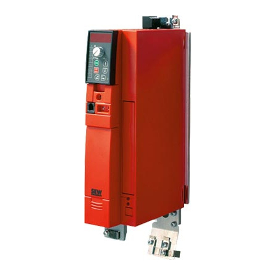
- Page 1 Edition ® MOVITRAC 02/2003 System Manual 1056 2915 / EN...
- Page 2 SEW-EURODRIVE...
-
Page 3: Table Of Contents
Contents Important Notes....................7 System Description................... 9 Technical Data....................15 P6.. Parameters....................... 65 P60. P600 Project Planning....................84 Safety Notes ....................121 Unit Design ....................122 Installation..................... 128 Startup......................139 Operation and Service.................. 158 Change Index....................164 Index....................... 165 System Manual –... - Page 4 Contents 1 Important Notes....................7 2 System Description................... 9 Overview of the system................9 The units at a glance................12 Functions / features ................13 3 Technical Data ....................15 CE-marking, UL approval and C-Tick ............. 15 General technical data ................16 Technical data of MOVITRAC®...
- Page 5 Contents 9 Startup......................139 General startup instructions ..............139 Preliminary work and resources............139 Integrated operating panel ..............140 Principles of operation with the integrated operating panel ....141 Manual speed control module and external setpoint selection ..... 143 Startup with the integrated operating panel .......... 146 Starting the motor .................
- Page 6 Contents System Manual – MOVITRAC® 07...
-
Page 7: Important Notes
Important Notes Important Notes Safety and warn- Always follow the safety and warning instructions contained in this publication! ing instructions Electrical hazard Possible consequences: Severe or fatal injuries. Hazard Possible consequences: Severe or fatal injuries. Hazardous situation Possible consequences: Slight or minor injuries. Harmful situation Possible consequences: Damage to the unit and the environment. - Page 8 Important Notes ® MOVITRAC 07 frequency inverters are units intended for stationary installation in switch cabinets. All instructions referring to the technical data and the permissible con- ditions where the unit is operated must be followed. Do not start up the unit (take it into operation in the designated fashion) until: •...
-
Page 9: System Description
System Description Overview of the system System Description Overview of the system 03065EXX ® Figure 1: MOVITRAC 07 system overview ® MOVITOOLS software ND line choke LOGODrive programming interface NF line filter UWS21A interface adapter BW braking resistor Gateways for HD output choke •... - Page 10 System Description Overview of the system Overview of properties Compact The unit has a very compact structure • Integrated brake chopper • Integrated EMC line filter: – Class B: 1-phase connection – Class A: 3-phase connection – 230 V: 0.37 ... 7.5 kW –...
- Page 11 System Description Overview of the system Extended func- 230 V units from 3.7 kW onwards and 500 V units from 5.5 kW onwards offer an extend- tions: ed range of functions including: • Flying restart circuit • Hoisting function • Setpoint stop function •...
-
Page 12: The Units At A Glance
System Description The units at a glance The units at a glance ® Mains connec- Motor power Continuous out- Inte- MOVITRAC 07 type Size tion put current grated 100 % / 125 % line filter class 0.37 kW / 0.5 HP 2.5 / 3.1 A MC07A004-2B1-4-00 0.55 kW / 0.75 HP... -
Page 13: Functions / Features
System Description Functions / features Functions / features ® MOVITRAC 07 frequency inverters are characterized by the following attributes: Unit properties • Wide voltage range: – 230 V units 1-phase and 3-phase for the voltage range 200 ... 240 V , 50/60 Hz –... - Page 14 System Description Functions / features • Protective features to protect against – Overcurrent – Ground fault – Overload – Overtemperature of the inverter – Overtemperature of the motor • Speed monitoring and monitoring of the motor and regenerative limit power. •...
-
Page 15: Technical Data
Technical Data CE-marking, UL approval and C-Tick Technical Data CE-marking, UL approval and C-Tick CE-marking ® Low Voltage Direc- MOVITRAC 07 frequency inverters comply with the regulations of the Low Voltage Di- tive rective 73/23/EEC. ® Electromagnetic MOVITRAC 07 frequency inverters are components of machines and systems. They compatibility EMC comply with the EMC product standard EN 61800-3 Variable-speed electrical drives . -
Page 16: General Technical Data
Technical Data General technical data General technical data ® The following technical data applies to all MOVITRAC 07 frequency inverters, regard- less of size. ® MOVITRAC All sizes Interference immunity To EN 61800-3 Interference emission with To limit value class EMC-compliant installation •... -
Page 17: Technical Data Of Movitrac® 07
Technical Data Technical data of MOVITRAC® 07 ® Technical data of MOVITRAC 230 V 51115AXX ® Figure 2: MOVITRAC 07 230 V units Size Power [kW / HP] 0.37 / 0.5 1.1 / 1.5 5.5 / 7.5 11 / 15 22 / 30 0.55 / 0.75 1.5 / 2.0... - Page 18 Technical Data Technical data of MOVITRAC® 07 230 V / 1-phase / size 0S / 0.37 ... 0.75 kW / 0.5 ... 1.0 HP 51105AXX ® Figure 4: MOVITRAC 07 / size 0S / 1-phase 230 V ® MOVITRAC MC07A (1-phase supply system) 004-2B1-4-..
- Page 19 Technical Data Technical data of MOVITRAC® 07 ® MOVITRAC MC07A (1-phase supply system) 004-2B1-4-.. 005-2B1-4-.. 008-2B1-4-.. GENERAL Power loss at I 45 W 55 W 65 W Current limitation 125 % I continuous duty (fan/pump operation) 150 % I for maximum 60 seconds PWM frequency 4 / 8 / 12 / 16 kHz Speed range...
- Page 20 Technical Data Technical data of MOVITRAC® 07 230 V / 1-phase / size 0L / 1.1 ... 2.2 kW / 1.5 ... 3.0 HP ® Figure 6: MOVITRAC 07 / size 0L / 1-phase 230 V ® MOVITRAC MC07A (1-phase supply system) 011-2B1-4-..
- Page 21 Technical Data Technical data of MOVITRAC® 07 ® MOVITRAC MC07A (1-phase supply system) 011-2B1-4-.. 015-2B1-4-.. 022-2B1-4-.. GENERAL Power loss at I 75 W 100 W 125 W Current limitation 125 % I continuous duty (fan/pump operation) 150 % I for maximum 60 seconds PWM frequency 4 / 8 / 12 / 16 kHz Speed range...
- Page 22 Technical Data Technical data of MOVITRAC® 07 230 V / 3-phase / size 0S / 0.37 ... 0.75 kW / 0.5 ... 1.0 HP 51105AXX ® Figure 8: MOVITRAC 07 / size 0S / 3-phase 230 V ® MOVITRAC 07A (3-phase supply system) 004-2A3-4-..
- Page 23 Technical Data Technical data of MOVITRAC® 07 ® MOVITRAC 07A (3-phase supply system) 004-2A3-4-.. 005-2A3-4-.. 008-2A3-4-.. GENERAL Power loss at I 45 W 55 W 65 W Current limitation 125 % I continuous duty (fan/pump operation) 150 % I for maximum 60 seconds PWM frequency 4 / 8 / 12 / 16 kHz Speed range...
- Page 24 Technical Data Technical data of MOVITRAC® 07 230 V / 3-phase / size 0L / 1.1 ... 2.2 kW / 1.5 ... 3.0 HP ® Figure 10: MOVITRAC 07 / size 0L / 3-phase 230 V ® MOVITRAC 07A (3-phase supply system) 011-2A3-4-..
- Page 25 Technical Data Technical data of MOVITRAC® 07 ® MOVITRAC 07A (3-phase supply system) 011-2A3-4-.. 015-2A3-4-.. 022-2A3-4-.. GENERAL Power loss at I 75 W 100 W 125 W Current limitation 125 % I continuous duty (fan/pump operation) 150 % I for maximum 60 seconds PWM frequency 4 / 8 / 12 / 16 kHz Speed range...
- Page 26 Technical Data Technical data of MOVITRAC® 07 230 V / 3-phase / size 1 / 3.7 kW / 5.0 HP ® Figure 12: MOVITRAC 07 / size 1 / 3-phase 230 V ® MOVITRAC 07A (3-phase supply system) 037-2A3-4-.. Part number 827 278 6 Part number with LOGODrive 827 285 9...
- Page 27 Technical Data Technical data of MOVITRAC® 07 ® MOVITRAC 07A (3-phase supply system) 037-2A3-4-.. GENERAL Power loss at I 210 W Current limitation 125 % I continuous duty (fan/pump operation) 150 % I for maximum 60 seconds PWM frequency 4 / 8 / 12 / 16 kHz Speed range 0 ...
- Page 28 Technical Data Technical data of MOVITRAC® 07 230 V / 3-phase / size 2 / 5.5 ... 7.5 kW / 7.5 ... 10 HP ® Figure 14: MOVITRAC 07 / size 2 / 3-phase 230 V ® MOVITRAC 07A (3-phase supply system) 055-2A3-4-..
- Page 29 Technical Data Technical data of MOVITRAC® 07 ® MOVITRAC 07A (3-phase supply system) 055-2A3-4-.. 075-2A3-4-.. GENERAL Power loss at I 300 W 380 W Current limitation 125 % I continuous duty (fan/pump operation) 150 % I for maximum 60 seconds PWM frequency 4 / 8 / 12 / 16 kHz Speed range...
- Page 30 Technical Data Technical data of MOVITRAC® 07 230 V / 3-phase / size 3 / 11 ... 15 kW / 15 ... 20 HP ® Figure 16: MOVITRAC 07 / size 3 / 3-phase 230 V ® MOVITRAC 07A (3-phase supply system) 110-203-4-..
- Page 31 Technical Data Technical data of MOVITRAC® 07 ® MOVITRAC 07A (3-phase supply system) 110-203-4-.. 150-203-4-.. GENERAL Power loss at I 580 W 720 W Current limitation 125 % I continuous duty (fan/pump operation) 150 % I for maximum 60 seconds PWM frequency 4 / 8 / 12 / 16 kHz Speed range...
- Page 32 Technical Data Technical data of MOVITRAC® 07 230 V / 3-phase / size 4 / 22 ... 30 kW / 30 ... 40 HP ® Figure 18: MOVITRAC 07 / size 4 / 3-phase 230 V ® MOVITRAC 07A (3-phase supply system) 220-203-4-..
- Page 33 Technical Data Technical data of MOVITRAC® 07 ® MOVITRAC 07A (3-phase supply system) 220-203-4-.. 300-203-4-.. GENERAL Power loss at I 1100 W 1300 W Current limitation 125 % I continuous duty (fan/pump operation) 150 % I for maximum 60 seconds PWM frequency 4 / 8 / 12 / 16 kHz Speed range...
- Page 34 Technical Data Technical data of MOVITRAC® 07 400/500 V / 3-phase / size 0M / 0.55 ... 1.1 kW / 0.75 ... 1.5 HP ® Figure 20: MOVITRAC 07 / size 0M / 3-phase 400/500 V ® MOVITRAC 07A (3-phase supply system) 005-5A3-4-..
- Page 35 Technical Data Technical data of MOVITRAC® 07 ® MOVITRAC 07A (3-phase supply system) 005-5A3-4-.. 008-5A3-4-.. 011-5A3-4-.. GENERAL Power loss at I 42 W 48 W 58 W Current limitation 125 % I continuous duty (fan/pump operation) 150 % I for maximum 60 seconds PWM frequency 4 / 8 / 12 / 16 kHz Speed range...
- Page 36 Technical Data Technical data of MOVITRAC® 07 400/500 V / 3-phase / size 0L / 1.5 ... 4.0 kW / 2.0 ... 5.0 HP ® Figure 22: MOVITRAC 07 / size 0L / 3-phase 400/500 V ® MOVITRAC 07A (3-phase supply system) 015-5A3-4- 022-5A3-4- 030-5A3-4-...
- Page 37 Technical Data Technical data of MOVITRAC® 07 ® MOVITRAC 07A (3-phase supply system) 015-5A3-4- 022-5A3-4- 030-5A3-4- 040-5A3-4- GENERAL Power loss at I 74 W 97 W 123 W 155 W Current limitation 125 % I continuous duty (fan/pump operation) 150 % I for maximum 60 seconds PWM frequency 4 / 8 / 12 / 16 kHz...
- Page 38 Technical Data Technical data of MOVITRAC® 07 400/500 V / 3-phase / size 2S / 5.5 ... 7.5 kW / 7.5 ... 10 HP ® Figure 24: MOVITRAC 07 / size 2S / 3-phase 400/500 V ® MOVITRAC 07A (3-phase supply system) 055-5A3-4-..
- Page 39 Technical Data Technical data of MOVITRAC® 07 ® MOVITRAC 07A (3-phase supply system) 055-5A3-4-.. 075-5A3-4-.. GENERAL Power loss at I 220 W 290 W Current limitation 125 % I continuous duty (fan/pump operation) 150 % I for maximum 60 seconds PWM frequency 4 / 8 / 12 / 16 kHz Speed range...
- Page 40 Technical Data Technical data of MOVITRAC® 07 400/500 V / 3-phase / size 2 / 11 kW / 15 HP ® Figure 26: MOVITRAC 07 / size 2 / 3-phase 400/500 V ® MOVITRAC 07A (3-phase supply system) 110-5A3-4-.. Part number 827 256 5 Part number with LOGODrive 827 301 4...
- Page 41 Technical Data Technical data of MOVITRAC® 07 ® MOVITRAC 07A (3-phase supply system) 110-5A3-4-.. GENERAL Power loss at I 400 W Current limitation 125 % I continuous duty (fan/pump operation) 150 % I for maximum 60 seconds PWM frequency 4 / 8 / 12 / 16 kHz Speed range 0 ...
- Page 42 Technical Data Technical data of MOVITRAC® 07 400/500 V / 3-phase / size 3 / 15 ... 30 kW / 20 ... 40 HP ® Figure 28: MOVITRAC 07 / size 3 / 3-phase 400/500 V ® MOVITRAC 07 (3-phase supply system) 150-503-4-..
- Page 43 Technical Data Technical data of MOVITRAC® 07 ® MOVITRAC 07 (3-phase supply system) 150-503-4-.. 220-503-4-.. 300-503-4-.. GENERAL Power loss at I 550 W 750 W 950 W Current limitation 125 % I continuous duty (fan/pump operation) 150 % I for maximum 60 seconds PWM frequency 4 / 8 / 12 / 16 kHz Speed range...
- Page 44 Technical Data Technical data of MOVITRAC® 07 ® MOVITRAC 07 sizes 0S, 0M, 0L for DIN rail mounting (optional accessory) 04329AXX ® Figure 30: MOVITRAC 07 dimensions for DIN rail mounting (optional accessory) ® MOVITRAC 230 V Dimensions A x B x C 90 x 185 x 150 mm 90 x 295 x 150 mm 3.5 x 7.2 x 5.9 in...
-
Page 45: Movitrac® 07 Electronics Data
Technical Data MOVITRAC® 07 electronics data ® MOVITRAC 07 electronics data Function Terminal Name Data Setpoint input (differential X10:13 AI11 (+) 0 ... +10 V (R > 200 kΩ) = 250 Ω) input) X10:14 AI12 (0) 0 ... 20 mA / 4 ... 20 mA (R Resolution 10 bit, sampling interval 1 ms Internal setpoints n11/n12/n13 and n21/n22/n23 = 0 ... -
Page 46: Interface Converter Uws21A
Technical Data Interface converter UWS21A Interface converter UWS21A UWS21A Part number: 823 077 3 The UWS21A option converts RS-232 signals (e.g. from a PC) into RS-485 signals. The ® signals are then sent to the RS-485 interface of MOVITRAC RS-232 Establish the connection between the UWS21A and the PC using a commercially avail- able shielded serial interface cable. -
Page 47: Movitools
Technical Data MOVITOOLS MOVITOOLS Part number: 918 505 4 The MOVITOOLS program package includes: • SHELL • SCOPE plus® • IPOS Compiler • LOGODrive With MOVITOOLS, you can address the following three series of units: ® • MOVIDRIVE MD_60A ® •... - Page 48 Technical Data MOVITOOLS LOGODrive The LOGODrive graphical programming interface is integrated in the MOVITOOLS soft- series of units ware from version 2.6 onwards. You can add and link function blocks into a sequential function chart using LOGODrive. System Manual – MOVITRAC® 07...
- Page 49 Technical Data MOVITOOLS ® SCOPE SCOPE for MOVITOOLS is an oscilloscope program for SEW inverters. You can opti- mize drives independently using SCOPE. The inverter records data such as its re- sponse functions to setpoint step changes in real time. You can transfer this information to the PC and display it there in graphical format.
-
Page 50: Movitrac® 07 For Din Rail Mounting
Technical Data MOVITRAC® 07 for DIN rail mounting ® MOVITRAC 07 for DIN rail mounting ® Hardware kits for DIN rail mounting of MOVITRAC 07 are available with the following part numbers: Type Part number Size FHS01 823 604 6 FHS03 824 037 X FHS02... -
Page 51: Fieldbus Interfaces
Technical Data Fieldbus interfaces Fieldbus interfaces Gateways are available for the following bus systems for connecting fieldbuses: • PROFIBUS UFP11A (part number: 823 896 0) • DeviceNet UFD11A (part number: 823 897 9) • INTERBUS UFI11A (part number: 823 898 7) •... -
Page 52: Bw Series Braking Resistors
Technical Data BW series braking resistors 3.10 BW series braking resistors ® General informa- BW series braking resistors are adapted to the MOVITRAC 07 series of inverters. The tion braking resistors are convection-cooled. The permitted ambient temperature range is - 20 °C ... - Page 53 Technical Data BW series braking resistors Install additional overload protection for the wire and grid resistors by means of a bime- tallic relay in the –R line (X3). Set the trip current to the value I in the following tables. Do not use any electronic or electromagnetic fuses since the brief excess currents which are still permitted may cause them to trip.
- Page 54 Technical Data BW series braking resistors 230 V Type BW027-006 BW027-012 BW018-015 BW018-035 BW018-075 BW012-025 BW012-050 BW012-100 Part number 822 422 6 822 423 4 821 684 3 821 685 1 821 686 X 821 680 0 821 681 9 821 682 7 100 % cdf 0.6 kW...
- Page 55 Technical Data BW series braking resistors Dimensions of BW braking resistors 05246AXX Figure 34: Dimensions of BW braking resistors, 1 flat-type / 2 grid resistor / 3wire resistor Flat-type resistors: The connecting lead is 500 mm (19.69 in) long. The scope of delivery includes four M4 threaded bushes, types 1 and 2.
- Page 56 Technical Data BW series braking resistors Dimensions of touch guard BS 05247AXX Figure 35: Dimensions, touch guard BS with grommet [1] and DIN rail mounting [2] Type Main dimensions [mm (in)] Fixing dimensions [mm (in)] Weight [kg (lb)] BS-003 60 (2.4) 160 (6.3) 146 (5.8) 125 (4.9)
-
Page 57: Series Hd Output Chokes
Technical Data Series HD output chokes 3.11 Series HD output chokes You can reduce the radiated interference of the unshielded motor cable by using an out- put choke. Output choke type HD001 HD002 HD003 Part number 813 325 5 813 557 6 813 558 4 Max. -
Page 58: 3.12 Nd Line Chokes
Technical Data ND line chokes 3.12 ND line chokes The line choke assists in overvoltage protection. The line choke restricts the charging current when several inverters are connected in parallel on the input side. Application: see Sec. "Project Planning". The ambient temperature range is -25 °C ... +45 °C. The enclosure is IP 00 (EN60529). - Page 59 Technical Data ND line chokes Dimensions ND 010-301 / ND 020-151 05249AXX Figure 37: Dimensions ND 010-301 / ND 020-151 Type Main dimensions [mm (in)] Fixing dimensions [mm (in)] Weight [kg (lb)] ND 010-301 90 (3.5) 100 (3.9) 80 (3.2) 70 (2.8) 64 (2.5) 52 (2.1)
- Page 60 Technical Data ND line chokes Dimensions ND 020-013 / ND 027-123 / ND 035-073 / ND 085-013 / ND 1503 05250AXX Figure 38: Dimensions ND 020-013 / ND 027-123 / ND 035-073 / ND 085-013 / ND 1503 with [1] space for modular terminal blocks with touch guard Type Main dimensions [mm (in)]...
-
Page 61: Nf Line Filters
Technical Data NF line filters 3.13 NF line filters The line filter suppresses interference emissions on the line side of inverters. The am- bient temperature range is -25 °C ... +45 °C. The enclosure is IP20 (EN 60529). Type NF009 NF014 NF018 NF035... - Page 62 Technical Data NF line filters 05264AXX Figure 39: Dimensions, line filter Line filter Hole dimen- Main dimensions Fixing dimensions PE connec- Weight type sion tion kg (lb) NF009 195 (7.7) 180 (7.1) 0.8 (1.8) 55 (2.2) NF014 225 (8.9) 80 (3.2) 20 (0.8) 210 (8.3) 0.9 (2.0)
-
Page 63: Hf Output Filter
Technical Data HF output filter 3.14 HF output filter SEW HF output filters are sine filters. Sine filters smooth the output voltage of inverters. Use output filters in the following circumstances: • In group drives (several motor feeders in parallel); the discharge currents in the mo- tor cables are suppressed •... - Page 64 Technical Data HF output filter 05251AXX Figure 40: Dimensions HF...-503 Type Main dimensions Fixing dimensions Hole Ventilation clearance dimension Bottom HF008/015/022/030-503 80 (3.2) 286 (11.3) 176 (6.9) – 265 (10.4) 7 (0.28) 100 (3.9) 100 (3.9) HF040/055/075-503 135 (5.3) 296 (11.7) 216 (8.5) 70 (2.8) 283 (11.1)
-
Page 65: Parameters
P6.. Parameters P60. Explanation of the parameters P600 Parameters As a rule, you only set the parameters during startup and if servicing is required. You ® can set the MOVITRAC 07 parameters in various ways: • Using the integrated operating panel •... - Page 66 P6.. Parameters P60. Explanation of the parameters P600 OP Name Description Display values This group of parameters contains information about • Process values • Statuses • Fault memory the unit Process values Speed (signed) [rpm] Resolution 1 rpm. The displayed speed is the calculated actual speed. Frequency (signed) [Hz] Output frequency of the inverter.
- Page 67 P6.. Parameters P60. Explanation of the parameters P600 OP Name Description Unit data Unit type Displays the unit type, e.g. MC07A008-2B1 Output rated current [A] Displays the rated unit current in [A] Firmware basic unit Part number and version of the firmware Fault memory •...
- Page 68 P6.. Parameters P60. Explanation of the parameters P600 OP Name Description • Setpoint source 1 / UNIPOL/FIX.SETPT The setpoint is provided by the analog inputs or the fixed setpoints. The unit processes the fixed setpoints according to their value. The binary inputs specify the direction of rotation.
- Page 69 P6.. Parameters P60. Explanation of the parameters P600 OP Name Description Control signal source 3-WIRE-CONTROL X10:2 = CW/STOP X10:3 = CCW/STOP X10:4 = Enable/Rapid stop X10:13/14 = Set- point input AI = Output fre- quency = Start/stop fre- quency CW = Turning to the right CCW = Turning to the left...
- Page 70 P6.. Parameters P60. Explanation of the parameters P600 OP Name Description • AI1 operation mode 0 / 3000 rpm (0 – 10 V) Voltage input with reference 3000 rpm (0 ... 10 V = 0 ... 3000 rpm). You can adapt the characteristic curve with AI1 scaling . Switch S11 = V 1 / N-MAX (0 –...
- Page 71 P6.. Parameters P60. Explanation of the parameters P600 OP Name Description Motor potentiometer function (see P100 Setpoint source ) • Ramp t3 (motor potentiome- Setting range 0.2 ... 20 ... 50 [s] ter) The ramp takes effect when the Motor pot. up and Motor pot. down terminal functions are used.
- Page 72 P6.. Parameters P60. Explanation of the parameters P600 OP Name Description Controller parameters PI-controller (see Sec. Project Planning / PI-controller for explanations of the parameters) • PI-controller 0 / OFF PI-controller switched off. 1 / NORMAL PI-controller switched on normally. 2 / INVERTED PI-controller switched on inverted.
- Page 73 P6.. Parameters P60. Explanation of the parameters P600 OP Name Description Motor adjustment The P320 Automatic adjustment function is only of significance for single motor operation. You can use this function for all motors and control modes. The inverter automatically sets P322 IxR compensation and P321 Boost with each enable operation and saves the values.
- Page 74 P6.. Parameters P60. Explanation of the parameters P600 OP Name Description Reference signals The following reference values are used for recording and signaling certain operational states. All signals in parameter group 4__ can be output via binary outputs. The signals are valid if the inverter has signaled ready after switch-on and there is no fault display. Speed reference signal The inverter outputs the "1"...
- Page 75 P6.. Parameters P60. Explanation of the parameters P600 OP Name Description Monitoring functions Speed monitoring The drive only attains the speed required by the setpoint if it has sufficient torque. If the inverter reaches P303 Current limit , this is because it did not attain the required speed. Speed monitoring is triggered if the inverter exceeds the current limit for longer than set in P501 Delay time .
- Page 76 P6.. Parameters P60. Explanation of the parameters P600 OP Name Description Binary outputs Effect of 0 signal 1 signal NO FUNCTION: - /FAULT: Collective fault signal READY: Not ready Ready OUTP. STAGE ON: Unit inhibited Unit enabled and motor is energized ROT.
- Page 77 P6.. Parameters P60. Explanation of the parameters P600 OP Name Description VFC & DC BRAK. / V/f & DC BRAKING: With DC braking, the asynchronous motor brakes by means of a current injec- tion. In this case, the motor brakes without a braking resistor on the inverter. The following figure shows the braking torque profile when the braking current is the same as the motor rated current.
- Page 78 P6.. Parameters P60. Explanation of the parameters P600 OP Name Description Operating mode (setting also 0 / VFC (field-oriented voltage flux control mode) or on the operating panel with VFC & HOIST (field-oriented control mode for hoist applications, can , P-01) only be set in MOVITOOLS) 3 / VFC &...
- Page 79 P6.. Parameters P60. Explanation of the parameters P600 OP Name Description Brake function • Brake application time Setting range 0 ... 0.1 ... 2 [s] The parameter applies both to the brake release time and the brake reaction The start and stop speeds time.
- Page 80 P6.. Parameters P60. Explanation of the parameters P600 OP Name Description • Factory setting yes / YES (perform factory setting) no / NO (do not perform factory setting) - / (Delivery condition) Setting P803 Parameter lock = ON enables you to prevent any changes to parameters. This does not apply to P840 ®...
- Page 81 P6.. Parameters P60. Explanation of the parameters P600 OP Name Description • SBus timeout delay Setting range 0 ... 650 [s] P815 sets the monitoring time for data transmission via the system bus. ® MOVITRAC 07 performs the fault response RAPID STOP/FAULT if there is no data traffic via the system bus for the period set in P815.
- Page 82 P6.. Parameters P60. Explanation of the parameters P600 OP Name Description Reset response Manual reset ® Parameter P840 corre- MOVITRAC 07 resets the existing fault. P840 automatically reverts to sponds to the STOP/RESET NO following a reset. The motor immediately restarts to the specified key.
- Page 83 P6.. Parameters P60. Explanation of the parameters P600 OP Name Description ® Fieldbus parameter settings (refer to the MOVITRAC 07 Communication manual for more information) P870 ... P872 can be used for defining the contents of process output data words PO1 ... PO3. This definition is neces- ®...
-
Page 84: Project Planning
< 1.5 x M • Required motor speed < n • Thermal load with regard for the setting range and cyclic duration factor ↓ ® Selection of the MOVITRAC 07 frequency inverter • Motor/inverter assignment • Continuous power, peak power •... -
Page 85: Options For Standard Applications
Project Planning Options for standard applications Options for standard applications Refer to the following table for information about the options for straightforward applica- tions. Conditions for straightforward applications are: • Braking time is less than 25 % of cyclic duration factor cdf •... -
Page 86: Description Of Applications
Project Planning Description of applications Description of applications ® Inverter selection For MOVITRAC 07, there are two applications relevant for project planning. 100 % rated cur- These are applications with constant load, for example: rent • Conveyor drives • Trolleys •... - Page 87 Project Planning Description of applications 05119AXX = Recommended voltage/speed characteristic curve and resultant torque characteristic = Torque reserve range With hoists, select the motor power in accordance with the load type: • S1 (100 % cdf.): Select the motor power 1 level higher than the selected inverter pow- er, e.g.
-
Page 88: Speed-Torque Characteristic
Project Planning Speed-torque characteristic Speed-torque characteristic n = 1400 rpm (50 Hz) n = 1680 rpm (60 Hz) n [rpm] 0 100 1000 1800 2200 2600 1400 2900 » 50 Hz » 100 Hz n [rpm] 0 120 1200 1680 2160 2640 3120... - Page 89 Project Planning Motor selection Voltage/fre- The asynchronous motor follows a load-dependent voltage/frequency characteristic in quency charac- V/f operating mode. The motor gets the full motor torque even at the slowest speeds. teristic This is because the motor model is continuously calculated in VFC mode. Set the char- acteristic curve during startup with rated motor voltage and rated motor frequency.
- Page 90 Project Planning Motor selection Inverter/motor The following table shows the possible inverter/motor combinations. It is also possible combinations to assign motors 1 frame size different to the inverters. The 4-pole motors (1500 rpm) ® are stored in the factory settings of MOVITRAC 07.
-
Page 91: Overload Capacity
Project Planning Overload capacity Overload capacity ® MOVITRAC 07 frequency inverters permanently calculate the load on the inverter out- put stage (unit utilization). They can output the maximum possible power in any operat- ing status. The permitted continuous output current depends on the ambient tempera- ture, heat sink temperature, supply voltage and PWM frequency. -
Page 92: Load Capacity Of The Units At Low Output Frequencies
Project Planning Load capacity of the units at low output frequencies Load capacity of the units at low output frequencies ® The thermal model in MOVITRAC 07 implements dynamic limiting of the maximum out- put current. Consequently, the thermal model only permits less than 100 % output cur- rent at output frequencies less than 2 Hz if the capacity utilization is high. -
Page 93: Selection Of The Braking Resistor
Project Planning Selection of the braking resistor Selection of the braking resistor • High voltage The connection leads to the braking resistor carry a high DC voltage (ca. 900 V). Select the braking resistor cables with regard to this high DC voltage. •... - Page 94 Project Planning Selection of the braking resistor Flat-type 230 V 05812AXX Figure 47: Flat-type 230 V P = Intermittent power [kW] cdf = Cyclic duration factor of the braking resistor [%] 100 % cdf = Continuous power [kW] Wire resistor 230 V 05813AXX Figure 48: Wire resistor 230 V P = Intermittent power [kW]...
- Page 95 Project Planning Selection of the braking resistor Example When an intermittent braking power of 7 kW is needed with a cyclic duration factor of 30 %, this requires a braking resistor with a continuous power of 2 kW, for example BW247. Braking resistor type BW039-003 BW039-006...
- Page 96 Project Planning Selection of the braking resistor Example When an intermittent braking power of 3 kW is needed with a cyclic duration factor of 40 %, this requires a braking resistor with a continuous power of 1.5 kW, for example BW018-015.
- Page 97 Project Planning Selection of the braking resistor Wire resistor 400/500 V 05815AXX Figure 51: Wire resistor 400/500 V P = Intermittent power [kW] cdf = Cyclic duration factor of the braking resistor [%] 100 % cdf = Continuous power [kW] Example For an intermittent braking power of 7 kW with a cyclic duration factor of 30%, you will have to use a braking resistor with a continuous power of 2 kW, such as the BW247.
- Page 98 Project Planning Selection of the braking resistor Grid resistor 400/500 V 05816AXX Figure 52: Grid resistor 400/500 V Example For an intermittent braking power of 3 kW with a cyclic duration factor of 40 %, you will have to use a braking resistor with a continuous power of 1.5 kW, such as BW018-015. Braking resistor type BW039-012 BW039-026...
-
Page 99: Brake Connection
Project Planning Brake connection Brake connection For detailed information about the SEW brake system, refer to Geared Motors catalog • • Drive Engineering – Practical Implementation, Vol. 4 manual SEW brake systems are DC operated disc brakes which are released electromagneti- cally and applied by spring force. - Page 100 Project Planning Supply system lead and motor cable When several single-phase devices are used, the size of the shared neutral conductor must always be selected for the total current. Select with reference to the total current even if the unit connections are distributed over the three mains phases. This is because the 3rd supply system harmonic is always cumulative.
- Page 101 Project Planning Supply system lead and motor cable Motor feeder The maximum motor feeder length is dependent on: length • cable type, • voltage drop in the cable, • set PWM frequency. • Use of an output filter (not permitted with 230 V units) ®...
- Page 102 Project Planning Supply system lead and motor cable Voltage drop Select the line cross section of the motor lead so the voltage drop is as small as pos- sible. An excessively high voltage drop means that the motor does not achieve its full torque.
-
Page 103: Group Drive
Project Planning Group drive 5.12 Group drive In V/f character. operating mode, a group of asynchronous motors can be operated on one inverter. Please note: • Select V/f operating mode • Set the power of the largest motor • Switch off automatic adjustment P320 •... -
Page 104: Line Chokes
Project Planning Line chokes Output filter Usually, there is no need for an output filter with small groups of two to three motors. An output filter HF... is required if the maximum motor lead length (l ) given in the table is not adequate. - Page 105 Project Planning Line chokes For connecting Prerequisites for connecting several single-phase inverters to one three-phase line several single- choke are: phase inverters • The supply system contactor must be designed for the total current. to one three- • The fuse must correspond to the rated current value of the line choke. phase line choke ®...
-
Page 106: Installation Notes
Project Planning Installation notes ® Example: Nine sin- Nine MOVITRAC 07 MC07A-008-2B1-00 units (0.75 kW) are to be connected to one gle-phase inverters three-phase line choke. The rated current of the inverters is 9.9 A. on one three- Make sure the line cross section corresponds to the selected fuse. In addition, you must phase line choke configure the neutral conductor in accordance with the total current. - Page 107 Project Planning Installation notes ® Interference immu- With regard to interference immunity, MOVITRAC 07 meets all the requirements stip- nity ulated in EN 50082-2 and EN 61800-3. Interference emis- Higher levels of interference are permitted in industries. In industrial environments, it sion may be possible to dispense with the measures listed below depending on the situation of the supply system and the machine configuration.
- Page 108 Project Planning Installation notes Block diagram for [1]: Alternative 1 with HD output chokes installation [2]: Alternative 2 with shielded motor lead according to the class B limit 05129BXX Figure 55: Installation according to class B limit Please refer to the publication "Drive Engineering – Practical Implementation, Electro- magnetic Compatibility (EMC) in Drive Engineering"...
-
Page 109: 5.15 Connecting The Optional Power Components
Project Planning Connecting the optional power components 5.15 Connecting the optional power components Series ND... line chokes 05259AXX Figure 56: Connecting ND... line chokes Series NF...-... line filters 05260AXX Figure 57: Connecting NF...-... line filters Series HD... out- put chokes Output choke type HD001 HD002... -
Page 110: Electronics Cables And Signal Generation
Project Planning Electronics cables and signal generation • Several motors can be connected jointly to one output filter when multiple motors are operated on one inverter. The total value of the rated motor currents must not exceed the rated throughput current of the output filter. •... -
Page 111: 5.17 Pi-Controller
Project Planning PI-controller 5.17 PI-controller You can use the implemented PI-controller for temperature control, pressure control or other applications. The PI-controller can be switched on and off. 03178BEN Figure 59: Structural diagram showing the implementation of the PI-controller Connect the actual value from the sensor (temperature, pressure, etc.) to analog input AI1. - Page 112 Project Planning PI-controller Setting parame- ters Activating the PI- Switch the PI-controller off and on using parameter P250. The setpoint and actual value controller settings mentioned initially are active when you switch on the PI-controller. The NORMAL setting increases the correcting variable if there is a positive system de- viation;...
- Page 113 Project Planning PI-controller Actual value Unipolar input AI1 is the actual value input. acquisition You can acquire the actual value as follows using P253 PI actual value mode : • 0 ... 10 V: The following applies to operation as a voltage input: 0 ...
-
Page 114: Application Examples
Project Planning Application examples Inverter control You can determine the direction of rotation using direction of rotation terminals "CW/STOP" and "CCW/STOP". After the enable, the inverter increases the speed using speed ramp P130 until minimum speed P301 is reached. PI control takes effect once the minimum speed has been reached. - Page 115 Project Planning Application examples Without dropping The resistance value of the external setpoint potentiometer R1 must be approx. 47 kΩ. resistor You are not allowed to connect a TF if the external setpoint potentiometer does not have a dropping resistor. 05324AXX Figure 61: External setpoint potentiometer with DI01 = CW/STOP / DI02 = CCW/STOP / DI03 = Enable / DO02 = Brake...
- Page 116 Project Planning Application examples Positioning of a trolley Principle Positioning of a trolley with rapid traverse and crawl speed, position detection using proximity sensors. You must guarantee the emergency off function using a separate safety circuit. Install a braking resistor. Perform startup for VFC mode.
- Page 117 Project Planning Application examples Terminals Rapid traverse: DI04 = 1 and DI05 = 1 Crawl speed: DI04 = 1 and DI05 = 0 03411CXX Figure 62: Wiring of electronics terminal strip with DI01 = CW/STOP/ DI02 = CCW/STOP / DI03 = Enable / DO01-C and DO01-NO = "Fault"...
- Page 118 Project Planning Application examples Pressure control Principle In this application, the inverter controls the water pressure in a piping system. The PI- ® controller implemented in MOVITRAC 07 is used for this. P163 "n11 PI-controller inter- nal setpoint" specifies the pressure setpoint. STO P RESET System Manual –...
- Page 119 Project Planning Application examples Connection Two indicator lamps, "Fault" and "Pressure reached" Motor temperature monitored by TF 03420CXX Figure 63: Pressure control connection with DI01 = CCW/STOP / DI02 = Enable / DI04 = Fault reset / DI05 = TF fault / DO01-C and DO01- NO = "Fault"...
- Page 120 Project Planning Application examples Parameters The following parameters are relevant for the aforementioned application. Check wheth- er you can adopt the factory setting values without changes. P163 n11 PI-controller internal setpoint P450 PI actual value reference P250 PI controller P451 Signal = "1" if: PI actual value / PI refer- ence P251 P-gain speed controller P601 Binary input DI02: Enable...
-
Page 121: Safety Notes
Safety Notes Application examples Safety Notes Installation and • Never install damaged products or take them into operation. Please submit a startup complaint to the transport company immediately in the event of damage. • Installation, startup and service work on the unit only by trained personnel. The personnel must be trained in the relevant aspects of accident prevention and must comply with the regulations in force (e.g. -
Page 122: Unit Design
Unit Structure Unit design Unit Structure Unit design Size 0S, 0M, 0L 02978BXX ® Figure 65: MOVITRAC 07 unit structure, sizes 0S, 0M, 0L 1. X1: Mains connection 3-phase: L1 / L2 / L3 / PE or 1-phase: L/N/PE 2. Operating panel 3. - Page 123 Unit Structure Unit design Size 1, 2S, 2 05132AXX ® Figure 66: MOVITRAC 07 unit structure, sizes 1, 2S, 2 1. X1: Mains connection 3-phase: L1 / L2 / L3 / PE screw 2. Operating panel 3. DIP switch S11 changeover U-signal / I-signal 4.
- Page 124 Unit Structure Unit design Size 3 05295AXX ® Figure 67: MOVITRAC 07 unit structure, size 3 1. PE connections 2. X1: Mains connection 3-phase: L1 (1) / L2 (2) / L3 (3) 3. X4: DC link circuit connection (not used) 4.
- Page 125 Unit Structure Unit design Size 4 05296AXX ® Figure 68: MOVITRAC 07 unit structure, size 4 1. X2: PE connection 2. X1: Mains connection 3-phase: L1 (1) / L2 (2) / L3 (3) 3. X4: DC link circuit connection (not used) 4.
-
Page 126: Unit Designation And Scope Of Delivery
Unit Structure Unit designation and scope of delivery Unit designation and scope of delivery Sample unit designation Type MC Series and generation Version A Recommended motor 022 = 2.2 kW power 2 = 200 ... 240 V Connection voltage 5 = 380 ... 500 V B = Radio interference suppres- sion B Radio interference sup-... - Page 127 Unit Structure Unit designation and scope of delivery Scope of delivery loose items 03000AXX Figure 70: Scope of delivery, included loose size 0 Scope of delivery, included loose for size • Shield clamps for electronics cables (2 clamps with one screw each) [1] •...
-
Page 128: Installation
Installation Installation instructions Installation Installation instructions It is essential to comply with the safety notes during installation! Tightening • Only use genuine connection elements. Note the permitted tightening torques ® torques of MOVITRAC 07 power terminals. → – Size 0S/M/L 0.5 Nm (4.4 lb.in) →... - Page 129 Installation Installation instructions Line choke • When more than four 3-phase units or more than one 1-phase unit are connect- ed to a supply system contactor designed for the total current: Insert a line choke in the circuit to limit the inrush current. Separate cable •...
- Page 130 Installation Installation instructions ® Line filter MOVITRAC 07 frequency inverters are equipped with an line filter as standard. They comply with the following limit value class to EN 55011 on the line side without further measures: • B: 1-phase connection •...
- Page 131 Installation Installation instructions ® HD output choke • Install the output choke close to MOVITRAC 07 beyond the minimum clearance. • Always route all three phases (not the PE!) together through the output choke. • If the cable is shielded, the shield is not allowed to be routed through the output choke.
-
Page 132: Ul Compliant Installation
Installation UL compliant installation UL compliant installation Please note the following points for UL compliant installation: • Only use copper cables with the following temperature ranges as connection leads: ® – For MOVITRAC 07 ... Temperature range 60/75 °C. ® •... -
Page 133: Power Shield Clamp
Installation Power shield clamp Power shield clamp ® For sizes 1 / 2S SEW-EURODRIVE supplies a power shield clamp as standard with MOVITRAC size 1 / 2S. Install this power shield clamp together with the retaining screws of the unit. 02012BXX ®... -
Page 134: Touch Guard
Installation Touch guard For size 2 SEW-EURODRIVE supplies a power shield clamp with two retaining screws as stan- ® dard with MOVITRAC 07 size 2. Install this power shield clamp together with the two retaining screws on X6. 01469BXX ® Figure 75: Power shield clamp for MOVITRAC 07 size 2 1. -
Page 135: Wiring Diagram 230 V 0.37
Installation Wiring diagram 230 V 0.37 ... 2.2 kW / 400 V 0.55 ... 4.0 kW Wiring diagram 230 V 0.37 ... 2.2 kW / 400 V 0.55 ... 4.0 kW 3 x 230 V / PE 1 x 230 V / N / PE 3 x 400/500 V / PE... -
Page 136: Wiring Diagram 230 V 3.7
Installation Wiring diagram 230 V 3.7 ... 30 kW / 400 V 5.5 ... 30 kW Wiring diagram 230 V 3.7 ... 30 kW / 400 V 5.5 ... 30 kW 3 x 230 V / PE 3 x 400/500 V / PE F11/F12/F13 (AC-3) - Page 137 Installation Wiring diagram 230 V 3.7 ... 30 kW / 400 V 5.5 ... 30 kW Connection of the brake rectifier A separate supply system lead is required for connecting the brake rectifier; sup- ply from the motor voltage is not permitted! Only use contactors in utilization category AC-3 (IEC 158-1) for K11 and K12.
-
Page 138: System Bus (Sbus) Installation
SC21 = System bus high SC12 = System bus low SC11 = System bus high = System bus terminating resistor SBus MOVITRAC 07: Connect the terminating equipment to SC11/SC12. SC21/SC22 are only active when S12 = OFF. System Manual – MOVITRAC® 07... -
Page 139: Startup
Startup General startup instructions Startup Using the IN/OUT key : Press the key once to go further down into the menu struc- ture (selecting functions). Press twice or use one long key press to change to higher lev- els in the menu structure. General startup instructions It is essential to adhere to the safety notes during startup! Prerequisite... -
Page 140: Integrated Operating Panel
Startup Integrated operating panel Integrated operating panel Operation The following basic principle applies: Press the key once to start editing. Double- click the key to exit edit mode. Functions of the The UP, DOWN and IN/OUT buttons are used for navigating through the menus. The operating panel RUN and STOP/RESET buttons are used for controlling the drive. -
Page 141: Principles Of Operation With The Integrated Operating Panel
Startup Principles of operation with the integrated operating panel Principles of operation with the integrated operating panel n11 n12 n [rpm] [rpm] [s/rpm] P081 [F-00 ... F-99] <-2x 1x-> <-2x 1x-> P100 ... P861 [ms/%/...] <-2x 1x-> P-01 ... P-05 [kW/Hz/...] <-2x 1x->... - Page 142 Startup Principles of operation with the integrated operating panel Available sym- You can select the following symbols using keys bols Symbol Function Displays the inverter status or (in "drive enabled" status) the calculated actual speed in [rpm] Displays the apparent output current in [A] Sets the accelerating ramp in [s] Sets the deceleration ramp in [s] Sets the maximum speed in [rpm]...
-
Page 143: Manual Speed Control Module And External Setpoint Selection
Startup Manual speed control module and external setpoint selection Fault indication If a fault occurs, the display changes to the symbol and it shows the flashing fault code, e.g. F-11 (fault list in Sec. Operation and servicing). Warnings Some parameters are not allowed to be altered in all operating states. If you try to do so, the following display appears: r-19 ... - Page 144 Startup Manual speed control module and external setpoint selection You can limit the speed by P301 Minimum speed and P302 Maximum speed . After a fault, a reset can be performed using the "STOP/RESET" button, the terminal or the interface. "Manual speed control module" operating mode is once again active after the reset.
- Page 145 Startup Manual speed control module and external setpoint selection Enable direction of The direction of rotation is determined by the setpoint if you set P101 Control signal rotation with RS- source and P100 Setpoint source to RS485 or SBus (RS485 only for service purposes). 485 or SBus You must enable the setpoint via SBus or RS-485 using the "CW/STOP"...
-
Page 146: Startup With The Integrated Operating Panel
Startup Startup with the integrated operating panel Startup with the integrated operating panel 02975GXX Figure 82: Startup with the integrated operating panel (2x = double-click / * = factory setting) P-01 = Operating mode P-03 = Rated motor speed P-05 = Rated motor voltage P-02 = Rated motor power P-04 = Rated motor frequency System Manual –... - Page 147 Startup Startup with the integrated operating panel General informa- If you are not connecting the motor indicated in the motor selection table: Enter param- tion eters P-01 to P-05 correctly according to the nameplate (access via Name Range / factory setting P-01 Operating mode VFC or VFC &...
-
Page 148: Starting The Motor
Startup Starting the motor Starting the motor Analog setpoints The following table shows which signals must be present on terminals X10:2 ... X10:4 (DIØ1 ... DIØ5) when the "UNIPOL/FIX.SETPT" setpoint is selected (P100), in order to operate the drive with analog setpoints. Terminal X10:13/14 X10:2... -
Page 149: Loading A Logodrive Program
Startup Loading a LOGODrive program Loading a LOGODrive program • Start MOVITOOLS Manager. ® • Connect the MOVITRAC 07 to a vacant serial port on your PC using the UWS21A interface converter. Select this interface in the PC Interface group. ®... -
Page 150: Parameter List
Startup Parameter list Parameter list All parameters which can also be displayed and edited using the symbol on the op- erating panel have a • in the "OP" (operating panel) column. If more than one value can be selected, the factory setting is highlighted in bold. OP Index Name Range / factory setting... - Page 151 Startup Parameter list OP Index Name Range / factory setting Value after startup dec. Display MOVITOOLS Binary outputs Binary output /FAULT (factory setting) DO01 Binary output BRAKE RELEASED (factory setting) DO02 Binary outputs Binary display DO01, DO02 Unit data Unit type [Text] Output rated cur- rent...
- Page 152 Startup Parameter list OP Index Name Range / factory setting Value after startup dec. Display MOVITOOLS Analog input 1 (+10 V) • 8463 AI1 scaling 0.1 ... 1 ... 10 • 8465 AI1 operation 3000 rpm (0 – 10 V) mode N-MAX (0 –...
- Page 153 Startup Parameter list OP Index Name Range / factory setting Value after startup dec. Display MOVITOOLS Fixed setpoints (set 2) • 8492 Internal setpoint 0 ... 150 ... 5000 [rpm] • 8493 Internal setpoint 0 ... 750 ... 5000 [rpm] •...
- Page 154 Startup Parameter list OP Index Name Range / factory setting Value after startup dec. Display MOVITOOLS Reference signals Speed reference signal • 8539 Speed reference 0 ... 750 ... 5000 [rpm] value • 8540 Hysteresis 0 ... 100 ... +500 [rpm] •...
- Page 155 Startup Parameter list OP Index Name Range / factory setting Value after startup dec. Display MOVITOOLS Binary outputs • 8804 Binary outputs DO01 DO02 /FAULT BRAKE RELEASED READY BRAKE RELEASED SPEED REFERENCE BRAKE RELEASED SP/ACT.VAL.COMP. BRAKE RELEASED /FAULT SPEED REFERENCE /FAULT SP/ACT.VAL.COMP.
- Page 156 Startup Parameter list OP Index Name Range / factory setting Value after startup dec. Display MOVITOOLS Unit functions Setup • 8594 Factory setting FACTORY SETTING DELIVERY CONDITION • 8595 Parameter lock 8596 Reset statistic data FAULT MEMORY Serial communication • 8597 RS485 address 0 ...
- Page 157 Startup Parameter list OP Index Name Range / factory setting Value after startup dec. Display MOVITOOLS Fieldbus parameterization 8304 Setpoint descrip- NO FUNCTION (factory setting P872) tion PO1 SPEED (factory setting P871) MAX. SPEED 8305 Setpoint descrip- RAMP tion PO CTRL.
-
Page 158: Operation And Service
Operation and Service Fault information Operation and Service 10.1 Fault information Fault memory The inverter stores the fault message in fault memory P080. The inverter does not save a new fault until the fault message has been acknowledged. The local operating panel shows the fault which occurred most recently. - Page 159 Operation and Service Fault information Reset A fault message can be acknowledged by: • Switching the supply system off and on again. Recommendation: Observe a mini- mum switch-off time of 10 s for the supply system contactor. • Reset via input terminals, i.e. via an appropriately assigned binary input (DIØ2...DIØ5).
-
Page 160: List Of Errors (F-00
Operation and Service List of errors (F-00 ... F-97) 10.2 List of errors (F-00 ... F-97) Name Response Possible cause Action No error Over-current Immediate • Short circuit on output • Rectify the short circuit switch-off • Output switching • Only switch when output stage inhibited •... - Page 161 Operation and Service List of errors (F-00 ... F-97) Name Response Possible cause Action Overtempera- Rapid stop Thermal overload of inverter • Reduce load and/or ensure ade- ture with inhibit quate cooling • If the braking resistor is integrated in the heat sink: Mount the braking resistor externally System fault Immediate...
-
Page 162: List Of Warnings (R-17
Operation and Service List of warnings (r-17 ... r-32) Name Response Possible cause Action Initialization Immediate Error during initialization Contact SEW Service for advice. switch-off with inhibit System bus Rapid stop Fault during communication via system Check system bus connection. timeout without inhibit... -
Page 163: 10.4 Sew Electronics Service
Operation and Service SEW electronics service 10.4 SEW electronics service Send in for repair Please contact the SEW electronics service if a fault cannot be rectified (→ "Cus- tomer and spare parts service"). Please always specify the service code number when you contact the SEW electronics service. -
Page 164: Change Index
Change Index The text has been completely revised and the layout adapted. You will find the following changes in the individual sections. Technical Data • Information on long-term storage. • Overview of the different series. • Assignment dimension sheets to data tables. •... - Page 165 Edition ® MOVITRAC 12/2003 Addendum to the System Manual 11254114 / EN...
- Page 166 P6.. Parameters P60. Explanation of the Parameters P600 Parameters Zusatz zum Systemhandbuch Explanation of the Parameters P1xx Setpoints / Integrators P100 Setpoint • FREQUENCY INPUT: Setting the parameter P100 Setpoint source to the function source "Frequency input" causes the set speed to be set via digital input DI04 in the form of a frequency.
-
Page 167: Index
Index Index DIP switch S11 122, 123, 124, 125 DIP switch S12 122, 123, 124, 125 Direction of rotation 144 Accelerating ramp 142 Display values 66 Actual speed 142 Dynamic applications 89 Ambient temperature 16 Analog input AI1 69 Analog input AI2 (setpoint potentiometer) 70 Earthing 129 Analog setpoints 66, 148 Earth-leakage circuit breakers 129... - Page 168 Index Interference immunity 107 Manual operation 79 Interference-voltage-proof 110 Operating modes 76 Inverter parameters 142 Controller parameters 72 Inverter status 142 PI-controller 72 Inverter/motor combinations 90 Display values 66 IT system 99 Analog setpoints 66 IT systems 129 Binary inputs 66 IxR compensation 73 Binary outputs 66 Bus diagnosis 67...
- Page 169 Index Pressure control 111 Supply current, UL compliant installation 132 Process input data words 83 Supply system contactor 129 Process output data words 83 Supply system lead 99, 129 Process values 66 Supply voltage, UL compliant installation 132 Programming interface 11, 47, 149 Switching frequency 91 Project planning 84 Switch-off responses 158...
- Page 170 SEW-EURODRIVE GmbH & Co KG · P.O. Box 3023 · D-76642 Bruchsal/Germany Phone +49 7251 75-0 · Fax +49 7251 75-1970 http://www.sew-eurodrive.com · sew@sew-eurodrive.com...
Need help?
Do you have a question about the MOVITRAC 07 and is the answer not in the manual?
Questions and answers