Table of Contents
Advertisement
Introduction
The introduction is applicable to V90 Plus products. V90 is a
new type of GNSS receiver used for measurement. The
introduction describes how to install, set and use V90
products.
In order to help you better use Hi-Target series products,
Hi-Target suggests you carefully reading the instruction. If you
are
unfamiliar
www.hi-target.com.cn/en/
Tips for safe use
Note: the contents here generally are special
Preface
with
V90
products,
operations, needing your special attention.
Please read the contents carefully.
please
refer
to
Advertisement
Table of Contents

Related Manuals for Hi-Target V90 Plus


Summary of Contents for Hi-Target V90 Plus
- Page 1 Preface Introduction The introduction is applicable to V90 Plus products. V90 is a new type of GNSS receiver used for measurement. The introduction describes how to install, set and use V90 products. In order to help you better use Hi-Target series products, Hi-Target suggests you carefully reading the instruction.
- Page 2 Before using the products, please carefully read the operating instruction, and it will help you better use the product. Hi-Target Surveying Instrument Co., Ltd will not assume the responsibilities if you fail to operate the product according to the requirements in operating instruction, or operate the product wrongly because of failing to understand the operating instruction.
- Page 3 instruction and software & hardware, without eliminating the possibility of deviation. The pictures in operating instruction are only used for reference. In case of inconformity with products, the products shall prevail.
-
Page 4: Table Of Contents
Content Product Introduction ........6 Preface ..........7 Product Characteristics ....... 8 Cautions for Use ........8 Introductions to Receiver ........ 10 Receiver Appearance ........11 Control Panel ........11 Upper Cover .......... 12 ... - Page 5 Interface ..........44 Function keys and indicators ......44 Physical Characteristics ......44 Environment .......... 45 Socket and Main Accessories ......46 Preface ..........47 Five-pin socket ........47 Five-wire ..........48 Mini USB Interface ........
-
Page 6: Product Introduction
HI-TARGET 接收机介绍 C H A P T E R Product Introduction This chapter describes: ■ Preface ■ Product characteristics ■ Cautions for use... -
Page 7: Preface
Preface V90Plus is a new type of GNSS receiver used for measurement pushed forward Hi-Target Brand,used design,Magnesium alloy construction,Linux3.2.0 operating system,Combined gravitational acceleration sensor, WiFi connectivity, it is a realization of lightweight, intelligent, easy to use measurement GNSS receiver. Warning: 1、V90Plus receiver best to use 3G SIM card, if you... -
Page 8: Product Characteristics
◇ New look,Magnesium alloy structure,more solid; ◇ Static data Dual Format storage(*.GNS / RINEX data) 。 Cautions for Use V90 Plus receiver used Chemical resistance and impact resistance design , but we also need sophisticated instruments careful use and maintenance. - Page 9 In order to guarantee the quality of continuous tracking observation and satellite signals, it is required that the overhead observation station shall be open, without flaky barriers above 15° elevating angle; in order to diminish the interference of electromagnetic wave to GNSS satellite signals, observation station shall...
-
Page 10: Introductions To Receiver
HI-TARGET 接收机介绍 C H A P T E R Introductions to Receiver This chapter describes: ■ Receiver appearance ■ Control panel ■ Upper cover ■ Bottom cover ■ Batteries ■ Environmental requirements ■ Electronic jamming... -
Page 11: Receiver Appearance
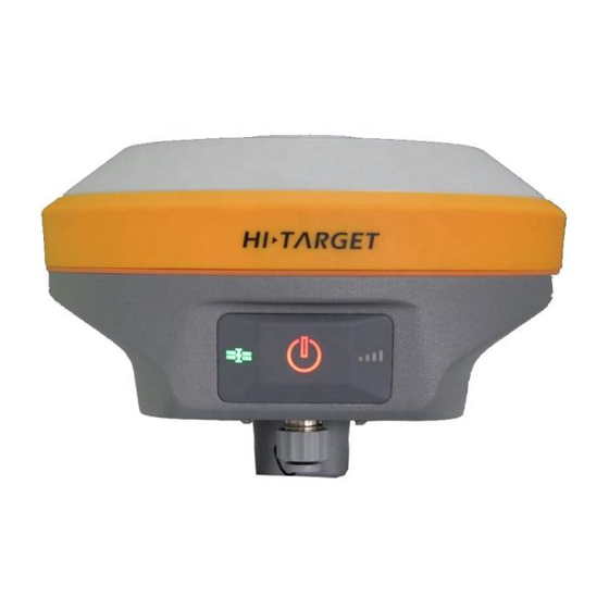
Receiver Appearance The product appearance is divided into three sections,upper cover, bottom cover and control panel. upper cover bottom cover control panel Figure 2-1 Control Panel V90Plus middle frame for the control panel of the receiver, the control panel includes a power switch button, a button to include all the features of V90Plus receiver set. -
Page 12: Upper Cover
HI-TARGET 接收机介绍 Satellite light (green light) status light (red and green light) power light (red and green light) Power Button Functions: Startup,shutdown,operating mode switching, the mode switching confirmation status query, automatically set the base station, forced shutdown, reset the board and so on. - Page 13 speaker 1- Screw connection 2- 3-USB interface and protective plug 4-GPRS/ Antenna Interface 5- Five-pin plug socket and protection 6- Battery compartment 7- SD card slot 8-SIM card slot 9- Battery Cover 10-SLC Power Block. Figure 2-4 ◇ connection screw: for the instrument fixed to the base or the pole. ◇...
-
Page 14: Batteries
HI-TARGET 接收机介绍 ◇ Five-pin socket: For connection to the host and external data links and external power source. ◇ battery compartment: for housing lithium batteries. ◇ SD card slot: SD card for housing, can store large-capacity static data. ◇ SIM card slot: for receiving USIM / SIM card for data link communications and remote control. -
Page 15: Environmental Requirements
Close Open Figure 2-5 Positive pole Negative pole Figure 2-6 Environmental Requirements The receiver shall operate in dry working environment regardless of waterproof materials. In order to advance the stability and service cycle of receiver, the receiver shall be prevented from extreme environment, such as: ◇... -
Page 16: Electronic Jamming
HI-TARGET 接收机介绍 Electronic Jamming The receiver shall not be installed in the place near to strong electric power and interference signal, such as: ◇ Oil duct (spark plugs) ◇ Generator ◇ Battery-operated motor cycle ◇ DC-AC power supply changeover equipment ◇... -
Page 17: Elementary Operation
C H A P T E R Elementary Operation This chapter describes: ■ Control panel ■ Function Key ■ Status Inquiry ■ LED Function ■ Start and stop receiver ■ Reset Motherboard ■ Automatic setting station ■ Static collection ■ Static data storage ■... - Page 18 HI-TARGET ■ U disk data download ■ Firmware ■ Electronic bubble ■ Electronic bubble calibration ■ WiFi password settings ■ Power Supply System ■ Radio frequency settings ■ SIM card / USIM card ■ Micro SD Card...
-
Page 19: Control Panel
Control panel Most settings and operations of receiver are completed using two keys on control panel. Power light Satellite light Status light Figure 3-1 Function Key Table 3.1 Description of keys operation time Operation name Note Shutdown state, long press the button one second boot Boot mode, three seconds ≤... -
Page 20: Status Inquiry
HI-TARGET Status Inquiry See Schedule Reset Motherboard The boot state, long press the button more than 6 seconds, voice reporting second sound "ding dong", release the button, reset motherboard Forced shutdown The boot state, long press the button more than 8 seconds, forced shutdown Status Inquiry Table 3.2 Key Functions... -
Page 21: Start And Stop Receiver
fast flash Tip Power: 1-4 flash per minute under the direction of electricity Signal light when you did not use GSM / WiFi client (Status Green) Long-term GSM / WiFi connected to the server lighting Slow flash GSM has landed on the 3G / GPRS network or connect to WiFi hotspots fast flash GSM is landing when prompted 3G / GPRS... -
Page 22: Reset Motherboard
HI-TARGET trap power lights on previous startup and Voice prompt of data button for link mode 1 second Shutdo Long indicator Shutdown music press lights off power button for 3 seconds Reset motherboard The boot state, long press the button more than 6 seconds, voice reporting second sound "ding dong", release the button, reset the motherboard. - Page 23 memory card). After the static data file must be downloaded to a computer for processing a static post-processing software. Working mode switch: You can also switch by handheld, please NOTE: refer to the specific operation "Hi-Survey Software User's Guide" → equipment → Accessibility → static capture settings. Static acquisition step 1.
-
Page 24: Static Data Storage
HI-TARGET 3, the recording name, instrument number, instrument height, began observing time. 4, boot, set the host to the static measurement mode. Satellite Blinking is searching for satellites. Satellite into long bright lights from flashing status indicates locked satellites. Status lights flash once every few seconds, indicating that the acquisition of one epoch. -
Page 25: Rtk Data Storage
figure 3-3 Note:When the receiver inside and outside the storage space is less than 2MB, data light (red state) flash, and will stop recording data, the existing data files will not be overwritten. RTK data storage iHand20 handheld Haida V90Plus receiver can be connected via WiFi, Bluetooth or network, when work began after the setup is complete, the memory card handheld, you can book by hand random configuration data cable data collected RTK RTK data storage downloaded onto your computer. -
Page 26: U Disk Data Download
HI-TARGET For more information about the hand-book, read "Hi-Survey Software User's Guide." U disk data download Receiver file management is stored by USB drive. It can be used upon inserting and download by dragging directly without download programs. It can only download static data and unable to write or read the receiver. -
Page 27: Firmware
Figure 3-6 Note: the static files in removable disk can be deleted by GNSS receiver management software rather than deleting directly. Firmware The receiver uses the 3G network, the host firmware can be automatically upgraded (You can refer to: "Hi-Survey Software User's Guide" → equipment →... -
Page 28: Electronic Bubble
HI-TARGET corresponding voice prompts to upgrade if the upgrade fails again or contact technicians. Electronic bubble After Hi-Survey in demo mode, the built-in GPS or connect V90Plus, support electronic bubble measuring software interface schematic display electronic bubble position, the user can select the automatic collection in electronic bubble automatic measurement and automatic sampling sites according to the electronic bubble state. -
Page 29: Electronic Bubble Calibration
Figure 3-8 Figure 3-9 Electronic bubble calibration When connecting V90Plus receiver, users can calibrate the electronic bubble under the [Accessibility]. Figure 3-10... - Page 30 HI-TARGET To do the following: [Device] → [Accessibility] → [electronic bubble calibration] Figure 3-11 V90Plus receiver placed outside the strict leveling base remain stationary until the receiver locks satellite, ready when you are ready click on [Start] button to bring up the calibration check box.
-
Page 31: Wifi Password Setting
Click the pop-up confirmation box OK button, the hosts began to calibrate the electronic bubble. Figure 3-13 Figure 3-14 NOTE: Electronic bubble age calibration period recommended value is set to 30 days, more than the set number of days without calibration, the receiver will not work! WiFi password setting Set V90Plus host as a WiFi hotspot when connected to a password. - Page 32 HI-TARGET Figure 3-15 1, WiFi factory default password See Schedule 3; Note: 2. If you have forgotten your own set of WiFi password, you can "GNSS receiver management software V1.4.2" → WiFi password, enter the password and click OK to. Specific methods of operation...
-
Page 33: Power Supply System
Power Supply System Battery installation and removal Installation 1, the battery cover and push back gently press the metal buckle. Figure 3-16 2, the battery cover up to open the shells. - Page 34 HI-TARGET Figure 3-17 Open Close 图 3-18 3, toward the end of marked "Close" gently press and push (red arrow) can complete the battery installation. Remove: Along with the name "Open" and hold the direction of launch, pour out the battery,the battery complete uninstall.
- Page 35 Battery, charger table 3.5, the battery charger model Name Model Lithium Battery BL-5000 Charger CL-8410/ CL-4400...
- Page 36 HI-TARGET Power supply Table 3.6 Power Supply powe Power Lithium batteries; 5-pin external power supply socket Power DC power supply: 6 ~ 28V range V90Plus receiver can also be powered via 5-pin socket bottom of the main external power supply.
- Page 37 Charging BL-5000 rechargeable lithium battery must use a dedicated CL-8410 / CL-4400 lithium battery charger, charging time is about 7 hours. CL-8410 Battery Charger charging indicator light is red during charging, charging is completed the light turns green, continue to charge 1 to 1.5 hours, then the battery is fully charged.
-
Page 38: Sim Card/Usim Card
HI-TARGET Close Charge indicator Power Indicator Figure 3-20 2, along the "Close" direction, the red arrow shown in the figure above, push the battery until it clicks. 3. After connecting the power, "charging indicator" is displayed as red light is charging. - Page 39 USIM WCDMA(ZHD/VRS) Card GPRS(ZHD/VRS) GPRS(ZHD/VRS) Card Installation card Use V90Plus Receivers RTK jobs, you need to prepare SIM or USIM card and open the corresponding data communication services. The required number of cards, depending on your system configuration RTK survey. Each host and each handheld for an installation card.
-
Page 40: Micro Sd Card
HI-TARGET 2, SIM card slot is consistent with the notch direction. Figure 3-22 3, the SIM card in the deck, the front (with metal contact surface) down into the slot. Figure 3-23 4, the entire SIM card into the slot to complete the installation. - Page 41 buy zone configuration. Ordinary SD card Micro SD card volume by volume to be large to fit V90Plus use. V90Plus largest to 16GB Micro SD card. 2. The iHand20 induction area close V90Plus sensing area, Hi-Survey will automatically start V90Plus Bluetooth connection. iHand20 located on the back of the sensing area: NFC sensor area V90Plus located atop the sensing area:...
-
Page 42: Technical Parameters
HI-TARGET C H A P T E R Technical parameters This chapter describes: ■ GNSS section ■ Receiver Accuracy ■ Interface ■ Function keys and indicators ■ Physical Characteristics ■ Environment... -
Page 43: Gnss Section
GNSS Section ◇ GPS:Synchronous tracking L1 ◇ BDS:Synchronous tracking B1、B2 ◇ GLONASS:Synchronous tracking L1 C/A、L1 P、L2 C/A ◇ SBAS:Synchronous tracking L1 C/A、L5 ◇ GIOVE-A:Synchronous tracking L1 BOC、E5A、E5B E5AltBOC (Optional) ◇ GIOVE-B:Synchronous tracking L1 CBOC、E5A、E5B E5AltBOC (Optional) ◇ GALILEO: (Upgrade Reserved) ◇... -
Page 44: Interface
HI-TARGET Height:±(15+1×10 D) mm Interface ◇ 1 x RS232 serial interface ◇ 1 x Mini USB interface ◇ 1 x SIM card interface ◇ 1 x SD card interface ◇ 1 x 3G / GPRS antenna interface ◇ 1 xBluetooth interface ◇... -
Page 45: Environment
◇ Weight: 1.0kg (without lithium battery) ◇ Anti-2 m natural drop, anti-two meters underwater temporary immersion. ◇ Built-in 5000mAh high-capacity lithium-ion battery. Voltage: 7.4V, a new battery continuous working time: 12 hours static, GPRS mode 9 hours, 2W station transmitting 7 hours. ◇... -
Page 46: Socket And Main Accessories
附表 1 出产默认频率表 C H A P T E R Socket Main Accessories This chapter describes: ■ Preface ■ Five-pin socket ■ Five-wire ■ Mini USB interface ■ Mini USB wire ■ Antenna Interface ■ Antenna... -
Page 47: Preface
The chapter will introduce the appearance and application of main interface of receiver and accessories. The following equipment does not represent all users purchased V90 Plus. According to different configurations, the specific configuration shall be subject to the delivery order upon purchasing. -
Page 48: Five-Wire
附表 1 出产默认频率表 2, All the companies are in circular socket counterclockwise positive start numbering pin; pin round plugs are numbered starting with welding face counterclockwise. 3,All the above data (TXD), the (RXD) signals to receivers explained. TXD transmit data to the receiver signal line, RXD received data to a receiver line. -
Page 49: Mini Usb Interface
Five-pin socket:For connecting the radio receiver and five-pin plug socket. Plug the red dot Socket red dot Figure 5-4 Mini USB Interface Mini USB intreface Figure 5-5 For connection to the host and external devices, upgrade firmware and download the static data, can also be used as USB to serial port using a special mode of operation (need to install drivers, see Annex 4). -
Page 50: Antenna Interface
附表 1 出产默认频率表 Standard USB interface Mini USB interface Figure 5-6 USB cable, one end is a standard USB connector on one end and Mini Mini USB interfaces; an external device connected to the host for data transmission. Antenna Interface Antenna Interface Figure 5-7 3G / GPRS... -
Page 51: Schedule 2 Control Panel Lights
Schedule 2 control panel lights Table 2 control panel lights illustrate Operating Meaning Power light Normal voltage: the battery> 7.6V, foreign> 12.6V (yellow) Power light Normal voltage: 7.1V <internal battery ≤ 7.6V, 11V (red) <foreign ≤12.6V Slow Brown: the battery ≤7.1V, foreign ≤11V flash Fast It indicates that the battery: Flash indicate the charge per... - Page 52 附录 Schedule 4 USB virtual serial port driver installation 1)First, it confirms that our equipment has been launched USB virtual serial port functions. This step requires the use of the company's Android hand book binding Hi-Survey software to view and set in the "Device" → "Accessibility"...
- Page 53 4)Open Systems "Device Manager" in the "other" option, you will see two unidentified device. "CDC Serial" and "RNDIS". Figure 2 5)Click "CDC Serial", right-select "Update Driver Software" in the pop-up window, select "Browse my computer for driver software (R)", then select the file drivers "linux_cdc_seial.inf"...
- Page 54 附录 Figure 3 6)If you search for a valid drive, pop occurs. Figure 4...
- Page 55 In this case, select the "Always install driver software." After a successful installation displays the following information. Figure 5 7)Then you can see the serial device, and serial number in the Device Manager.
- Page 56 附录 Figure 6 Since we did not use to "RNDIS" device, so it can not install the driver.
- Page 57 FCC Caution: Any changes or modifications not expressly approved by the party responsible for compliance could void the user's authority to operate this equipment. This device complies with Part 15 of the FCC Rules. Operation is subject to the following two conditions: (1) This device may not cause harmful interference, and (2) this device must accept any interference received, including interference that may cause undesired operation.
Need help?
Do you have a question about the V90 Plus and is the answer not in the manual?
Questions and answers