
Related Manuals for Hi-Target V100


Summary of Contents for Hi-Target V100
- Page 1 Manual Revision File number:YFZ-2015-0741 Revision Description Revision Date Level Nov.2015.04 V100 GNSS RTK System User Manual A/1 I ...
- Page 2 Preface Introduction Welcome to use Hi-target V100 receiver, this introduction is applicable to Hi-Target V100 products. V100 is a new type of GNSS receiver used for measurement. The introduction describes how to install, set and use V100 products. Experience Requirement In order to help you better use Hi-Target series products, Hi-Target suggests you carefully reading the instruction.
- Page 3 Before using the products, please carefully read the operating instruction, and it will help you better use the product. Hi-Target Surveying Instrument Co., Ltd will not assume the responsibilities if you fail to operate the product according to the requirements in operating instruction, or operate the product wrongly because of failing to understand the operating instruction.
- Page 4 Relevant Information You can get this introduction in the following ways: 1. After purchasing hi-target V100 receiver,there will be “V100 GNSS RTK System User Manual” in the instrument container to guide you how to operate instrument.
- Page 5 2. Log in hi-target official website, download the electronic version introduction in “Download Center” “Manual” → “Surveying Products” → Advice If you have any advice or suggestion on V100, please call us or Dial the national hotline: 400-678-6690. Your feedback information will improve the production quality more. V ...
-
Page 6: Table Of Contents
Content Content Product Introduction ........1 Preface ..........2 Product Characteristics ....... 3 Cautions for Use ........3 Introductions to Receiver ......... 5 Receiver Appearance ........6 Control Panel ......... 6 Upper Cover ........... 7 ... - Page 7 V100 GNSS RTK System User Manual Preface ..........33 Five-pin Socket ........33 Five-wire ..........34 Mini USB Cable ........36 Measurement Bench Marker ......37 Schedule 1 control panel lights ......38 Schedule2 factory default parameters ..... 39 ...
-
Page 9: Product Introduction
Product Introduction C H A P T E R Product Introduction This chapter describes: ■ Preface ■ Product Characteristics ■ Cautions for Use 1 ... -
Page 10: Preface
Product Introduction Preface V100 is a new subminiaturized type of GNSS receiver used for measurement pushed forward by Hi-Target Brand, used a delicate design, Magnesium alloy construction,... -
Page 11: Product Characteristics
Designed for the Android development of customized smart metering software--Hi-Survey; A key Multifunction; New subminiaturized fuselage, Magnesium alloy structure, more solid; Cautions for Use V100 receiver used Chemical resistance and impact resistance design , but we also need carefully use and 3 ... - Page 12 Product Introduction maintenance the sophisticated instruments. Warning: the receiver shall be in stipulated temperature range upon using and storage. The detailed requirements are shown in ChapterⅣ: Technical Parameters—>...
-
Page 13: Introductions To Receiver
V100 GNSS RTK System User Manual C H A P T E R Introductions to Receiver This chapter describes: ■ Receiver Appearance ■ Control Panel ■ Upper Cover ■ Bottom Cover ■ Power Supply System ■ Environmental Requirements ■ Electronic Jamming 5 ... -
Page 14: Receiver Appearance
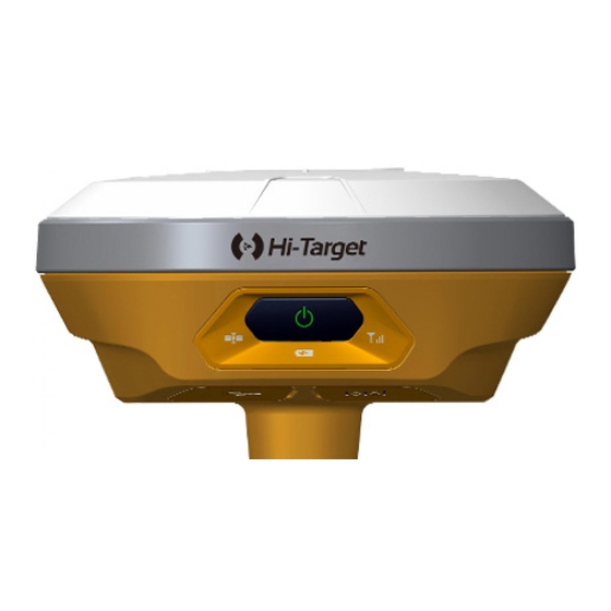
Introductions to Receiver Receiver Appearance The product appearance is divided into three sections,upper cover, bottom cover and control panel. upper cover bottom cover control panel Figure 2-1 Control Panel The control panel includes a power switch button, three indicators, namely satellite lights, power light (bi-color light), signal light (bi-color light). -
Page 15: Upper Cover
V100 GNSS RTK System User Manual and so on. Upper Cover Color Mode Loss Prevention boss Figure 2-2 Loss Prevention boss: boss can effective anti-wear; Color Mode: appearance of the structure, Clear , beautiful, drop Bottom Cover Including battery compartment, five-pin socket,Mini USB interface. - Page 16 Introductions to Receiver 1- Screw connection 2- Battery compartment 3- Five-pin socket 4-Mini USB interface 5- protective plug Figure 2-3 Connection screw: for the instrument fixed to the base or the pole.
-
Page 17: Power Supply System
V100 GNSS RTK System User Manual Protective plug: socket for dust and waterproof. Note: If it is unnecessary to use five-pin socket, and USB interface, please cover the rubber plug to prevent dust. Power Supply System Battery and adapter Table 2.1 Battery, adapter type... - Page 18 Introductions to Receiver Figure 2-5 Recharge V100 lithium battery shall use PSAI10R-050Q power adapter to charge, about 7 hours of charging time. only the battery and charger configured Warning: 1.
- Page 19 V100 GNSS RTK System User Manual Battery cover button Figure 2-6 2) Align battery pole with battery compartment pole, boost until it flush with battery cover and the mental button upspring. battery pole Metal button Figure 2-7 11 ...
- Page 20 Five-pin socket:DC power 6-28V/1A supply Upon external power supply, the host will automatically detect the voltage of lithium battery and external power supply, and supply power choosing higher voltage. As for external power supply, it shall use the special power specified by Hi-Target.
-
Page 21: Environmental Requirements
V100 GNSS RTK System User Manual The service life of lithium battery will NOTE: 1. decrease along with the decrease in temperature increase charging-discharging times. A new 6300 mAh lithium battery can be used for 7 hours upon collection of static data or rovel operation. -
Page 22: Electronic Jamming
Introductions to Receiver Corrosive liquids or gases Electronic Jamming The receiver shall not be installed in the place near to strong electric power and interference signal, such as: ... -
Page 23: Elementary Operation
V100 GNSS RTK System User Manual C H A P T E R Elementary Operation This chapter describes: ■ Control Panel ■ Function Key ■ LED Function ■ Working Pode Switch ■ Rovel Handheld Difference ■ Static Collection ■ Static Data Storage ■ Static Data Download ■... -
Page 24: Control Panel
Elementary Operation Control Panel Most settings and operations of receiver are completed using a key on control panel. Power key Satellite light Status light Power light Figure 3-1... -
Page 25: Led Function
V100 GNSS RTK System User Manual automatically set the base station Operating mode Double-click the button to enter switching the operating mode switching, double-click each time a working mode switch(switch between static and RTK mode) Status Inquiry Click power light ,red light flash flashing, displays power... -
Page 26: Working Mode Switch
Elementary Operation 1:0%~25% 2:25%~50% 3:50%~75% 4:75%~100% Signal light Static mode (Status Green) Long-term RTK mode lighting Data light Slow flash 1. RTK mode: flash as difference data interval (Status Red) 2. -
Page 27: Rovel Handheld Difference
V100 GNSS RTK System User Manual signal light (red) flash as difference data interval. Working mode switch: You can also switch NOTE: by handheld, please refer to the specific operation "Hi-Survey Software User's Guide" RTK mode setting : equipment → base\rovel → data line; static mode: setting equipment →... - Page 28 Elementary Operation Figure 3-2 Figure 3-3 Handheld difference rovel working mode setting: In rovel setting interface, select data line “handheld”, select server, setting IP, port, group number and other parameters, click “setting”...
- Page 29 V100 GNSS RTK System User Manual base and rovel should setting the same parameters. “Network”: ZHD and CORS, select ZHD when using hi-target server, select CORS when using CORS network. Figure 3-4 Figure 3-5 Checking difference transmitting state: check difference transmitting state in suspend: :handheld difference(transmitting) : handheld difference (not transmitting) 21 ...
-
Page 30: Static Collection
Elementary Operation Checking difference network state: click to the “difference network state” interface. If user have connected receiver and set as rovel handheld difference operation,click directly “disconnect”... - Page 31 V100 GNSS RTK System User Manual shall be measured to the center point mark stone on top of the instrument of measurement reference member.V100 receiver measuring reference member radius 0.130m. measurement reference height measurement point Figure 3-7 3. Record point name, instrument number, instrument height, beginning observing time.
-
Page 32: Static Data Storage
Static Data Storage Collected GNSS static data is stored in "static" disk that 8GB internal storage of V100 receiver, effective storage space is 6.6GB, includes two folders: log and gnss, log folder stores log information, the data format storage in gnss folder is * .gns. -
Page 33: Static Data Download
V100 GNSS RTK System User Manual Figure 3-8 Note:When the receiver storage space is less than 10MB, data light (red) fast flash, and it stop recording data, the existing data files will not be overwritten. Static Data Download Receiver file management download directly without download programs in the way of U disk storage. It can only download static data and can’t write or read the receiver. -
Page 34: Firmware Upgrading
Elementary Operation file. Figure 3-9 The steps of modify point name and antenna height of downloaded static file are: 1. Choose *. GNS files and double click the mouse. 2. - Page 35 V100 GNSS RTK System User Manual way. Figure 3-11 1. Open receiver, connect to computer by a random configuration USB cable. Open “my computer”, there will be "update" upgrading disk. 2. Copy host firmware (it can be downloaded from the official website or obtained from the technician) to "update"...
-
Page 36: Technical Parameters
Technical parameters C H A P T E R Technical Parameters This chapter describes: ■ GNSS Configuration ■ System Configuration ■ Built-in Communication ■ Control Panel ■ External Interface ■ Electric Characteristics ■ Physical Characteristics ■ Environment Characteristics ■ Private Cloud Service... -
Page 37: Gnss Configuration
V100 GNSS RTK System User Manual GNSS Configuration System core: use international first-class PCC new efficient intelligent real-time core Channel number:220 BDS:B1、B2 GPS:L1 C/A、L2E、L2C、L5 GLONASS: L1 C/A、 L1 P、 L2 C/A (Limited GLONASS M and L2P) GALILEO:Upgrading reserve Output format: ASCⅡ: NMEA-0183 and binary : Trimble GSOF ... -
Page 38: System Configuration
Technical parameters Initialization reliability : >99.9% Data update rate : <20Hz System Configuration Operation system:intelligent real-time system boot time: 1s Data storage:built-in 8GB storage Built-in Communication Daul mode Bluetooth communication Control Panel Panel: one key ... -
Page 39: Physical Characteristics
V100 GNSS RTK System User Manual Physical Characteristics Core control chip CotexA8, built-in 16GB Flash memory Size:127.5mm×57mm Weight: ≤700g (lithium battery) Material:magnesium alloy material Environment Characteristics Protection class:IP67; protect 2m temporary soaking underwater, Completely prevent dust Working temperature: -40 ℃ ~ 60 ℃... -
Page 40: Socket And Main Accessories
Socket and Main Accessories C H A P T E R Socket Main Accessories This chapter describes: ■ Preface ■ Five-pin Socket ■ Five-wire ■ Mini USB Wire ■ Measurement Bench Marker... -
Page 41: Preface
The chapter will introduce the appearance and application of main interface and accessories of V100. The following equipment does not represent all V100 users purchased. There will be different according to different configurations, the specific configuration shall be subject to the delivery order upon purchasing. -
Page 42: Five-Wire
Socket and Main Accessories 2. All the circular sockets of this company start numbering pin in counterclockwise positive; circular pins start numbering pin in welding face counterclockwise. 3. All the above data out(TXD), in(RXD) signals explain by receivers. TXD is transmitting receiver data signal line, RXD is receiving receiver data signal line. - Page 43 V100 GNSS RTK System User Manual five-pin socket five-pin socket Figure 5-3 Five-wire: Connecting host and External radio, transmitting difference data; Plug the red dot Socket red dot Figure 5-4 Warning: 1. when connecting various plugs of receiver, it shall align the red point in line joint at the red point in receiver 35 ...
-
Page 44: Mini Usb Cable
Socket and Main Accessories socket, or it will damage the receiver socket and plugs of various lines. 2. When plug out the plug, directly grasp the sliding collar and pull out the plug with effort. It shall not rotate the plug. 3. After using the cable it shall place the cable in the place that are difficult for extrusion to prevent damaging the plug. -
Page 45: Measurement Bench Marker
V100 GNSS RTK System User Manual one end and Mini USB interfaces. Measurement Bench Marker measurement height point measurement bench marker Figure 5-7 Figure 5-8 37 ... -
Page 46: Schedule 1 Control Panel Lights
附录 Schedule 1 control panel lights Table 1 control panel lights illustrate Operating Meaning Power Light Long-term Full battery lighting (Green) Power Light Long-term Full battery voltage: internal battery≥3.9V(100% lighting power) (Yellow) Power Light Long-term Normal voltage: 6% <internal battery power ≤99% lighting (Red) Slow flash... -
Page 47: Schedule2 Factory Default Parameters
V100 GNSS RTK System User Manual Schedule2 factory default parameters Table 2 Factory default parameters Options Content The factory set parameters System Working mode Rover parameters Data Link Handheld difference Differential Mode Text format RTCM(3.2) Height cut-off angle boot boot GLONASS boot Static collection interval... - Page 48 Main performance index Motherboard BD970 Trimble 220channels Antenna Small measuring Hi-Target Surveying 51dB zero phase antenna Instrument Co., Ltd. Databoard ZHD20150010B Hi-Target Surveying [PCBA] Instrument Co., Ltd. FCC Caution: Any changes or modifications not expressly approved by the party responsible for compliance could void the user's authority to operate this equipment.
- Page 49 V100 GNSS RTK System User Manual -- Connect the equipment into an outlet on a circuit different from that to which the receiver is connected. -- Consult the dealer or an experienced radio/TV technician for help.
Need help?
Do you have a question about the V100 and is the answer not in the manual?
Questions and answers