Table of Contents
Advertisement
Quick Links
Introduction
The introduction is applicable to Hi-Target V60 products. V60
is a new type of GNSS receiver used for measurement. The
introduction describes how to install, set and use V60
products.
In order to help you better use Hi-Target series products,
Hi-Target suggests you carefully reading the instruction. If you
are
unfamiliar
www.hi-target.com.cn/en/
Tips for safe use
Note: the contents here generally are special
V60 GNSS RTK System Operation Instruction
Preface
with
V60
products,
operations, needing your special attention.
Please read the contents carefully.
please
refer
to
I
Advertisement
Table of Contents

Related Manuals for Hi-Target V60


Summary of Contents for Hi-Target V60
- Page 1 V60 GNSS RTK System Operation Instruction Preface Introduction The introduction is applicable to Hi-Target V60 products. V60 is a new type of GNSS receiver used for measurement. The introduction describes how to install, set and use V60 products. In order to help you better use Hi-Target series products, Hi-Target suggests you carefully reading the instruction.
- Page 2 Before using the products, please carefully read the operating instruction, and it will help you better use the product. Hi-Target Surveying Instrument Co., Ltd will not assume the responsibilities if you fail to operate the product according to the requirements in operating instruction, or operate the product wrongly because of failing to understand the operating instruction.
- Page 3 V60 GNSS RTK System Operation Instruction We have checked the consistency between contents in instruction and software & hardware, without eliminating the possibility of deviation. The pictures in operating instruction are only used for reference. In case of inconformity with...
-
Page 4: Table Of Contents
Introductions to Receiver Content Product Introduction ........1 Preface ..........2 Product Characteristics ........3 Cautions for Use ......... 4 Introductions to Receiver........ 6 Receiver Appearance ........7 Control Panel ..........7 Upper Cover ..........8 Bottom Cover ..........9 Five-core and Eight-core Sockets ...... - Page 5 V60 GNSS RTK System Operation Instruction Firmware ..........37 Static Collection and Data Transmission ....38 Preface ..........40 Static Measurement ........40 U Disk Data Download ........42 Operations of Static Management Software ....43 Technical Parameters ........46 GNSS Part ..........47 Receiver Precision ........
-
Page 7: Product Introduction
V60 GNSS RTK System Operation Instruction C H A P T E R Product Introduction This chapter describes: ■ Preface ■ Product characteristics ■ Cautions for use... -
Page 8: Preface
Introductions to Receiver Preface V60 is a new type of GNSS receiver used for measurement pushed forward by Hi-Target recently. The receiver is provided with 1G mass storage and one SD card extendable slot, which can record static data in forms of GNS and Rinex simultaneously. -
Page 9: Product Characteristics
V60 GNSS RTK System Operation Instruction case of loss or damage in the product and its accessories, please immediately contact with local office or dealers; please carefully read the operating instruction before carrying, transporting using product. Product Characteristics ◇ Obtain the CE0890 certification ◇... -
Page 10: Cautions For Use
Introductions to Receiver ◇ 128x64 resolution; 1.54-inch liquid crystal display The user can flexibly set the instrument and observe the operations of instrument through display Cautions for Use As a precise instrument, the receiver shall be used and maintained carefully regardless of the materials resistant to chemical agent and impact. - Page 11 V60 GNSS RTK System Operation Instruction responsible for compliance could void the user’s authority to operate the equipment. This equipment has been tested and found to comply with the limits for a Class B digital device, pursuant to Part 15 of the FCC Rules.
-
Page 12: Introductions To Receiver
Introductions to Receiver C H A P T E R Introductions to Receiver This chapter describes: ■ Receiver appearance ■ Control panel ■ Upper cover ■ Bottom cover ■ Five-core and eight-core sockets ■ Batteries ■ Environmental requirements ■ Electronic jamming... -
Page 13: Receiver Appearance
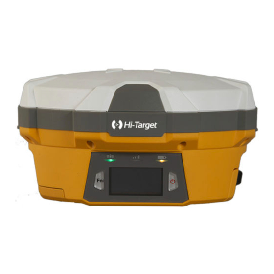
Control Panel The control panel includes Fn key (function key), power button, LED display and 3 indicator lights which are satellite light, status light (bi-color light) and power light (bi-color light). Two buttons cover all functions of V60 receiver setting. -
Page 14: Upper Cover
Introductions to Receiver Figure 2-2 Satellite light (green light), status light (red and green light) and power light (red and green light) Function key: set work mode, data link, satellite elevation, sampling interval, reset receiver, etc. Power button of startup & shutdown: set confirmation and inquire current work mode. -
Page 15: Bottom Cover
V60 GNSS RTK System Operation Instruction Convex plate Bottom Cover Include battery slot, five-core socket, eight-core socket, trumpet, etc. - Page 16 Introductions to Receiver 1. Eight-core socket and protection plug; 2. Five-core socket and protection plug; 4. Connecting screw; 5. Battery slot; 6. Vibrating needle power socket; 7. SIM slot; 8. SD card slot; 9. Trumpet Figure 2-3 ◇ Eight-core socket: it is used to connect the receiver, computer, handbook and external power supply, and load and delete the data.
-
Page 17: Five-Core And Eight-Core Sockets
V60 GNSS RTK System Operation Instruction ◇ Connecting screw: it is used to fasten the instrument to base or centering rod ◇ Battery slot: it is used to place lithium battery ◇ Vibrating needle power socket: it is used to connect the lithium battery and host ◇... - Page 18 Introductions to Receiver Figure 2-5 1. Five-core socket: it is also called as COM2/PW2, which is used to connect the host and external data chain, and external power supply. 2. Eight-core socket: it is also called as COM1/USB/PW1, which is used to connect the computer and controller, set parameters, download and delete files.
-
Page 19: Batteries
V60 GNSS RTK System Operation Instruction ground ◇ All round sockets are numbered anticlockwise in positive face; all round plugs are numbered anticlockwise in weld face. ◇ All TXD and RXD are described by the receiver. EXD is the transmit data line of receiver; RXD is the receive data line of receiver. -
Page 20: Environmental Requirements
Introductions to Receiver Figure 2-6 Environmental Requirements The receiver shall operate in dry working environment regardless of waterproof materials. In order to advance the stability and service cycle of receiver, the receiver shall be prevented from extreme environment, such as: ◇... - Page 21 V60 GNSS RTK System Operation Instruction from human body.
-
Page 22: Elementary Operation
Elementary Operation C H A P T E R Elementary Operation This chapter describes: ■ Power supply ■ Control panel ■ Function Key ■ Start and stop receiver ■ SIM card/USIM card ■ Static data storage ■ RTK data storage ■... -
Page 23: Power Supply
V60 GNSS RTK System Operation Instruction Power Supply Battery cover plate installation and re moval Installation: obliquely insert the two raised areas on battery cover plate into the slot; press downwards and fasten the battery cover upon the sound of “bang”; place the pushing and dialing key in locking status. - Page 24 Elementary Operation Figure 3-2 Removal: push out along with “open” side and pour out the battery to dismantle the battery. Power supply mode Table 3.1 Power supply mode of V60 receiver Power Power Built-in lithium battery, eight-core socket/five-core socket external supply...
- Page 25 V60 GNSS RTK System Operation Instruction socket/five-core socket external power supply. Where: The receiver will automatically start after energizing eight-core socket external power supply The receiver will start through pressing the power button on control panel after energizing five-core socket external power supply.
- Page 26 Recharge BL-5000 lithium battery shall use Hi-Target CL-4400 lithium battery charger to charge. About 7 hours of charging time CL-4400 charger is designed with charge lamp. The lamp is red during charging process and turns green upon finishing charging.
-
Page 27: Control Panel
V60 GNSS RTK System Operation Instruction Control Panel Most settings and operations of receiver are completed using two keys on control panel. Status light Power light Satellite light Power key LCD Display Function Key Figure 3-4 Table 3.2 Description of keys operation time... - Page 28 Elementary Operation Super long-press The key operation shall be more than 6 operation seconds, upon two counts of “ding-dong” Slow flashing Light on greater than 0.5 seconds Quick flashing Light on less than 0.3 seconds...
-
Page 29: Key Functions
V60 GNSS RTK System Operation Instruction Key Functions V60 GNSS RTK system can on or off LCD panel display through double clicking power key. High-definition LCD panel can complete the basic requirements of receiver with two keys, which also can flexibly set three work modes, base, rover and static mode. - Page 30 Elementary Operation Visible satellite Remaining power of host PDOP value File name of static data Working mode Figure 3-6 Table 3.3 Description of key operation (LCD state) Function Operation Keys Content On / Off LCD screen Double click power key Click Fn key and the choice box is Click Fn key Selection menu...
- Page 31 V60 GNSS RTK System Operation Instruction PTK mode is indicated as from left to right: Click Fn key Data link; difference parameters; work mode; system information Data link menu contains three Click Fn key and skip optional data chain models: GSM, choice box;...
- Page 32 Elementary Operation Static parameter setting Elevation angle 0 ° - 30 ° Sampling interval: 1s, 2s, 5s, 10s, 15s, 30s 1. Choose System information provides the click power key to return current coordinates of receiver, sky to previous menu; plot and system state for users to inquire.
- Page 33 2. As for GSM data link parameter setting interface, the panel can be effective only setting Hi-Target server IP: 202.96.185.34, port: 9000, group number (7 bits), team number (3 bits); if connected by CORS, parameter setting shall be operated through Hi-Target handbook software.
- Page 34 Elementary Operation into key mode, in order to economize power consumption. The user can double click power key to restart LCD. Use keys to off LCD. If there is no LCD, it can switch the work mode through two keys and provide voice service to assist the users in finishing operation.
-
Page 35: Start And Stop Receiver
V60 GNSS RTK System Operation Instruction Reset Super long Fn Reset motherboard If the handbook Bluetooth fails to receiver key press connect with the host after resetting the host, it can adjust the host in static mode and then reset after data collection. - Page 36 Elementary Operation measurement system. Each host and controller installs one card. The receiver supports SIM card and USIM card Table 3.6 Description of SIM card / USIM card USIM GPRS(ZHD/VRS) card SIM card GPRS(ZHD/VRS) Before using SIM card or USIM card, please ensure GPRS data business has been opened.
-
Page 37: Static Data Storage
V60 GNSS RTK System Operation Instruction Figure 3-9 Static Data Storage Dual format storage for static data It can use Hi-Target RTK software to start or close static data collection function under standard form in GPS information advanced settings RTK setting; it shall open or close static data collection function under standard form before recording static collection;... - Page 38 Elementary Operation Note: when the storage space of receiver is less than 2M bytes, the data light (red light) will flash quickly and stop recording data. The current data file will not be covered. External SD card data storage The receiver shall support SD card data. SD card slot is installed under the battery.
- Page 39 V60 GNSS RTK System Operation Instruction Figure 3-11 Figure 3-12 SD card SD card installation procedure 1. Dismantle battery cover plate; take down the battery and disclose SD card slot. 2. Push up the mental cover according to the prompts; open the upper cover of SD card and place SD card.
-
Page 40: Rtk Data Storage
Elementary Operation 3. Push down the upper cover and push outside to fasten the upper cover. Figure 3-14 Note: it shall turn off the power of receiver before installing card. If SIM card is installed under startup state, the receiver will fail to detect SIM card, and the setting of work mode will be ineffective. -
Page 41: Reset Receiver
V60 GNSS RTK System Operation Instruction Figure 3-15 Reset receiver Super long-press Fn key and reset the motherboard. The motherboard can be recovered to delivery state. Warning: the reset of motherboard will prolong the first locking time of receiver. It is necessary to reset the work mode of receiver. - Page 42 Elementary Operation Figure 3-16 Warning: Before formatting the receiver, it shall ensure all useful data in receiver are copied to the computer. The data will not be recovered upon deletion or formatting.
-
Page 43: Firmware
V60 GNSS RTK System Operation Instruction Firmware The receiver can upgrade firmware through USB drive. Upgrade steps of firmware: Figure 3-17 1. Firstly, it shall open the receiver and use Y-type data line to connect with USB port of computer. Open “my computer”, and “update”... -
Page 44: Static Collection And Data Transmission
Static Collection and Data Transmission C H A P T E R Static Collection Data... - Page 45 V60 GNSS RTK System Operation Instruction Transmission This chapter describes: ■ Preface ■ Static measurement ■U disk data download ■ Operations of static management software...
-
Page 46: Preface
Static Collection and Data Transmission Preface V60 receiver can be used in double-frequency static measurement. The setting method is double clicking Fn key, and then the voice broadcast will enter into work mode. Continue clicking Fn key and the work mode of voice broadcast is static mode when the satellite light and state light are on. - Page 47 V60 GNSS RTK System Operation Instruction ◇ The height from measurement line of instrument to phase center of antenna is 39.3mm. Measuring position of antenna height (lower edge of embossing position) Figure 4-1 4. Record the point name, instrument SN, height and initial observation time.
-
Page 48: U Disk Data Download
Static Collection and Data Transmission 7. Download and process data. Note: it is unable to move the base and change collection parameters during collection process. U Disk Data Download Receiver file management is stored by USB drive. It can be used upon inserting and download by dragging directly without download programs. -
Page 49: Operations Of Static Management Software
V60 GNSS RTK System Operation Instruction Figure 4-3 Note: the static files in removable disk can be deleted by GNSS receiver management software rather than deleting directly. Operations of Static Management Software The main functions of GNSS receiver management software: ◇... - Page 50 5. Creation time: creation time of file (Beijing Time) V60 does not support serial port download Figure 4-4 6.
- Page 51 V60 GNSS RTK System Operation Instruction 8. Format data: click “Format/Delete all” to format the receiver. All data will not be recovered after deleting.
-
Page 52: Technical Parameters
Technical Parameters C H A P T E R Technical Parameters This chapter describes: ■ GNSS part ■ Receiver precision ■ Interface ■ Physical characteristics ■ Environment... -
Page 53: Gnss Part
V60 GNSS RTK System Operation Instruction GNSS Part ◇ GPS: synchronously track L1 C/A, L2E, L2C, L5 ◇ BDS: synchronously track B1, B2 ◇ GLONASS: synchronously track L1 C/A, L1 P, L2 C/A (only limited to GLONASS M) and L2P ◇... -
Page 54: Interface
Technical Parameters Vertical: ± (15+1×10⁻⁶D) mm Interface ◇ Two RS232 serial interfaces ◇ One USB interface ◇ 1 SIM card interface ◇ 1 SD card interface ◇ 1 Bluetooth interface ◇ 1 built-in lithium battery interface ◇ Two external DC power input interface Physical characteristics ◇... -
Page 55: Environment
V60 GNSS RTK System Operation Instruction ≤3.5W Environment ◇ Protection grade: IP67 ◇ Working temperature: -40 ℃ - 65 ℃; storage temperature: -40 ℃ - 75 ℃... -
Page 56: Socket And Main Accessories
Annexed Table 2 C H A P T E R Socket Main Accessories This chapter describes: ■ Preface ■ Y-type data cable... -
Page 57: Preface
V60 GNSS RTK System Operation Instruction Preface The chapter will introduce the appearance and application of main interface of receiver and accessories. The following equipment does not represent all users purchased V60. According different configurations, specific configuration shall be subject to the delivery order upon purchasing. - Page 58 Annexed Table 2 various lines. 2. When plug out the plug, directly grasp the sliding collar and pull out the plug with effort. It shall not rotate the plug. 3. After using the cable, it shall place the cable in the place difficult for extrusion, order...
-
Page 59: Annexed Table 1 Instructions Of Indicator Lights In Control
V60 GNSS RTK System Operation Instruction Annexed Table 1 Instructions Indicator Lights in Control Panel Annexed Table 2.1 Instructions of indicator lights Operation Signification Power light Alwa Normal voltage: internal battery >7.6V; external (Yellow) ys on battery >12.6V Normal voltage: 7.1V<... - Page 60 Annexed Table 2 Alwa The data link equipment used in rover or base is unable to ys on communicate. The communication module is in failure without data output. Satellite Alwa Locked satellites light ys on (Green) Slow Satellite search or satellite losing lock flashi Quic Report the number of satellite once every minute upon...
- Page 61 V60 GNSS RTK System Operation Instruction Annexed Table 2.3 Display status of indicator under data chain mode Type Satellite lamp Signal light (green (single green) light in double lights) ○ ● ● ● External...
Need help?
Do you have a question about the V60 and is the answer not in the manual?
Questions and answers