
Related Manuals for Hi-Target V90 Plus


Summary of Contents for Hi-Target V90 Plus
- Page 1 V90 Plus GNSS RTK System V90 Plus GNSS RTK System Hi-Target Surveying Instrument Co., Ltd. All Rights Reserved...
- Page 2 V90 Plus GNSS RTK System Manual Revision Revision Date Revision No. Description Aug.,2015 V90 Plus GNSS RTK System Getting Started Dec., 2018 V90 Plus GNSS RTK System Getting Started...
-
Page 3: Table Of Contents
V90 Plus GNSS RTK System Contents Preface............................5 Overview............................7 1.1 Foreword........................8 1.2 Features........................9 1.3 Precautions........................ 10 Product Introduction........................12 2.1 Hardware structure....................13 2.2 Button.......................... 17 2.3 LED..........................19 2.4 Wi-Fi password setting..................... 20 2.5 Static data collecting (by button operation)............21 2.6 Web management system.................. - Page 4 V90 Plus GNSS RTK System 2.7 Firmware update...................... 37 Hi-Survey Road Software Quick Start...............39 3.1 Create a project......................40 3.2 Set the base.......................42 3.3 Set the rover......................46 3.4 Parameter calculation.....................47 3.5 Detail survey......................49 3.6 Stake out........................49 3.7 Data transfer......................50 3.8 Connect the controller to download data............51...
-
Page 5: Preface
V90 Plus GNSS RTK System Preface Introduction Welcome to the Hi-Target V90 Plus receiver. This introduction describes how to use this product. Experience Requirement In order to help you use Hi-Target series products better, Hi-Target suggests you carefully read instructions. - Page 6 Relevant Information You can obtain this introduction by: 1. Purchasing Hi-Target products: you will find this manual in the instrument container to guide you on operating the instrument. 2. Logging onto the Hi-Target official website, downloading the electronic version introduction at Partners →...
-
Page 7: Overview
V90 Plus GNSS RTK System CHAPTER CHAPTER Overview This Section Describes: Foreword Features Precautions ... -
Page 8: Foreword
V90 Plus GNSS RTK System 1.1 Foreword V90 Plus is a new type of GNSS receiver by Hi-Target that is used for measurements. With a hi-tech, fully integrated design, the conveniently sized V90 Plus is one of the most flexible choices for any measuring task. -
Page 9: Features
Supports electronic bubble calibration The internal NFC module makes Bluetooth communication quick and easy. Intelligent voice assistance guides the field operations. The voice can be DIY. The standard Rinex data and Hi-Target raw data are recorded simultaneously. Optional Transceiver UHF Radio The transceiver UHF radio enables you to switch working modes between the base and the rover. -
Page 10: Precautions
V90 Plus GNSS RTK System The product is powered by a high-capacity (5000mAh) Li-ion battery in order to ensure it will operate for a full day. Rugged Design IP67 dustproof and waterproof Able to survive a natural 2-meter fall onto concrete 1.3 Precautions... - Page 11 V90 Plus GNSS RTK System Signal transmitting station (tower) Power supply 3. Battery safety Warning: 1. You must use the battery and charger that has been configured by the manufacturer. Do not throw them into the fire or use the metallic short-circuit electrode.
-
Page 12: Product Introduction
V90 Plus GNSS RTK System CHAPTER Product Introduction This Section Describes: Hardware structure Button Wi-Fi password setting Static data collecting (by button operation) Web management system Firmware update ... -
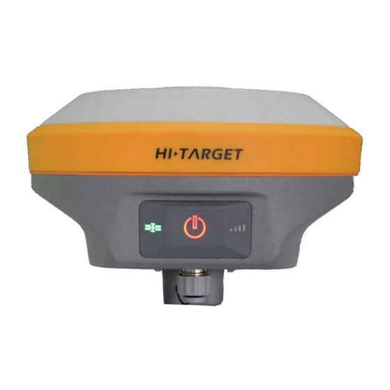
Page 13: Hardware Structure
4. Bottom Cover 5. Upper Cover V90 Plus mainly consists of three parts – the upper cover, bottom cover and the control panel. In the middle of the mainframe is the control panel, which contains a power button and three indicator lamps. - Page 14 V90 Plus GNSS RTK System Anti-wear buffer Figure 2-1-2 Upper Cover The U-type anti-wear buffer can effectively prevent the instrument from being scratched. The double-color model makes the structure clear and its appearance beautiful. Figure 2-1-3 Bottom...
- Page 15 V90 Plus GNSS RTK System Figure 2-1-4 Inside the battery compartment 1. The USB interface and protective plug ( which is used to both export data and upgrade firmware) 2. Speaker (operates the instrument and vocally broadcasts the status) 3. Metal buckle 4.
- Page 16 V90 Plus GNSS RTK System 11. Battery cover Note: 1. Please cover the 5-core socket with the plug when the product is not in use. 2. The speaker is likely to fall silent or go hoarse when water enters it, but it can recover when the speaker is dry again.
-
Page 17: Button
V90 Plus has an optimized and simplified design,with button operation and a more convenient and concise control panel. 1. Control panel Most of the V90 Plus Receiver’s settings and operations can be conducted by using the power button, which is below the control panel. - Page 18 V90 Plus GNSS RTK System Satellite lamp Signal lamp Figure 2-2-1 Control panel Power lamp 2. Button functions Table 2-2-1 Button functions Functions Detailed description Power-on Press power button for 1s to power-on. Power-off Long press the power button for more than 3s and less than 6s when the speaker makes the ding-dong sound.
-
Page 19: Led
V90 Plus GNSS RTK System when you hear the second ding-dong, and then release it. Mandatory power-off In the power-on state, long press the power button for more than 8s. 2.3 LED Table 2-3-1 LED description Lamp Status Description Power lamp... -
Page 20: Wi-Fi Password Setting
(insufficient storage space) 2.4 Wi-Fi password setting The V90 Plus receiver can be used as a Wi-Fi hotspot, which supports a user-defined password. (The factory default password is 12345678) Note: 1. See the attached list 1 for the Wi-Fi factory default password. -
Page 21: Static Data Collecting (By Button Operation)
2.5 Static data collecting (by button operation) The V90 Plus GNSS Receiver can collect static data. To operate it, see the instructions below. 1. Set up the receiver on a control point, making sure that you center and level it. - Page 22 V90 Plus GNSS RTK System Slant height - measure from the control point to the upper measurement benchmark. Figure 2-5-1 Static data collecting Note: 1. The instrument height should be measured from the control point to the upper part of the measurement benchmarker.
- Page 23 V90 Plus GNSS RTK System Figure 2-5-2 Benchmark 3. Record the point name, receiver S/N, receiver height and start time. 4. Press the power button to power-on the device and double-click the power button to set it to static collecting mode; then single-click the power button to confirm this.
-
Page 24: Web Management System
Note: Don’t move the tribrach or change the collecting set while the receiver is collecting data. V90 Plus’ default settings will not record Rinex format data. Users can change the relative settings by using the GNSS Receiver Manager software. Below is the GNSS Receiver Manager software interface. -
Page 25: Main Menu
V90 Plus GNSS RTK System configuration of the receiver. The device’s Wi-Fi name is the S/N, and you can connect it with the controller or phone (without a password), and then input the IP address, which is 192.168.20.1, into the browser to log into the WEB management system. - Page 26 V90 Plus GNSS RTK System Figure 2-6-3 Information Figure 2-6-4 Work mode Figure 2-6-5 File manager Figure 2-6-6 Firmware...
- Page 27 V90 Plus GNSS RTK System Figure 2-6-7 System Table 2-6-1 Menu description Main menu Sub-menu Description Information Device information Device model, version, registration information, etc. Position information Coordinates, satellite tracking, solution state, etc. Base information Coordinates and distance to the base.
-
Page 28: Information View
V90 Plus GNSS RTK System Firmware Upgrade Select and upgrade the firmware. Restore Restart the iRTK5 and update the OTA firmware. System Constellation Switches for the satellite tracking. 5-pin port The output settings of the 5-pin port. Radio Radio frequency settings. - Page 29 V90 Plus GNSS RTK System 2. Position information Includes the device position, satellites, solution state, local time, etc. Figure 2-6-9 Position info 3. Base information Includes the coordinates and distance of the base when it is in the rover mode.
- Page 30 V90 Plus GNSS RTK System Figure 2-6-10 Base info 4. Skyplot Includes the skyplot, which can switch to different constellations. Figure 2-6-11 Skyplot 5. Satellites list Shows information about the tracked satellites.
-
Page 31: Work Mode
V90 Plus GNSS RTK System Figure 2-6-12 Satellites list 2.6.3 Work mode 1. Rover Set up the data link and the rover’s parameters. Figure 2-6-13 Rover... - Page 32 V90 Plus GNSS RTK System 2. Base Set up the data link and parameters of the base and then get the point coordinates by averaging. Figure 2-6-14 Base 3. Static Set up the file name and the parameters of the static collection.
-
Page 33: File Management
V90 Plus GNSS RTK System Figure 2-6-15 Static 2.6.4 File management Static data: to show the static data files - it supports both the Download and Delete options. Figure 2-6-16 Static data 2.6.5 Firmware management 1. Upgrade Includes the specific device version information, and supports the firmware upgrade function. - Page 34 V90 Plus GNSS RTK System Figure 2-6-17 Upgrade 2. Restore Restart the iRTK5 and start the OTA firmware update. Figure 2-6-18 Restore...
-
Page 35: System Settings
V90 Plus GNSS RTK System 2.6.6 System settings 1. Constellation Switches of the satellite tracking. Figure 2-6-19 Constellation 2. 5 - Pin port Message type switches and output frequency adjustments. - Page 36 V90 Plus GNSS RTK System Figure 2-6-20 5-Pin port 3. Registration Includes the registration information, serial number, etc. Provides online registration. Figure 2-6-21 Registration...
-
Page 37: Firmware Update
V90 Plus GNSS RTK System 4. Others Static RINEX switch and adjust the volume of the device. Figure 2-6-22 Others 2.7 Firmware update The receiver uses a 3G network, and the host firmware can be automatically upgraded through the network (please refer to the Hi-Survey Road software guide). The user can also choose to do a manual upgrade by using the U-Disk. - Page 38 V90 Plus GNSS RTK System Figure 2-7-1 Update drive...
-
Page 39: Hi-Survey Road Software Quick Start
V90 Plus GNSS RTK System CHAPTER Hi-Survey Road Software Quick Start This Section Describes: Create a project Set the base Set the rover Parameter calculation Detail survey Stake out Data transfer Connect the controller to download data... -
Page 40: Create A Project
V90 Plus GNSS RTK System This section provides a Quick Start guide to operating of the V90 Plus with Hi-Survey Road. 3.1 Create a project 1. Open the Hi-Survey software, the software main interface is as follows: Figure 3-1-1 Main interface 2. - Page 41 V90 Plus GNSS RTK System 3. Project Settings: select the projection, set the source ellipsoid and projection parameters. Figure 3-1-4 Project settings Figure 3-1-5 Coordinate system Figure 3-1-6 Projection Figure 3-1-7 Datum...
-
Page 42: Set The Base
V90 Plus GNSS RTK System 3.2 Set the base Connect the device, click Device→Device Connection→Connect to select the base station number for Bluetooth pair connection. Figure 3-2-1 Device Figure 3-2-2 Connect Figure 3-2-3 Device number Figure 3-2-4 Disconnect... - Page 43 3. Click Data Link, select the data link type and enter the relevant parameters. (eg: when you use the Hi-Target server data to transfer operation, you need to set the parameters and select the built-in network; where the packet number and group number can be changed, the...
- Page 44 V90 Plus GNSS RTK System radio station to work, you should select the Internal UHF as the data link, and then select the radio channel). Radio mode is the traditional data link mode, and the built-in radio mode is taken as an example, to illustrate the introduction of radio station mode using simple steps.
- Page 45 V90 Plus GNSS RTK System Figure 3-2-8 Others 5. Check whether the host differential light is flashing once every second (2/sec in power-saving mode). When using the external radio station, the radio will flash once every second, if it is...
-
Page 46: Set The Rover
V90 Plus GNSS RTK System Figure 3-2-9 Set prompt 3.3 Set the rover Connect to the rover by Bluetooth, and confirm that the rover data link and other parameters are consistent with the base station. The setting of the rover station is the same as that of the base station. -
Page 47: Parameter Calculation
V90 Plus GNSS RTK System Figure 3-3-1 Set rover 3.4 Parameter calculation First set the control point library in Point Library→ Control Point to add control points, enter the name and the corresponding coordinates by manual input, real-time collecting, point library or map selection, and then click OK. - Page 48 V90 Plus GNSS RTK System Click Parameter Calculation, select Plane + Height Fitting type and Constant Vertical Offset in Height (the Height can be selected as Plane Fitting when there are three points above), and then add point pairs, select the point as the source point, enter the corresponding control point coordinate in the target point, then click Save.
-
Page 49: Detail Survey
V90 Plus GNSS RTK System generally smaller in the north and east, the rotation is about zero, the scale is between 0.9999 and 1.0000 (in general, the closer to 1, the better the scale is), the smaller the plane and elevation residual is, the better the result . -
Page 50: Data Transfer
V90 Plus GNSS RTK System There is a process to make the current point (triangle mark) close to the target point (round plus cross sign). When the staking-out circle turns red, it is finished and meets the precision parameters. In the process of staking-out, you can also collect detail points, by the Store on the interface or store keying on the hand-held. -
Page 51: Connect The Controller To Download Data
V90 Plus GNSS RTK System Figure 3-7-1 Data Transfer Figure 3-7-2 Export Figure 3-7-3 Custom Format 3.8 Connect the controller to download data Connect the hand-held to the computer with the USB data cable. Click USB Storage in the following dialogue box, then click OK in the dialog box when that appears. - Page 52 V90 Plus GNSS RTK System Find the path to export the data file on the hand-held (default: ZHD\Out), copy it to the computer, and then the RTK measure is finished. Figure 3-8-2 Exported data...
-
Page 53: Technical Specification
V90 Plus GNSS RTK System CHAPTER Technical Specification This Section Describes: Technical Parameters ... - Page 54 V90 Plus GNSS RTK System Table 4-1-1 Technical Parameters Configuration Detailed indicators GNSS Satellite signals Channels:220 Configuration BeiDou: B1, B2 GPS: L1C/A, L2C, L2E, L5 GLONASS: L1C/A, L1P, L2C/A (GLONASS M only), L2P GALILEO: L1 BOC, E5A, E5B, E5AltBOC SBAS: L1 C/A, L5...
- Page 55 V90 Plus GNSS RTK System Static and fast static Horizontal: 2.5mm + 0.5ppm RMS Vertical: 5mm + 0.5ppm RMS Post processing Horizontal: 8mm + 1ppm RMS kinematic (PPK/ Stop Vertical: 15mm + 1ppm RMS & Go) Initialization time: Typically 10 minutes for base while 5 minutes for rover;...
- Page 56 V90 Plus GNSS RTK System Transmitting speed: 9.6Kbps, 19.2Kbps Support most of radio communication protocol Working range: 3~5km typically, 8~10km optimal HI-TARGET external Frequency: 460MHz with 116 channels UHF radio Transmitting power: 5W, 10W, 20W, 30W adjustable Transmitting speed: Up to 19.2Kbps...
- Page 57 V90 Plus GNSS RTK System Power consumption ≤ 3.5W Environment Water/dustproof IP67 Free fall Designed to survive a 2m natural fall onto concrete Humidity 100%, condensing Operation temperature -40℃~+75℃ (-40℉~+167℉) Storage temperature -50℃~+85℃ (-58℉~+185℉) Note: 1 Developed under a License of the European Union and the European Space Agency.
Need help?
Do you have a question about the V90 Plus and is the answer not in the manual?
Questions and answers