
Subscribe to Our Youtube Channel
Related Manuals for Hi-Target V30


Summary of Contents for Hi-Target V30
- Page 1 V30 GNSS RTK System Manual V30 GNSS RTK System Manual Manual Revision Revision Revision Description Date Level V30 GNSS RTK System Feb.2014 Manual Hi-Target Surveying Instrument Co., Ltd. All Rights Reserved...
-
Page 2: Table Of Contents
V30 GNSS RTK System Manual Content Preface ..................1 Instruction ................2 Relative Information ............2 Your Suggestions ............... 2 Summary ................. 3 Introduction ................ 4 Product Features ..............5 Usage and Notes ..............5 Receiver Introduction ............7 Introduction ................ 8 Receiver Appearance ............ - Page 3 Diagram for rover working ..........48 Fast Operation Guide ............49 Static Collecting ..............53 Instruction ................ 54 The procedure of V30 static survey ......... 54 Download data with USB drive ........55 Management software operation for static survey ... 55 Technical Parameters ............58...
- Page 4 V30 GNSS RTK System Manual Receiver ................59 UHF Radio Communication ..........60 3G/GPRS Network Communication ....... 62 Ports ................. 62 Function Key and LED ............ 62 Intelligent Voice Module ..........62 Accuracy ................62 Physical Feature ............... 63 Environment ..............63 Ports and Main Accessory ...........
-
Page 5: Preface
V30 GNSS RTK System Manual C H A P T E R Preface Chapter Instruction ■ Instruction ■ Relative Information ■ Your Suggestions... -
Page 6: Instruction
Welcome to Hi-Target V30 Series GNSS RTK system manual. This manual is designed for V30 GNSS RTK system, and use V30 GNSS RTK as an example to explain the installation, setup, and usage of the GNSS RTK system. If you have used other GNSS RTK system before,... -
Page 7: Summary
V30 GNSS RTK System Manual C H A P T E R Summary Chapter Introduction ■ Introduction ■ Products Features ■ Usage and Notes... -
Page 8: Introduction
Meanwhile designed self-diagnosis function can automatically check the working status of all hardware and software of the V30 receiver while working, and arouse the problem part by its intelligent voice messenger in case of some problem. Data collection controller can be connected with receiver mainframe via Bluetooth or cable;... -
Page 9: Product Features
8. Adjustable to be single GNSS system or multi-GNSS system: GPS, GLONASS, GALILEO. Usage and Notes Although V30 receiver using chemical and impact resistance material, but necessary taking care and maintenance is still required for such a precise instrument. - Page 10 Summary Warning: The receiver must be used and stored in the specified temperature. More details please refer to Chapter 7: Technical Parameters. To ensure the quality of continuous tracking satellites and signals, surveying work should be in open air, while there should no any obstacle in space above 15°...
-
Page 11: Receiver Introduction
V30 GNSS RTK System Manual C H A P T E R Receiver Introduction Chapter Introduction ■ Introduction ■ Receiver Appearance ■ Control Panel ■ Upper Cover ■ Lower Cover ■ Communication Module ■ Battery ■ Environmental Requirement ■ Electric Interference... -
Page 12: Introduction
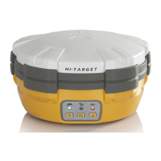
Receiver Introduction Introduction This Chapter mainly introduces V30 receiver appearance, buttons and indicator led and so on. Receiver Appearance Receiver Appearance mainly including 4 parts: upper cover, lower cover, guard collar and control panel, as Figure Upper Cover Guard Collar... -
Page 13: Control Panel
V30 GNSS RTK System Manual Control Panel Figure 3-2, in the middle of red frame of V30 receiver is control panel. And the control panel contains the F1 key (function key 1), F2 key (function key 2) and the power button, 3 indicator leds which are respectively satellite led, the status led (dual-color led ), the power led (dual-color led). -
Page 14: Upper Cover
Power Key: setting confirmation, automatically base setting and so on. Upper Cover Figure 3-3 indicates the upper cover of V30 receiver, the main function of which is anti-drop and anti-scratch. Raised Plate Raised Point Figure 3-3 Upper Cover ... -
Page 15: Lower Cover
V30 GNSS RTK System Manual Lower Cover As figure 3-4, lower cover of V30 includes communication module slot, battery groove, five-pin port, eight-pin port, loudspeaker and so on. Communication Module Connector Communication Module position Loudspeaker Joint Nut Eight-pin Port and Protection... -
Page 16: Communication Module
Receiver Introduction with external power supply Eight-pin Port: connect V30 receiver with computer, or controller for data download and delete Protection Plug: anti-dust and waterproof for socket SIM card slot: when choose GSM communication, install SIM card. -
Page 17: Battery
V30 GNSS RTK System Manual Protection Plug Difference Antenna Connector Figure 3-5 Communication Module 1 Module Connector Figure 3-6 Communication Module 2 Battery As figure 3-7, the appearance of 4400mAh lithium Battery... -
Page 18: Environmental Requirement
Cathode Figure 3-8 Battery Back Environmental Requirement Even though V30 receiver uses waterproof materials, maintaining in a dry environment is still helpful. In order to improve the stability, and duration of the receiver, please avoid exposing the receiver in extreme environments, such as: ... -
Page 19: Electrical Interference
V30 GNSS RTK System Manual Electrical Interference Do not place GNSS receiver around a strong power interference signal source, such as: Oil duct ( spark plug ) Television and computer monitor Generator Electric motor DC-AC power conversion equipment ... -
Page 20: General Operations
General Operations C H A P T E R General Operations Chapter Introduction ■ Introduction ■ Button Functions ■ Led Status Instructions ■ Turn On/Off Receiver ■ Static Data Storage ■ RTK Data Storage ■ Reset Receiver ■ Back to Original Settings ■... -
Page 21: Introduction
V30 GNSS RTK System Manual Introduction Most of the operations of V30 receiver can be done by the three buttons on the mainframe panel. Buttons on the panel: Status Led Power Led Satellite Led Function Button Power Button Function Button F2... -
Page 22: Button Functions
General Operations Super long pressing Pressing button more than 6 second Slow flash of led Flashing interval more than 0.5 second Fast flash of led Flashing interval less than 0.3 second Button functions Button Factions Introduction operations Then single click F1 to choose the receiver work mode among “base”, Double click F1 Work mode... - Page 23 V30 GNSS RTK System Manual Collection Long pressing Single press F2 to set collectioninterval interval to be 1s,5s,10s Static data Double click F2 to start collecting Double click F2 collection static data Then the receiver will speak out its current work mode, data link, radio...
- Page 24 General Operations speaks out “external, base”; at the same time the power led flashing times hints the power status For rover in external mode: receiver speaks out “external, rover”; at the same time the power led flashing times hints the power status For base in internal UHF: receiver speaks out “UHF, base, channel **, power *”;...
-
Page 25: Led Status Instructions
V30 GNSS RTK System Manual Led Status Instructions Instruction Power In normal voltage: internal battery voltage >7.6V, Always on (yellow) external battery voltage >12.6V In normal voltage: 7.2V<internal battery voltage Always on ≤7.6V, 11V<external battery voltage ≤12.6V Power Low power-pressure: inter≤7.2V,external≤11V... - Page 26 General Operations Always on More than 4 satellites tracked successfully Slow flash Loss satellites and try re-tracking Satellite led 1. mother board error resulting in no data output (green) while resetting receiver 2. mother board error resulting in no data output while in static mode Led displaying in different mode: 1.
- Page 27 V30 GNSS RTK System Manual no confirming within 10 seconds, the receiver will automatically confirm the current settings.): ● on ○ off Satellite led Status led Data link (green led) (green led of dual-color led) UHF/GSM/CMDA ● ○ module Internal ○...
- Page 28 General Operations 4. Radio Channel (must be in UHF mode. Long press F2 to enter radio channel setting. Then single press F1 to choose channel by minus 1; or long press F1 to choose channel by minus 10; or single click F2 by plus 1; or long press F2 by plus 10.
- Page 29 V30 GNSS RTK System Manual ○ ● ○ ● ○ ● ● ○ ● ○ ○ ○ ● ● ○ ● ○ ● ● ○ ○ ● ● ● ○ ● ● ● ● ○ ○ ○ ○ ○ ●...
- Page 30 General Operations 5. Elevation Angle (must be in static work mode. Long press F1 to enter elevation angle setting. Then single click F1 to choose elevation angle. After that single click power button to confirm. If no confirming within 10 seconds, the receiver will automatically confirm the current settings.): ●...
-
Page 31: Turn On/Off Receiver
The GNSS static data collected by V30 receiver will be stored in its memory, in *.GNS format. You can connect the V30 receiver with PC by USB port of Y cable and then just copy the static data into your PC. -
Page 32: Reset Receiver
Format Receiver Format V30 receiver by Hi-Target V30 Receiver Management Software: Connect V30 with PC by serial port of Y data cable Turn on V30 receiver Choose right serial port and open port After connecting successfully as figure 4-2: the S/N will be showed in the below ... -
Page 33: Power Supply System
V30 GNSS RTK System Manual Figure 4-2 Warning: Make sure all useful data has been copied to another place for spare, because all data will be deleted forever after this format. Power Supply System Assembly and Disassembly of Battery Cover Assembly: 1. - Page 34 General Operations Metal lock Fix slot Figure 4-3 2. Turn the metal lock by 90° to the panel side and press it to be ok. Figure 4-4...
- Page 35 V30 GNSS RTK System Manual Disassembly: 1. Pull the metal lock up and turn to the two ports direction by 90° Figure 4-5 2. Pull the metal lock to get off the battery cover Figure 4-6...
- Page 36 General Operations Install and Uninstall Battery Install: 1. Match with the in the battery slot to put in the battery. Open Figure 4-7 2. Insert battery towards “Close” end (see red arrow) to install it ok Open Close Figure 4-8...
- Page 37 V30 GNSS RTK System Manual Uninstall: Slide the battery towards to the “Open” end, and then pull out battery is ok. Open Figure 4-9 V30 Receiver Battery Name and Model Name Model 4400mAh lithium BL-4400 battery V30 lithium battery...
- Page 38 6V ~ 36V Power range If use external power supply for V30 by the eight-pin port and five-pin port on the mainframe, the power supply should be 6~36V with current no less than 500 mAh. When using both lithium battery and external battery, the receiver will check the power pressure of both batteries and choose the higher one.
- Page 39 V30 GNSS RTK System Manual Battery charging BL-4400 lithium battery must be charged in specified CL-4400 charger of Hi-Target for about 6 hours. The indicator led of the charger will be in red while charging, and then green when charging finished.
-
Page 40: Communication Module
3. After connecting battery with the charger, the “Charging” led becomes red. Warning: 1. Only using Hi-Target specified charger and do not put the battery into fire nor make it short circuit. 2. If heating, deformed, leaking, bad... - Page 41 V30 GNSS RTK System Manual Install and Uninstall Communication Modules Communication modules are radio module, and GPRS/3G module. Radio module Figure 4-12 Radio module Installation: 1. Put the module into the module slot.
- Page 42 General Operations Figure 4-14 2. There are 7 screws in the module. Please screw them down using the screw driver. Figure 4-15...
- Page 43 GM-42PV radio of 390MHz~430MHz, which are compatible with Trimble Leica, there are 32 channels for users’ choice. There are two methods to set the radio frequency: 1. Long press F2 on the V30 mainframe to set. 2. After connected with controller, using Hi-RTK software to set.
-
Page 44: Sim Card/ Usim Card
General Operations to this channel and start your work. SIM Card/ USIM Card Either SIM card or USIM card can be used in V30: WCDMA(ZHD/VRS) USIM Card GPRS(ZHD /VRS) GPRS(ZHD /VRS) SIM Card Card installation For built-in GPRS SIM card: 1. -
Page 45: Firmware
Note: 3G card can also be installed here. Firmware Firmware upgrading There are two kinds of upgrading for V30: 1. Mainframe upgrading. 2. Radio module upgrading. Except the difference of choosing upgrading device, all the other operations are the... - Page 46 General Operations Figure 4-18 Steps for upgrading: Connect V30 with PC by serial port of Y type data cable Turn on V30 receiver Choose the right serial port and open port After connecting successfully as figure 4-2: the S/N will be shown in the bottom Choose the “upgrade device”...
- Page 47 V30 GNSS RTK System Manual Warning: The firmware file must be with the postfix as *.098.htb, or the upgrading will be failed. Click “upgrade” and then the receiver will be turned off automatically, then start again and it will start upgrading.
-
Page 48: Configuration Of Fieldwork
Configuration of Fieldwork C H A P T E R Configuration of Fieldwork Chapter Introduction ■ Introduction ■ Diagram for base working ■ Diagram for rover working ■ Fast Operation Guide... -
Page 49: Introduction
In this section, the working program and Easy of Use for the base and rover of V30 GNSS RTK are introduced. According to the system of V30 GNSS RTK which is required by the customer, only the customer who buys the module can get the relative configuration of working program and the configuration of working program. - Page 50 Configuration of Fieldwork Base receiver mainframe UHF transmitting antenna Tribrach Extension rod Tripod Figure 5-2 working mode for base with built-in radio...
- Page 51 V30 GNSS RTK System Manual Transmitting antenna Base receiver mainframe External power External supply radio Tribrach Tribach Power supply Tripod connecting Tripod cable External radio connecting cable Radio antenna connecting with receiver cable Figure 5-3 working mode for base with external radio...
-
Page 52: Diagram For Rover Working
Configuration of Fieldwork Diagram for rover working Rover receiver mainframe Rover receiver mainframe Carbon receiving fiber antenna centering pole Controller Carbon Controller fiber centering pole Figure 5-4 U HF r o ver Figure5-5 GPRS/3G rover... -
Page 53: Fast Operation Guide
The other way is by using the management software. Connecting the receiver to PC with Y type cable, then open the management software of V30 receiver, choose the serial port and then open it. After the instrument is connected, do the settings through the management software of V30 receiver. - Page 54 Configuration of Fieldwork Figure 5-6 GPRS Setting Netw Communicat Setting Contents ork mode ing way GPRS/CDM Group ID, IP, port and APN The dialing function, input the phone number of base. Make sure that the SIM cards have opened the calling function CDMA/CD IP address, port, network operator (APN), VRS user name, pass word,...
- Page 55 V30 GNSS RTK System Manual Double click F1 with the voice prompt “base”, “rover” and “ static” to choose the working mode you need, press power button to confirm the setting. 2. Set UHF data link Double click F2, then choose UHF mode from UHF,GSM and external radio then click the power button to confirm.
- Page 56 Configuration of Fieldwork sequence. Base or rover mode with external data link. 1. Set base/rover: Double click F1 with the voice prompt “base”, “rover” and “ static” to choose the working mode you need, press power button to confirm the setting. 2.
-
Page 57: Static Collecting
V30 GNSS RTK System Manual C H A P T E R Static Collecting Chapter Introduction ■ Introduction ■ The procedure of V30 static survey ■ Download data with USB ■ Management software operation for Static Survey... -
Page 58: Instruction
The height of instrument should be defined from the controlling point of base centre to upper edge of marker line. The antenna radius of V30 receiver is 0.087 meter; the height of phase center is 0.065 meter. Instrument height... -
Page 59: Download Data With Usb Drive
Download data with USB drive The data of V30 receiver can be downloaded with USB drive, use the Y type data cable, connect one side to USB port of PC and the other side to the 8-pin jack of main frame. After connecting, you will see a folder named GNSS in the PC, the static data are here, you can copy the according files directly. - Page 60 Delete original data Delete and format the whole memory Read parameters Set parameters Refresh list Figure 6-2 Operating steps: 1. Connect Y type data cable to 8-pin port of V30 receiver and the series port of PC...
- Page 61 Static data post processing: The new post processing software of Hi-Target is Hi-Target Geomatics Office (HGO), use this software to do post processing. Please refer to “Hi-Target Geomatics Office Data Post Processing Software Manual” for detailed information of data...
-
Page 62: Technical Parameters
Technical Parameters C H A P T E R Technical Parameters Chapter Introduction ■ Introduction ■ Receiver ■ UHF Radio Communication ■ 3G/GPRS/CDMA/Internet Communication ■ Ports ■ Function Key and Indicator Led ■ Intelligent Voice Module ■ Accuracy ■ Physical Feature ■... -
Page 63: Introduction
V30 GNSS RTK System Manual Introduction Here we list out all Technical Parameters of V30 GNSS RTK SYSTEM. The Technical Parameters will be a little different according to your purchase order. Please make sure about your configuration then find out Technical Parameters correspondingly. -
Page 64: Uhf Radio Communication
GSOF UHF Radio Communication GM-46V Module ◎ Compatible with V8 and the other products of Hi-Target with transmitting or receiving radio in 460 MHz ◎ W ith difference transmit-receiver function and transmit power can be adjustable among 0.1w, 1w and 2w ◎... - Page 65 V30 GNSS RTK System Manual o Transparent EOT Timeout o Transparent EOC Character o Packet Switched o TRIMTALK 450S o TRIMMARK II/IIe o TRIMTALK 3 o TT450S o SATEL External PCC Radio ◎ Original import PCC radio ◎ Input power: DC 9~30 V ◎...
-
Page 66: 3G/Gprs Network Communication
Technical Parameters o TRIMTALK 3 o TT450S o SATEL 3G/GPRS Network Communication ◎ Default Configuration with built in GPRS Internet Communication, with optional of 3G Module. Ports ◎ 2 RS-232 serial ports ◎ 1 USB port ◎ 1 port for wireless blue-tooth communication ◎... -
Page 67: Physical Feature
V30 GNSS RTK System Manual ◎ RTK Accuracy: Horizontal: ± (10+1×10⁻⁶D) mm Vertical: ±(20+1×10⁻⁶D) mm Physical Feature ◎ W ith ARM 7 Core Control Chip, built-in 64 M Flash Memory ◎ Dimension: φ19.5cm×h10.4cm ◎ W eight: 1.3 kg( Incl. li-ion battery) ◎... -
Page 68: Ports And Main Accessory
Ports and Main Accessory C H A P T E R Ports and Main Accessory Chapter Introduction ■ Introduction ■ 5-pin Port and 8-pin Port ■ Differential Antenna ■ Y Style Data Cable... -
Page 69: Introduction
V30 GNSS RTK System Manual Introduction This Section will introduce the outlook and operation for the main ports and accessory of V30 GNSS RTK system. The Technical Parameters will be a little different according to your purchase order. Please make sure about your configuration then find out Technical Parameters correspondingly. - Page 70 GND Earth 2. Cable Insert Mark GC-1, GC-2 signal can work with the cable connect earth internal only. 3. All the round plug seats from Hi-Target name the pin by positive counterclockwise; round plug name the pin by welding face counterclockwise.
-
Page 71: Differential Antenna
V30 GNSS RTK System Manual Point: All above are for facing the main frame, it’s the face icon for the socket of bottom main frame ( The plug welding surface) Differential Antenna Figure 8-3 Differential Antenna Refer to Figure 8-3, the differential antenna is an essential... -
Page 72: Y Type Data Cable
Ports and Main Accessory Figure 8-4 Differential Antenna installation Warning: When install the differential antenna, make sure rotating the right bottom fixed nut of differential antenna, don’t grip the top parts of differential antenna, Otherwise, it will make poor connect and reduce the working distance. - Page 73 V30 GNSS RTK System Manual Eight-pin Port: to connect with the eight-pin port of V30 receiver USB Port: to connect with PC USB for data downloading from V30 Serial Port: to connect with PC serial port for V30 firmware upgrade, receiver settings, manage static data file, set radio parameters, etc.
-
Page 74: Regulatory Information
Regulatory Information C H A P T E R Regulatory Information Chapter Introduction ■ Notes... -
Page 75: Notes
V30 GNSS RTK System Manual Notes Warning: Changes or modifications to this unit not expressly approved by the party responsible for compliance could void the user’s authority to operate the equipment. NOTE: This equipment has been tested and found to comply with the limits for a Class B digital device, pursuant to Part 15 of the FCC Rules.
Need help?
Do you have a question about the V30 and is the answer not in the manual?
Questions and answers
How To Change china To English?