Table of Contents
Advertisement
Advertisement
Table of Contents

Related Manuals for Hi-Target V200


Summary of Contents for Hi-Target V200
- Page 1 V200 GNSS RTK System User Manual...
- Page 2 V200 GNSS System User Manual Manual Revision Revision Date Revision Level Description V200 GNSS RTK System July. 2021 User Manual...
- Page 3 V200 GNSS System User Manual V200 GNSS RTK System User Manual...
-
Page 4: Experience Requirement
Welcome to the Hi-Target V200 receiver. This introduction describes how to use this product. Experience requirement To help you use the Hi-Target series products better, Hi-Target suggests that you read the instructions carefully. If you are unfamiliar with the products, please refer to www.hi-target.com.cn... -
Page 5: Technology And Service
V200 GNSS System User Manual Technology and service If you have any technical issues, please call the Hi-Target technology department for help, and we will answer your question. Relevant information You can obtain this introduction by: Purchasing Hi-Target products: this manual is found in the instrument container and will help you to operate the instrument. -
Page 6: Table Of Contents
V200 GNSS System User Manual Contents Preface ..............................I Introduction ............................. I Experience requirement ..........................I Tips for safe use ............................. I Exclusions ............................... I Technology and service ......................... II Relevant information ..........................II Advice ..............................II Contents ..............................III Chapter 1 ............................... - Page 7 V200 GNSS System User Manual 2.5 Tilt survey ............................20 2.5.1 Calibration-free tilt survey ....................... 20 2.6 Firmware upgrade ........................21 2.6.1 Upgrade by USB cable ......................21 2.6.2 Upgrade by using the web management system ..............22 Chapter 3 .............................. 23 Technical specification ..........................
-
Page 8: Overview
V200 GNSS System User Manual Chapter 1 Overview This chapter contains: - Foreword - Features - Use and precautions... - Page 9 8 cm by 20 %. 5. Hi-Fix technology enables both continuous connectivity and quality results. 1.3 Use and precautions The V200 GNSS receiver is designed to have chemical and impact resistance, but precision instruments require careful use and maintenance. Notice: The receiver must be within the specified temperature range when it is used and stored.
-
Page 10: Product Introduction
V200 GNSS System User Manual Chapter 2 Product introduction This chapter contains: - Overall appearance - Button & LED - WEB management system - Static survey - Tilt survey - Firmware upgrade... -
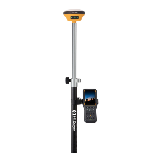
Page 11: Overall Appearance
V200 GNSS System User Manual 2.1 Overall appearance The product’s appearance is divided into three parts, including the upper cover, bottom cover and control panel. Figure 2-1-1 2.1.1 Upper cover Figure 2-1-2 2.1.2 Bottom cover The bottom cover includes the SMA antenna interface, Type-C USB interface. -
Page 12: Control Cover
V200 GNSS System User Manual Figure 2-1-3 1. SMA antenna interface 2. Connection screw 3. Speaker 4. Type-C USB interface ◇ SMA antenna interface: Connect the radio antenna while using the Internal UHF mode. ◇ Type-C USB interface: To upgrade the firmware and download static data. -
Page 13: Button & Led
V200 GNSS System User Manual 2.2 Button & LED 2.2.1 Button function Table 2-2-1 Button function description Function Description Power-on Long press the power button for 1 second. In the power-on state, long press the power button for more than 3 seconds but less Power-off than 6 seconds. -
Page 14: Web Management System
Satellite LED 2.3 WEB management system V200 has a built-in web management system that can be used to set the receiver's working mode, data output, as well as view receiver information and satellite information. The receiver’s Wi-Fi name is its S/N. You can connect it to a controller or phone (the default password is: 12345678) and then input the IP address 192.168.20.1 into the browser to log onto the web management system. - Page 15 V200 GNSS System User Manual Figure 2-3-3 Information Figure 2-3-4 Work mode Figure 2-3-5 File manager Figure 2-3-6 Firmware Figure 2-3-7 System...
-
Page 16: Information
V200 GNSS System User Manual Table 2-3-1 Menu description Main menu Sub-menu Description Device info Device model, version, registration info, etc. Position info Coordinates, satellite tracking, solution state, etc. Information Base info Coordinates and distance to the base Sky plot... - Page 17 V200 GNSS System User Manual...
- Page 18 V200 GNSS System User Manual 2. Position information Includes the device’s position, satellites, solution state, latency, PDOP and time, etc. Figure 2-3-9 Position information 3. Base information Includes the coordinates and distance of the base in the rover mode. Figure 2-3-10 Base information 4.
-
Page 19: Work Mode
V200 GNSS System User Manual Figure 2-3-11 Sky plot 5. Satellites list Shows the satellite’s tracked information. Figure 2-3-12 Satellites list 2.3.3 Work mode 1. Rover Set up the rover’s data link and parameters. The rover station data link includes: Internal UHF. -
Page 20: File Manager
V200 GNSS System User Manual Figure 2-3-14 Base 3. Static Set up the file name and parameters of the static collection. Note: After ticking Static Mode, you can only cancel it in the base rover setting interface. Figure 2-3-15 Static 2.3.4 File manager... -
Page 21: Firmware
V200 GNSS System User Manual Figure 2-3-16 Static data 2.3.5 Firmware 1. Upgrade Display specific device version information. Click Select, choose the upgrade package and then click Start. The receiver will automatically detect it and upgrade the firmware. Figure 2-3-17 Upgrade 2. -
Page 22: System
V200 GNSS System User Manual Figure 2-3-18 Restore 2.3.6 System 1. Constellation Switches of the satellite tracking. Figure 2-3-19 Constellation 2. Radio You can select the radio modulation protocol (HI-TARGET19200, HI-TARGET9600, TRIMTALK450S, TRIMTALK III, SATEL-3AS, SOUTH19200, SOUTH9600, CHC19200, CHC9600, TRANSEOT). - Page 23 V200 GNSS System User Manual Figure 2-3-20 Radio 3. Registration Display the registration information of the receiver. You can select the registration type, and then enter the corresponding code to register online. Figure 2-3-21 Registration 4. Reset Reset the motherboard.
-
Page 24: Static Survey
V200 GNSS System User Manual Figure 2-3-23 Others 2.4 Static survey Static survey is a kind of positioning survey, which is mainly used to establish various control networks. 2.4.1 Static settings There are two ways to set up the device to work in the static mode: 1. - Page 25 V200 GNSS System User Manual 3. Record the point name, S/N, receiver height and beginning time. 4. Press the power button to power-on and set up the static collecting mode. 5. Turn off the receiver after the static data is collected and record the turn-off time.
- Page 26 V200 GNSS System User Manual Figure 2-4-3 2. Download in the web management system The Wi-Fi name of the receiver is its S/N. You can connect it to a controller or phone (the default password is: 12345678) and then input the IP address 192.168.20.1 into the browser to log into the WEB management system.
-
Page 27: Tilt Survey
V200 GNSS System User Manual 2.5 Tilt survey 2.5.1 Calibration-free tilt survey Connect the receiver in the Hi-Survey Road software to open the Tilt Survey in the Survey → Surveying Configure → Data interface. Click the Tilt Survey icon and follow the prompt on the Hi- Survey Road interface to finish the initialization. -
Page 28: Firmware Upgrade
V200 GNSS System User Manual Notice: 1. Make sure the actual pole height is consistent with the set pole height before the tilt survey. 2. When turning on the Tilt Survey switch, you will need the initialization operation before normal use. -
Page 29: Upgrade By Using The Web Management System
V200 GNSS System User Manual Figure 2-6-1 2.6.2 Upgrade by using the web management system Copy the firmware to the controller or phone and use Wi-Fi to connect it to the receiver. The name of the Wi-Fi is the device’s S/N. Now, input 192.168.20.1 to log in, click Firmware upgrade - Select - File to choose the firmware, and then click start to upgrade it. -
Page 30: Chapter 3
V200 GNSS System User Manual Chapter 3 Technical specification This chapter contains: - Technical specification... - Page 31 V200 GNSS System User Manual 3.1 Technical parameters Table 3-1-1 Technical parameters Configuration Detailed Indicators Satellite signals tracked simultaneously GNSS configuration Output format ASCII: NMEA-0183, Binary data Positioning output 1~20Hz Static data format GNS and RINEX Message type CMR, RTCM3.0, RTCM3.2...
- Page 32 V200 GNSS System User Manual Protocol: HI-TARGET, TRIMTALK450S, TRIMMARK III, TRANSEOT, SATEL-3AS, CHC, SOUTH Internal UHF Channels: 116 totally, 100~115 configurable External antenna Max gain 5.0dBi User Button Power button*1 interface Notice : Recommend a separation distance of 0.31m or more should be maintained between this device and persons during device operation.
- Page 33 V200 GNSS System User Manual LED prompt light 3 LED lights, Satellite light, Data light, Power button WEB UI WEB website Internal WEB, Receiver settings, Status checking Radio antenna port 1, SMA port, connect the antenna Output Port 1, Type-C USB port, firmware upgrade and static data...
-
Page 34: Accessories And Interfaces
V200 GNSS System User Manual Chapter 4 Accessories and interfaces This chapter contains: - Data cable - Antenna - Battery & charger... -
Page 35: Data Cable
V200 GNSS System User Manual 4.1 Data cable Type-C cable: To connect the receiver to the PC for upgrading the firmware and downloading static data. Figure 4-1-1 Type-C cable 4.2 Antenna The UHF radio antenna is used in the Internal UHF mode. - Page 36 V200 GNSS System User Manual Figure 4-3-1 charger Notice: Please use this product’s standard charger to charge the receiver. We will not be responsible for any accidents that occur during the charging process or any damage to the instrument if you use other chargers instead.
- Page 37 V200 GNSS System User Manual Europe Importer: Address of Importer:...
- Page 38 § 15.19 Labelling requirements. This device complies with part 15 of the FCC Rules. Operation is subject to the following two conditions: (1) This device may not cause harmful interference, and (2) this device must accept any interference received, including interference that may cause undesired operation. §...
Need help?
Do you have a question about the V200 and is the answer not in the manual?
Questions and answers