
Related Manuals for Hi-Target V60


Summary of Contents for Hi-Target V60
- Page 1 V60 Getting Started V60 Getting Started Co., Ltd Hi-Target Surveying Instrument All Rights Reserved...
-
Page 2: Table Of Contents
V60 Getting Started Content 1. Introduction of hardware ------------------------------------------------------------------------------ 1 1.1 Hardware structure ---------------------------------------------------------------------------------- 2 1.2 Buttons operation and screen display ----------------------------------------------------------- 8 1.3 Descriptions of indicator lamp on the control panel --------------------------------------- 17 1.4 Static collection and data transmission ------------------------------------------------------- 18 2. - Page 3 6.2 Upgrade firmware -------------------------------------------------------------------------------- 132 6.3 Correction data transmitting issues ---------------------------------------------------------- 133 6.4 Internet accessing issue ------------------------------------------------------------------------ 136 6.5 Transceiver issue --------------------------------------------------------------------------------- 137 6.6 Signal descriptions of 5-core/8-core socket ------------------------------------------------ 137 6.7 Signal descriptions of V60 indicator lamp --------------------------------------------------- 138...
-
Page 4: Introduction Of Hardware
V60 Getting Started C C C C H H H H A A A A P P P P T T T T E E E E R R R R Introduction of hardware ■ Hardware structure ■ Buttons operation and screen display ■... -
Page 5: Hardware Structure
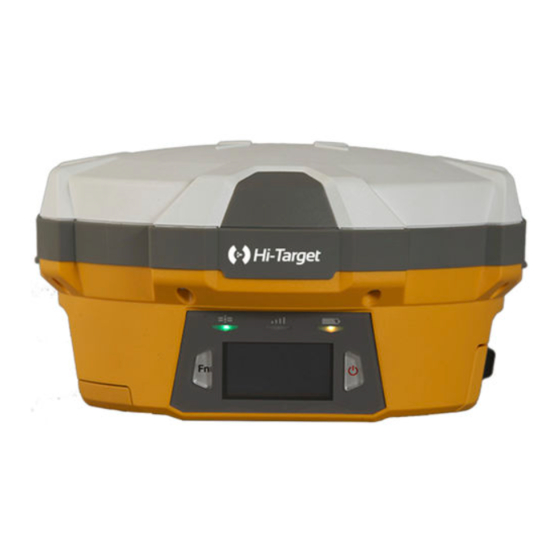
Introduction of hardware 1. Introduction of hardware 1.1 Hardware structure Hardware Schematic Diagram Upper Cover Guard Circle Bottom Cover Control Panel Fig.1.1-1 Control Panel There are FN button, Power button and three indicator lamps on the control panel .Three indicator lamps are satellite lamp (single green lamp), status lamp (bi-color lamp of red and green) and power lamp (bi-color lamp of red and green) from the left to the right. - Page 6 V60 Getting Started Upper Cover Anti-wear Buffer Fig.1.1-2 Anti-wear buffer: Anti-wear buffer can effective avoid the instrument from scratches. Bottom Cover Fig.1.1-3 1. 8-core socket and protective plug 2. 5-core socket and protective plug 3. Differential antenna port and protective plug: 4.
- Page 7 Introduction of hardware 3. Transceiver antenna port: Used to connect internal transceiver antenna for receiving and transmitting differential signal. Cautions: 1. when 8-core socket or 5-core socket is not in use, please cover them with the plug. 2. When water enters into the trumpet, it is likely that the trumpet is silent or hoarse.The voice can recover after the trumpet is dry.
- Page 8 V60 Getting Started 1. 5-core socket: It is also known as COM2/PW2, which is generally used to connect the receiver with external data chain or the external power supply. 2. 8-core socket: It is also known as COM1/USB/PW1, which is used to connect with computer, handheld controller and other equipment for downloading and deleting data.
- Page 9 Introduction of hardware Environmental requirements V60 receiver is designed by waterproof material but please try to keep its environment dry. In order to improve the stability and service life, please avoid the receiver from being exposed to extreme environment for use, for example: ◇Humid environment...
- Page 10 6V min. and 28V max. Scope of Power Supply V60 receiver can be supplied with the power by the external power supply of 8-core socket and 5-core socket at the bottom of receiver ,in which, once external power supply of 8-core socket is powered on, the receiver can power on automatically.
-
Page 11: Buttons Operation And Screen Display
3. If the service time of the battery is shortened obviously, please stop using the battery. It indicates that the battery has been aged; please replace it with new one. 1.2 Buttons operation and screen display 1. Control panel For Hi-Target V60 receiver, most settings and operations can be realized by two keys on the control panel. - Page 12 V60 Getting Started 2. LCD Buttons operation V60 GNSS RTK system can open/close the liquid crystal panel display by double clicking power button. High-definition LCD panel with two buttons complete the basic work demands of receiver , which can set three work modes of base, rover station and static state flexibly. Detailed descriptions of keys operation of control panel are as follows.
- Page 13 Introduction of hardware Operation Description Single-click Button operation time is less than 0.5 seconds Double-click Interval time for double-click is more than 0.2s but less than 1s. Long-time press Button operation time is more than 3s. Super long-time press Button operation time more than 6s. Slow flash The lamp is flash with frequency of more than 0.5s.
- Page 14 V60 Getting Started Single-click button to select, GSM data chain: input IP address single-click power button to serial port; grouping No. , and edit, and select "OK" after group No. Set GSM parameter edition to confirm. UHF (Internal transceiver): Select...
- Page 15 Introduction of hardware Static setting Cutoff angle of satellite:0 °- 30 ° Sampling interval: 1s, 2s, 5s, 10s, 15s, 30s Select '' '' single-click System information provide with the power button to return to current information of receiver, the previous menu. stellar map and system status, etc.
- Page 16 2. For GSM data chain interface of parameter setting, it can take effect only by setting Hi-Target server IP: 202.96.185.34; Port: 9000; Grouping number (7 bits); Group number (3 bits) on the panel.
- Page 17 Introduction of hardware Single-click Voice prompts the current work mode, data confirmation power button chain mode and radio power and channel; meanwhile, the power lamp indicates the battery capacity. Automatically Key Fn power button Firstly press Fn button, then press power button set the base for power on for power on and do not loosen Fn button until...
- Page 18 V60 Getting Started Table Descriptions of SIM card/USIM card USIM card GPRS(ZHD/VRS) SIM card GPRS(ZHD/VRS) Installation procedure of SIM card: (1) Demount the battery cover and remove the battery to make the SIM card slot exposed. SIM slot SD slot Fig.1.2-3...
- Page 19 Introduction of hardware 5.Transceiver UHF transceiver Internal transmitter-receiver (Standard configuration) Band of transceiver: 450-470MHz, 116 channels can be switched over flexibly. Transmitted power can be adjusted among 1W, 2W and 5W. Transmission rate: 19.2Kbps and 9.6Kbps, which are available for adjustment. PCC XDL transceiver module (Optional purchasing) Transceiver frequency: 403MHz-473MHz, frequency table can be modified by yourself.
-
Page 20: Descriptions Of Indicator Lamp On The Control Panel
V60 Getting Started (3) Set data chain: → → Single-click power button for confirmation when the steps are finished. 1.3 Descriptions of indicator lamp on the control panel Display state of indicator lamp under different setting mode: 1. Work mode (Double-click Fn button to enter into the work setting mode, then single-click Fn button to make mode selection and click power button for confirmation. -
Page 21: Static Collection And Data Transmission
◇ Height between the bottom of receiver and antenna phase center :94.2mm ◇ Height between measurement line of receiver height and antenna phase center:39.3mm *If the antenna parameter certificated by NGS is needed, please view http: //www.ngs.noaa.gov/ANTCAL/Antennas.jsp?manu=HI-Target 5-core socket and 8-core socket Phase center 39.3... - Page 22 V60 Getting Started 4. Record point name, instrument No. height of instrument, time of beginning observation. 5. Power on, set the receiver to be static measurement mode according to the following button operations: (1) Set work mode: Single-click Fn button, it shows as follows from left to right under the RTK mode: data chain, difference parameter, work mode and system information.
- Page 23 Introduction of hardware Fig.1.4-2 The procedure of modifying the point name and antenna height of the downloaded static file as follows: 1. Select *GNS static file and double-click the mouse. 2. After popup of dialog box of "File Editor", modify the point name and inputting antenna height and click [OK].
- Page 24 V60 Getting Started 6. Data deleting. Select the data required to be deleted and click Delete to delete the selected files. 7. Set collection interval and cutoff angle of satellite: Input the value to be changed and click to set the parameter.
-
Page 25: Handheld Controller And Application
Handheld controller and application C C C C H H H H A A A A P P P P T T T T E E E E R R R R Handheld controller and application ■ Introduction to the handheld controller ■... -
Page 26: Introduction To The Handheld Controller
V60 Getting Started Introduction to the handheld controller ◇ Industrial design, IP68 design, resistance to fall from the height of 1.2 m and adaption of all kinds of complicated working environments outdoor ◇ 640*480 Highlighting LCD with 3.7 inches can be readable normally under strong sunlight ◇... - Page 27 Handheld controller and application Touch screen Keyboard Fig.2- 1 Touch screen: Multipoint capacitive touch screen with touch pen, which supports Chinese and English input. Keyboard: Photograph, direction control, switch between Chinese and English, data collection, volume control, power on, power off and other functions. Microphone: Internal microphone can be used for field collection of voice message.
- Page 28 V60 Getting Started Camera Trumpet Battery cover Belt t Fig.2- 2 Camera: Used for field collection of image information. Battery cover: Internal removable lithium battery. Belt: Connect the belt to prevent sliding down. Trumpet: Conduct real-time voice broadcast for the instrument operation and status.
-
Page 29: Handheld Controller Accessories
Handheld controller and application Side of handheld controller Waterproof & dustproof rubber cover Audio port Mini USB Fig.2- 3 Mini USB: Used for connecting USB data line and iHand20 handheld controller. Audio port: Used for connecting headphone cable and iHand20 handheld controller. Warnings: In case of not using audio port or Mini USB, please close the rubber cover so as to achieving waterproof and dustproof. - Page 30 V60 Getting Started Battery Lithium battery: 3.7V /6300mAh Fig.2- 5 Data line Fig.2- 6 USB data line: ◇ Connect to the USB port of computer, and used for download of data ◇ Connect to the USB port of charger and used for charging handheld controller Touch pen Fig.2- 7...
-
Page 31: Operation Of Handheld Controller
Operation of handheld controller Keyboard Most settings and operations of Hi-Target iHand20 handheld controller can be completed by the touch pen, and commonly used operations can be completed by keyboard. Appearance and functions of keyboard are introduced briefly as follows. - Page 32 V60 Getting Started Button APP: Quick start of Hi-Survey software, press button APP for a long time for the Road popup, then select "Hi-Survey Road" and click [Ok]. And the software selected this time can be started quickly only by pressing key APP next time.
- Page 33 Handheld controller and application Fig.2- 10 Collect button: Collect data by manual operation. Camera button: Press it for a short time to enter into photograph interface; Press it for 3s on the non-camera interface to start up/shut down flashlight function. Screenshot function: Press "VOL-"...
-
Page 34: Installation Of Sim Card
V60 Getting Started Charging: It shall be charged with special charger within a certain temperature range and a certain charging time. Specific usage methods and requirements: It shall be charged by special charger with standard configuration of iHand20 within the temperature range of 0℃-40℃.For the first usage, there is a certain electric quantity in the battery generally. - Page 35 Handheld controller and application Installation procedures of SIM card 1. Unload the battery cover and remove the battery to make the SIM card slot expose. SIM1 SIM2 Fig.2- 11 2. Put SIM card in the card base and insert it into the slot without loosening with the front (the side with metal contact) facing downward.
-
Page 36: Power On And Power Off Operation
V60 Getting Started Fig.2- 14 4. Push upward with the tip of the finger resisting the sheet metal of slot until it is stuck without looseness. Power on and power off operation Under the power off status, press the power button for 3s to power on;... -
Page 37: Data Download
Handheld controller and application Fig.2- 15 Data download Connect handheld controller to computer 1. Connect handheld controller to computer by supporting USB data line, and pull down the notice column and click USB computer connection [open USB storage]. Fig.2- 16... - Page 38 V60 Getting Started 2. If it is required to synchronously operate handheld controller or install and use third-party software to debug data on the computer, "USB debugging" function shall be ticked. Turn on the handheld controller, and click [System Settings]→[Developer options ]→[USB debugging] on the desktop menu.
- Page 39 Handheld controller and application [USB debugging] 3. In the popup debugging window, click [OK] to complete the connection between handheld controller and computer. 4 In the computer, file operations between handheld controller and computer can be conducted by [Portable Devices]. Fig.2- 17...
-
Page 40: Hi-Survey
V60 Getting Started C C C C H H H H A A A A P P P P T T T T E E E E R R R R Hi-Survey ■ Creat a project ■ Measurement and collection ■... -
Page 41: Creat A Project
Hi-Survey 3. Hi-Survey 3.1 Setting 1. New project After new project is built before the measurement, the collected data will be saved in the project. When building new project, relevant setting needs to be conducted, for example, setting of project information, and coordinate system, etc.. - Page 42 V60 Getting Started "Project Info": New project can be built and the existing project can be opened or deleted. Fig.3-2 (3) Input project name in "Name" box->click "OK"; Input project name in "Name" box->click "OK"; (Note: The name of new project shall...
- Page 43 Hi-Survey 2. Bluetooth connection Receiver is connected with handheld controller by bluetooth, therefore, it is necessary to do this step before the operation. If conducting RTK under the mode of UHF (transceiver), two sets of receiver bluetooth shall be configured at least (one for base and one for rover). (1) Device ->Blue Tooth->Connect->Search device;...
- Page 44 V60 Getting Started Click "Connect" Click "Search device" to search the bluetooth device nearby.
- Page 45 Hi-Survey (2) Select S/N code of the device to be connected->input bluetooth PIN"1234"; Configuration PIN of buletooth:1234 Click "OK" to connect (May take a few seconds)
- Page 46 V60 Getting Started After connection, the interface will display current work mode, firmware version, firmware version of GPS main -board and log-on message, etc... (3) Use the same method to connect with other GPS receiver (Such as 10211158). Connection Process...
- Page 47 Hi-Survey Connected 3. Set coordinate system For measurement, coordinate system must be configured, because it is related to the accuracy of coordinate.There are two methods to set the coordinate system. A. build a new coordinate system, including Ellipsoid projection and Ellipsoid transformation parameters, etc. B&C. Import existing coordinate system.
- Page 48 V60 Getting Started Click Project Settings:Including settings of project and coordinate system information Enter settings interface...
- Page 49 Hi-Survey A .Build a coordinate system: Projection->Ellipsoid switchover->Elevation fitting (1) Click "Projection"-> ->User Defined Click to enter into the setting interface. User Defined:User can conduct the setting according to his own local parameter.
- Page 50 V60 Getting Started (2) Input projection information (Input ellipsoid information according to local actual situation) Click "System" to input name of coordinate system->"Projection" to select projection mode and take "Transverse Mercator" for example. System: Define the name of coordinate system...
- Page 51 Hi-Survey (3) Click "Datum", set Source Ellipsoid and Local Ellipsoid, Click "Datum", set Source Ellipsoid and Local Ellipsoid, but the ellipsoid information is determined by local and project requirement and must be accurate. Source Ellipsoid: Optional, commonly use WGS84...
- Page 52 V60 Getting Started Local Ellipsoid: (optional) determined according to specific requirements; Note: The parameters are different according to different ellipsoid. (4) Select switchover model: click "Model"; take Bursa-Wolf (Boolean Sally seven parameters) for example. Click "Model" to select switchover mode...
- Page 53 Hi-Survey Take Bursa-Wolf for example Input switchover parameters DX: X Translation DY: Y Translation DZ : Z Translation RX: X Rotation RY: Y Rotation RZ: Z Rotation K (ppm): Scale factor. All the above information shall be confirmed locally. (5) Height fitting (It can be skipped over if the fitting is not required) Height->select elevation fitting mode;...
- Page 54 V60 Getting Started Click Height->Model Including modes of Geometric Surface, TGO, Grid and Free Survey.
- Page 55 Hi-Survey File:Add file->Click "save" (6) Click "Save" to complete settings and saving of coordinate system. B. Add existing coordinate system files(user-defined) 1) Click "dam" ->Select .dam File; Click to return the parent directory. Path: SD Card ->ZHD->Geo Path ->select .dam file (take the addition of DD. dam for example) ->click "OK". Click "dam"...
- Page 56 V60 Getting Started Select dam File; click Path is: SD Card ->ZHD->Geo Path Note: Till seeing the SD card catalogue, Click" " to return to the parent directory.
- Page 57 Hi-Survey Select coordinate system files, with the suffix of .dam. And click "OK" to complete the selection. (2) Return " "- > select .dam file->click "Apply"-> select "OK"; Return " "-> select .dam file...
- Page 58 V60 Getting Started Click "Apply"-> select "OK"; C. Add coordinate system files(Hi-Survey software BYO) The software adds many coordinate systems all over the world intelligently for reference and selection. (1) Return" "->"Predefined" Return" "...
- Page 59 Hi-Survey Click "Predefined" (2) Select the continent located, take Eastern Asia for example; Select continents and countries in the region where you are located. For example, select the Eastern Asia.
- Page 60 V60 Getting Started (3)Add corresponding coordinate system file into "Predefined List" ->select the file->click "Apply" to apply it to current project. Select corresponding coordinated system and add it into the list. Select corresponding coordinated system and add it into the list.
- Page 61 Hi-Survey Click "OK" to complete the application 4. Set the base Set the base,setting parameter of base after bluetooth connection. Including: coordinate of base, communication mode, difference scheme, etc... Base is responsible for transmitting difference to the rover so as to conduct real-time difference. The base can be set by handheld controller only when the device bluetooth has been connected.
- Page 62 V60 Getting Started Open software "Main interface" ->Device Confirm current connected GPS receiver (take 11001649 for example)
- Page 63 Hi-Survey (2) For example: Set 11001649 as Base; For example: Set 11001649 as Base; (3) Select "type of antenna" ->input "target height"(Target H) PS: Select type of antenna according to the type of receiver, V60forexample. Antenna: The system can be default to select corresponding type of antenna (but is can be selected autonomously);...
- Page 64 V60 Getting Started (4) There are three methods to set "coordinate of base": A. Input with known point. B. Get by average. C. Select from the collection point library; A. Input with known point. 1) Ensure accuracy of coordinate of base;...
- Page 65 Hi-Survey Click" " Click "OK" to obtain position of base.
- Page 66 V60 Getting Started C. Obtain from point library 1) Click " " Click" " In the point library, there are "original data" and "control point" data, etc. for optional.
- Page 67 Hi-Survey (5) Set data chain, including A. "Internal UHF", B."Internal GSM" (Omitted), C."External Device" Click "Datalink" There are 5 kinds of data chain, which are Internal UHF, Internal GSM, External Device and External Network (3G).
- Page 68 V60 Getting Started A."Internal UHF" 1) Data link->select "Internal UHF" 2) Set "Chanel", "Sky Baud rate", "Power", etc. Datalink: Internal UHF Channel: 0-116 channels (DDTR-type instrument transceiver) for optional, 0-32 channels (PCC transceiver) Transceiver type and channel of base and rover must be same.
- Page 69 Hi-Survey 4) Click "Set" to complete the setting of base Click "Set" to complete the setting of base If the setting of base is completed, the software prompts "setting of rover".
- Page 70 V60 Getting Started C."External Device" 1) Datalink-> select "External Device"; When base data chain selects "External Device", channel of transceiver will be determined by the external device. 2) Other setting (including difference scheme, elevation cutoff angle) method is the same with the Internal UHF method;...
- Page 71 Hi-Survey 3) Click "Set" to complete the setting of base. 5. Set the rover (1) After completing setting of base, enter into "setting of rover" ->select "Yes"->click "Connect" (take 10211158 for example) to set the rover. Click "Yes" to jump to setting of rover Click "Connect"...
- Page 72 V60 Getting Started (2) Click "Connect" and select receiver equipped with bluetooth (take 10211158 for example) If the device has not been equipped with the bluetooth, please refer to above "Bluetooth connection" method for configuration. The connected instrument can display fuselage number (Such as: 10211158) (3) Set rover "Datalink", including "Channel"...
- Page 73 Hi-Survey Datalink: Internal UHF Conformity with base (take 6 for example) Conformity with base (take 19200 for example) (4) When base communicates with the rover successfully and differential lamp (middle lamp) in both base and rover flash red. 6. Floating box Common Satellites-Satellites Solution Receiver power...
- Page 74 V60 Getting Started "Correction latency": Refers to calculating time after rover receives the signal from base. "PDOP value": Intensity factor of space geometry where the satellite is distributed. Generally, the better the satellite distribution is, the smaller the PDOP value is. Generally, the value is less than 3 as the more ideal state.
- Page 75 Hi-Survey (2) Stellar map ◇ Distribution situation of projection position of satellite can be viewed. Roundness refers to GPS satellite and SBAS satellite, square refers to GLONASS and BDS satellite. GPS: Prn value is 1-32; GLONASS: Prn value is 65-96; BDS: Prn value is 161-197. Satellite view ◇...
- Page 76 V60 Getting Started Input elevation cutoff angle in "Elevation (。)" and click "Set" to set the elevation cutoff angle of receiving satellite. ◇ Click "Status", and give the color according to L1 carrier signal to noise ratio of satellite: orange <=15, yellow<=35, green>35As shown in the following figure:...
-
Page 77: Measurement And Collection
Hi-Survey (3) Signal-to-noise ratio figure of satellite: Prn refers to number of satellite; Azi refers to azimuth angle of satellite; Ele refers to satellite elevation, L1 refers to signal to noise ratio of L1, and L2 refers to signal to noise ratio of L2. Click "SAT Info", and Prn refers to number of satellite, L1 refers to signal to noise ratio of L1, L2 refers... - Page 78 V60 Getting Started The steps entering into the collection interface: Survey->Detail Survey; Click "Survey"->Detail Survey Detail Survey interface...
- Page 79 Hi-Survey 1.Single-point collection Single-point collection means collecting the data of each point by manual operation. (1) Click " "->" " Click " " Click " "...
- Page 80 V60 Getting Started (2) Input information of collection point, including point name, target height (the first point needs to be measured and the next points can be defaulted) and point position description (non-input optional).Click "OK" to complete the collection of the point.
- Page 81 Hi-Survey 2. Average collection That is averaging for the multi-measurement value of coordinate for each point. (1) Click " " to collect -> click "OK" Click " " After the average collection, click "OK"...
- Page 82 V60 Getting Started (2) Input information of point name -> click "OK" for saving; Input information of point name (Name), target height (Target H), description (Desc) and station After inputting, click "OK" At the moment, the point will be saved...
- Page 83 Hi-Survey (3) Cautions: Setting method of average collection: 1) Click "Config" in the average collection interface; Click "Config" to enter into average collection setting interface. 2) Times of "Average" ≥10; Available to set the average times...
- Page 84 V60 Getting Started 3. Automatic collection Automatically record measurement point according to the configured record condition. (1) Click " " Click" "to start automatic collection (2) Collection setting, including sampling interval (time or distance), point name and number, etc. (user-defined available)
- Page 85 Hi-Survey (3) Click "OK" to start collection Click "OK" to start collection The collected point can be stored automatically.
- Page 86 V60 Getting Started (4) Click " " to stop automatic collection; Click " " to stop automatic collection; 4. View all collected points (1) Click "Project->Points" in the software main interface Click "Project"->Points...
-
Page 87: Export Of Data Achievement
Hi-Survey Inquire the point library 3.3 Export of data achievement Data achievement export supports the following format: *.txt, *.CSV, *.dxf, (shp File)*.shp and (Excel File)*.csv. The export procedures are as follows. (1) Project->Data Transfer... - Page 88 V60 Getting Started Click" Data Transfer" (2) Select "Export". Select "Export"...
- Page 89 Hi-Survey (3) Define name of file exported -> select saving path; Input name of file->select output format->select saving path Export format of file includes(8kinds): User-defined(*.txt), User-defined(*.CSV), dxfFile(*.dxf), shpFile(*.shp), Excel File(*.CSV), South cass7.0(*.dat), Scsg2000(*.dat), PREGEO(*.dat).
- Page 90 V60 Getting Started (4) Select file format (take *.dxf for example) ->click "OK" to complete data export.
-
Page 91: Stake Out
Hi-Survey 3.4 staking out lofting, also called staking-out, refers to mark the plane position and elevation of buildings and structures planned and designed on the design drawing on the ground with certain measuring method according to required precision as the basis of construction. Confirm coordinate system of staking out coordinate file before staking out and if coordinate system is inconsistent, the staking out will fail. - Page 92 V60 Getting Started Enter into "Stake Point" interface 2. Click" "(enter into point selection interface) Click ''...
- Page 93 Hi-Survey Enter into stake point selection interface 2. This step has three point selection methods (Choose either), namely, A. Input coordinate; B. Select from coordinate library; C. Select from graph. A. Directly input coordinate 1) Input "Name"->Input NEZ coordinate->Click "OK" Input the point’s name and coordinate, tick "Save to Stake Pts Lib "to save the coordinate of input...
- Page 94 V60 Getting Started 2) Add the input coordinate point to "Stake points list"->Click "OK" to start stake. Start staking-out Stake interface Backward: Southward Towards the Right: Eastward Delta H: Altitude difference between stake coordinate and actual position Name : name of stake point σ: Relative precision...
- Page 95 Hi-Survey B. Select from coordinate library; 1) Input keyword of point name ->click " "->Coordinate point->select coordinate point; Input keyword of point name (look up keyword of point name) Click " " to jump into point library Jump into point library and select coordinate point.
- Page 96 V60 Getting Started 2) Tick Save to stake Pts Lib->Click "ok" Tick Save to stake Pts Lib->click "ok", add the coordinate point from the point library to the stake point library. 3) Input keyword->Click " " of point name in "Name"...
- Page 97 Hi-Survey Inquire result, select the required point and click "OK" to start stake. 4) Start staking-out Start staking-out...
- Page 98 V60 Getting Started Stake interface(indicate position of target point) Backward: Southward Towards the Right: Eastward Delta H: Altitude difference between stake coordinate and actual position Name : name of stake point σ: Relative precision HD: Horizontal Distance C.Select from graph;...
- Page 99 Hi-Survey Select stake point on Map 2) Click "OK" to start staking-out Start staking-out...
- Page 100 V60 Getting Started Stake interface (indicate position of target point) Backward: Southward Towards the Right: Eastward Delta H: Altitude difference between stake coordinate and actual position Name: name of stake point σ: Relative precision HD: Horizontal Distance ●Stake line 1. Click "Survey"->"Stake Line"->Click"...
- Page 101 Hi-Survey Click " " to enter into the stake line interface 2. Click " "->Click "Add" Click " "...
- Page 102 V60 Getting Started Click "Add" 3. Define straight line: Line There are 2 methods to define the straight line (select one according to situation), namely, A. "2Points to define the line" and B. "one point + azimuth angle".
- Page 103 Hi-Survey A. "2Points to define the line" 1) Select "2Points"->Input "name of line" ->Select "Start Point" and "End Point" ->Click "OK"; Tick "2Points" to define the straight line; Line name: Define the straight name; "2Points to define the straight line" need two elements of "Start Point"...
- Page 104 V60 Getting Started 2) At the moment, the straight line is added successfully, which also can be edited and deleted, etc. The added straight line can be viewed in the interface. The operation, such as edition and delete, can be conducted by selecting...
- Page 105 Hi-Survey B. "one point + azimuth angle" 1) Click "Add"->line->"Point + Azi" Click "Add"->line Tick "Point + Azi"...
- Page 106 V60 Getting Started 2) Select "Start point"->Input "Azi"->Click "Length" to input length of stake line->Click "OK" to complete the addition of straight line; Input the name of straight line and add coordinate and azimuth angle of "initial point". Only need extract the coordinate of...
- Page 107 Hi-Survey If added successfully, the added straight line can be displayed. 3.Start to stake after adding the stake straight line successfully. (1)Click " "->click "Milestone" to input milestone of point to be staked->click "OK" to enter into the stake interface. Cautions: Where the milestone and offset can be accumulated automatically according to the increment.
- Page 108 V60 Getting Started Stake direction: Prompt direction of target location Station of current stake: Refers to current milestone of stake (2)Click " " again to enter into next point station in which station and offset can be accumulated automatically based on increase.
- Page 109 Hi-Survey Under "Project" of the main interface>Data Transfer; 2) Select Stake Point->Import; Tick "Import" 3) Select "Dxf" file to be imported -> click "OK"...
- Page 110 V60 Getting Started Select "Dxf" file to be imported -> click "OK" 4) Click "Blank" part->select import format, such as (Name,N,E,Z, etc.), and click "OK" to complete the import. 2.Return to the stake interface and make stake using the same methods as that of stake line.
-
Page 111: Quick Guide Of Survce
Quick Guide of SurvCE C C C C H H H H A A A A P P P P T T T T E E E E R R R R Quick Guide of SurvCE... - Page 112 V60 Getting Started 4.Quick Guide of SurvCE ●Establish a new project 1.Open "SurvCE" software Single-click "SurvCE" Software loading (It is possible to take several seconds.)
- Page 113 Quick Guide of SurvCE 2.Select "Select New / Existing Job"->Input "file name" ->Click" ". Tick Continue Last Job and then the last project is defaulted to be opened. Select "Select New/Existing Job" to jump for selecting to open existing project or newly established project. Input project name...
- Page 114 V60 Getting Started 3.After project establishment, enter into "setting" in the coordinate system. There are two ways: A. User-defined coordinate system; B. Import existing coordinate system. A.User-defined coordinate system; 1)"System"-> Edit Projection List -> Add User Defined; Click "System"->Edit Projection List Add User Defined: add user-defined coordinate system.
- Page 115 Quick Guide of SurvCE 2) Input information of coordinate ->click" " Information of coordinate system: Including name of system (user-defined named), projection and measuring scale (Scale Factor). B. Import existing coordinate system. 1) Click "Add Predefined"->Select coordinate system->Click" "to complete the addition of coordinate system Click "Add Predefined"...
- Page 116 V60 Getting Started Click " " to complete the addition of coordinate system 4.Connect instrument and set Base The connection between handheld controller and receiver is also completed by bluetooth. 1) Click "Equip"->GPS Base Click "Equip"->GPS Base...
- Page 117 Quick Guide of SurvCE Interface of GPS Base setting: Manufacturer: Select "Hi-Target" Model (optional): Select corresponding model Model drop-down box for selection...
- Page 118 V60 Getting Started 3) Click "Comms "->Type: Bluetooth->click" "->Find Device- Click "Comms" -> Type and select Bluetooth Click" "->Find Device (Search for bluetooth device)
- Page 119 Quick Guide of SurvCE 4) Select instrument as "Base">Set Device PIN>click " ", at the moment, the bluetooth connection is successful. Select S/N of instrument as "Base", click Set Device PIN...
- Page 120 V60 Getting Started Input "1234" Click " " to complete the connection...
- Page 121 Quick Guide of SurvCE 3) Click "RTK" to configure base (Take built-in UHF for example) ->set difference scheme-> , configure power, transceiver channel and air Baud rate (Base shall be in conformity with Rover) ->click " " to save the setting.
- Page 122 V60 Getting Started Click enter into transceiver setting Power: Low, medium and high for optional Channel:1-116(DDTR domestic transceiver) 1-32 (PCC imported transceiver) Base is in conformity with the rover Air Baud rate Base is in conformity with the rover When the setting is complete, click"...
- Page 123 Quick Guide of SurvCE Click "Read From GPS" Average setting "By Number" or "By Time in min" for optional...
- Page 124 V60 Getting Started Average beginning (available to stop or cancel smooth ) Click "Yes" for completion At the moment, the setting for the base is completed and middle lamp of base begins to flash and the difference is transmitted.
- Page 125 1) Click "Equip"->GPS Rover-> select Man facture and Model; Click "Equip" and select "GPS Rover" Interface of GPS Rover setting Manufacturer: Select "Hi-Target" Model (Optional)Select corresponding model 2) Configure the bluetooth (with the same method as Base method) > -> Find Device ->Set...
- Page 126 V60 Getting Started Click "Comms" Type: Select "Bluetooth" Click " " Click "Find Device" to look for bluetooth device 3) Select connected device (for example: 10214309 is rover) -> click " ", and the bluetooth connection is successful.
- Page 127 Quick Guide of SurvCE Select connected device (For example,10214309 is rover) click" " At the same time, the bluetooth connection is successful. 4) Click "RTK" setting (difference scheme, channel and air Baud rate shall be in conformity with those of base) and click " "...
- Page 128 V60 Getting Started Click "RTK" to enter into RTK setting interface(Take UHF for example); Select "Internal UHF" Including format of RTCM, sCMRx, and RTCM3.0, etc...(The base shall be in conformity with the rover.) Click to enter into the transceiver setting interface.
- Page 129 Quick Guide of SurvCE Power: Optional Channel: 1-116 (Domestic transceiver) 1-32 (PCC imported transceiver) Air Baud rate Conformity with base Click to complete setting of rover...
- Page 130 V60 Getting Started 6. Click "Store Points" to enter into measurement interface Click "Store Points" to enter into measurement interface...
-
Page 131: Technical Parameters
Technical parameters C C C C H H H H A A A A P P P P T T T T E E E E R R R R Technical parameters ■ GNSS specification ■ Precision of receiver ■ UHF transceiver ■... -
Page 132: Gnss Specification
V60 Getting Started 5.Technical parameters This chapter introduces: ● GNSS specification ● Precision of receiver ● UHF transceiver ● Interfaces ● Physical characteristics ● Environment requirements 5.1 GNSS specification GPS: Synchronously track L1C/A, L2E, L2C and L5. BDS: Synchronously track B1 and B2. -
Page 133: Uhf Transceiver
Technical parameters 5.3 UHF transceiver Compatible with of all kinds of Hi-Target products of transmit-receive radio module of 460MH. Differential signal received and transmitted function and the transmitting power can be adjustable among 1W, 2W and 5W. Total 116 channels are available for flexible switchover. 9.6Kbps wireless transmission rate is defaulted and 19.2Kbps wireless transmission rate is at maximum. -
Page 134: Trouble Shooting
C C C C H H H H A A A A P P P P T T T T E E E E R R R R Trouble shooting ■ Reset operation ■ Upgrade firmware ■ Correction data transmitting issues ■ Internet accessing issue ■ Transceiver issue ■ Signal descriptions of 5-core/8-core socket ■ Signal descriptions of V60 indicator lamp... -
Page 135: Reset Operation
Usage status: When the bluetooth is not connected, satellite searching fails and network connection fails and difference transmission fails, the operation can be conducted in case that mainboard resetting does not work. Procedure/Method: 1.Connect the V60 by USB port... -
Page 136: Correction Data Transmitting Issues
V60 Getting Started 2.Then the update disk appear, copy the firmware software file to the "update disk" 3. Then reboot the V60 and you will hear the voice "Upgrade firmware..Upgrade successful" and finish the upgrading. (Other operations related to the receiver, including judging that Base or Rover does not transmit the difference data, and how to troubleshoot problems in case of disconnecting with the network and incompatibility of communication between XDL transceiver and other transceivers ). - Page 137 Trouble shooting 1. Base does no transmit the difference data Judgment: Under UHF mode, differential lamp (middle lamp) does not flash (The red lamp flashes regularly under the normal condition). There is no public satellite displayed on the software screen and the solution state is single point.
- Page 138 V60 Getting Started C. Confirm whether differential lamp (middle lamp) of receiver flashes normally. C o n s t a n t green lamp is on that indicates that the network has been connected, red lamp flashes once for 1s that indicates that the difference is transmitted once for 1s).
-
Page 139: Internet Accessing Issue
Trouble shooting B. Confirm whether the receiver logins in the server normally, if it logins in the server, the receiver can make ding-dong sound once again and broadcasts "connecting successfully", otherwise, please call query staff for confirming whether the server is running normally; C. -
Page 140: Transceiver Issue
V60 Getting Started 6.5 Transceiver issue Hi-Target radio Under normal operation of the receiver, there is no difference communication between base and rover, namely, red differential lamp of base flashes regularly and differential lamp of rover does not flash (stating the rover does not receive the difference). Then it is caused possibly by the incompatibility of transceiver. -
Page 141: Signal Descriptions Of V60 Indicator Lamp
Trouble shooting 6.7 Signal descriptions of V60 indicator lamp Operation Meaning Big 8-core signal Power lamp Always on Normal voltage Internal battery voltage>7.6V, (Yellow) external voltage>12.6V Power lamp Always on Normal voltage7.1V<Internal battery voltage≤7.6V, (Red) 11V<external voltage≤12.6V Slow flash Under voltage: Internal battery voltage≤7.1V, external voltage≤11V... - Page 142 V60 Getting Started Satellite lamp Always on Satellite lock (Green) Slow flash Search the satellite or unlock satellite Quick flash In the case of the satellite is locked or inquiring, report number of satellites once every minute Off normally 1. When resetting the receiver, the mainboard fails without data output.
Need help?
Do you have a question about the V60 and is the answer not in the manual?
Questions and answers