
Related Manuals for Hi-Target V90 Plus


Summary of Contents for Hi-Target V90 Plus
- Page 1 V90 Plus GNSS RTK System Getting Started V90 Plus GNSS RTK System Getting Started Co., Ltd Hi-Target Surveying Instrument All Rights Reserved...
-
Page 2: Table Of Contents
V90 Plus GNSS RTK System Getting Started Content 1. Products Introductions -------------------------------------------------------------------------------- 2 1.1 Preface ------------------------------------------------------------------------------------------------- 3 1.2 Product characteristics ---------------------------------------------------------------------------- 3 1.3 Introductions to V90 Plus GNSS receiver ----------------------------------------------------- 5 1.4 Introductions to iHand20 controller -------------------------------------------------------------- 9 1.5 Cautions for use ------------------------------------------------------------------------------------ 19 2. - Page 3 V90 Plus GNSS RTK System Getting Started 5. Trouble Shooting ------------------------------------------------------------------------------------- 104 5.1 Reset operation ----------------------------------------------------------------------------------- 105 5.2 Restore the iHand20 to factory settings ----------------------------------------------------- 105 5.3 USB virtual serial port driver installation ---------------------------------------------------- 107 5.4 Firmware update ---------------------------------------------------------------------------------- 110 5.5 Modify PCC radio with GM-xxPx management software...
- Page 4 V90 Plus GNSS RTK System Getting Started Preface In order to help you better use Hi-Target series products, Hi-Target suggests you carefully reading the instruction. If you are unfamiliar with V90 Plus products, please refer to www.hi-target.com.cn/en/ Tips for safe use Note: the contents here are generally special operations, needed to paid special attention on.
-
Page 5: Products Introductions
C C C C H H H H A A A A P P P P T T T T E E E E R R R R Products Introductions ■ Preface ■ Product characteristics ■ Introductions to V90 Plus GNSS receiver ■ Introductions to iHand20 controller ■ Cautions for use... - Page 6 V90 Plus is a new type of GNSS receiver used for measurement pushed forward by Hi-Target recently. With a hi-tech, fully integrated design, the conveniently sized V90 Plus is one of the most flexible choices for any measuring task. Built-in Linux3.2.0 operating system, pre-loaded multiple...
- Page 7 ◇The internal NFC module makes Bluetooth communication quick and easy. ◇Intelligent voice assistance guides field operations. Voice can be DIY. ◇Standard Rinex data and HI-TARGET raw data recorded simultaneously. Optional Transceiver UHF Radio ◇The transceiver UHF radio enables switchable working modes between base and rover.
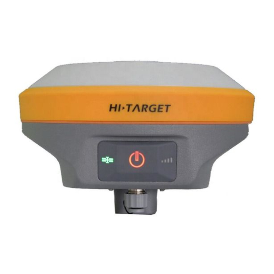
- Page 8 4. Bottom Cover 5. Upper Cover V90 Plus mainly consists of three parts, the upper cover, bottom cover and the control panel. In the middle of the mainframe is the control panel which contains a power button and three indicator lamps.
- Page 9 Products Introductions Bottom Cover Bottom Inside of the battery compartment 1. USB interface and protective plug (it is used to export data and upgrade firmware) 2. Speaker (timely operate the instrument and broadcast the status with voice) 3. Metal buckle 4.
- Page 10 V90 Plus GNSS RTK System Getting Started 8. SD card slot (it is used to place SD card, which can store massive static data) 9. SIM card slot power seat (when communicating with GSM data, it is used to place SIM card.) 10.
- Page 11 Negative pole Recharge BL-5000 lithium battery shall use Hi-Target CL-8410 lithium battery charger to charge. About 7 hours of charging time CL-8410 charger is designed with charge lamp. The lamp is red during charging process and turns green upon finishing charging. The battery is full continue charging for another 1-1.5 hours.
-
Page 12: Introductions To Ihand20 Controller
V90 Plus GNSS RTK System Getting Started 1.4 Introductions to iHand20 controller Front of handheld controller The front of iHand20 handheld controller includes touch screen, keyboard and microphone. Touch screen Keyboard Touch screen: Multipoint capacitive touch screen with touch pen, which supports Chinese and English input. - Page 13 Products Introductions Reverse side of handheld controller There are camera, battery cover, belt, trumpet, etc. on the reverse side of iHand20 handheld controller. Camera Speaker Battery cover NFC Chip Belt Buckle Camera: Used for field collection of image information. Battery cover: Internal removable lithium battery. Belt Buckle: Connect the belt to prevent sliding down.
- Page 14 V90 Plus GNSS RTK System Getting Started Side of handheld controller Waterproof & dustproof rubber cover Audio port Mini USB Fig.2- 3 Mini USB: Used for connecting USB data line and iHand20 handheld controller. Audio port: Used for connecting headphone cable and iHand20 handheld controller.
- Page 15 Products Introductions Battery Lithium battery: 3.7V /6300mAh Data line Connect to the USB port of computer, and used for download of data Connect to the USB port of charger and used for charging handheld controller Touch pen In case of using touch pen to operate the handheld controller, it is required to start the function of "handwriting pen", and open the handheld controller’s [system setting] →...
- Page 16 Operation of handheld controller Keyboard Most settings and operations of Hi-Target iHand20 handheld controller can be completed by the touch pen, and commonly used operations can be completed by keyboard. Appearance and functions of keyboard are introduced briefly as follows.
- Page 17 Products Introductions APP: Quick start of Hi-Survey software, press button APP for a long time for the Road popup, then select "Hi-Survey Road" and click [Ok]. And the software selected this time can be started quickly only by pressing key APP next time. Cautions: When installing Hi-Survey Road for the first time, it is necessary to press key APP for 3s for software quick start selection settings.
- Page 18 V90 Plus GNSS RTK System Getting Started Collect button: Collect data by manual operation. Camera button: Press it for a short time to enter into photograph interface; Press it for 3s on the non-camera interface to start up/shut down flashlight function.
- Page 19 Products Introductions Data download Connect handheld controller to computer 1. Connect handheld controller to computer by supporting USB data line, and pull down the notice column and click USB computer connection [open USB storage]. 2. If it is required to synchronously operate handheld controller or install and use third-party software to debug data on the computer, "USB debugging"...
- Page 20 V90 Plus GNSS RTK System Getting Started Click[System Settings] [Developer options]...
- Page 21 Products Introductions [USB debugging] 3. In the popup debugging window, click [OK] to complete the connection between handheld controller and computer. 4. In the computer, file operations between handheld controller and computer can be conducted by [Portable Devices].
-
Page 22: Cautions For Use
V90 Plus GNSS RTK System Getting Started 1.5 Cautions for use Environmental Requirements The receiver shall operate in dry working environment regardless of waterproof materials. In order to advance the stability and service cycle of receiver, the receiver shall be prevented from extreme environment, such as: ◆Moisture... -
Page 23: Basic Operation
Basic Operation C C C C H H H H A A A A P P P P T T T T E E E E R R R R Basic Operation ■ Button operation ■ LED indicator lamp ■ WIFI password setting ■... -
Page 24: Button Operation
V90 Plus adopts optimized and simplified design,button operation with control panel is more convenient and concise. 1. Control panel Most settings and operations of V90 Plus Receiver can be conducted by power button, below is control panel. Satellite lamp Differential... -
Page 25: Led Indicator Lamp
Basic Operation 3. Power on/off Press power button for 1s to power on. Long press power button (3s≤long press time≤6s) when voice prompts "dingdong" and release button to power off. 4. Reset main board In power on status, long press power button for more than 6s when voice prompts the second "dingdong", then release it. -
Page 26: Wifi Password Setting
Reset main board or static collecting error of 3 lamps (Insufficient storage space ) 2.3 WIFI password setting V90 Plus receiver can used as WiFi hotspot, support user-defined password (Factory default password:12345678) Cautions: 1.See WiFi factory default password in attached list1 2.If you forget your password, you can reset your password by”GNSS Receiver Manager V1.0.3”,... -
Page 27: Static Data Collecting (By Button Operation)
Basic Operation 2.4 Static data collecting V90 Plus GNSS Receiver can collect static data. relative operations are as below. 1. Set up receiver on a control point, centering and leveling strictly. 2. Measure the height of receiver for three times, on condition that the difference of each measuring is less than 3mm and the final height of the receiver should be the average height. - Page 28 Don’t move the tri-brach or change the collecting set while the receiver is collecting data. V90 Plus default settings will not record Rinex format data .Users can change relative settings by GNSS Receiver Manager software. Below is the GNSS Receiver Manager software interface.
-
Page 29: Hi-Survey
Hi-Survey C C C C H H H H A A A A P P P P T T T T E E E E R R R R Hi-Survey ■ Project settings ■ Data collecting ■ Staking out ■ Data exporting ■... - Page 30 V90 Plus GNSS RTK System Getting Started 3. Hi-Survey 3.1 Project settings ■ New project ■ Project settings ■ Device connecting ■ Base setting ■ Rove setting 1. New project After new project is built before the measurement, the collected data will be saved in the project.
- Page 31 Hi-Survey 2. "Project Info": New project can be built and the existing project can be opened or deleted. 3.Input project name in "Name" box->click "OK"; (Note: The name of new project shall not be the same as the name of old projects) 2.
- Page 32 V90 Plus GNSS RTK System Getting Started For measurement, coordinate system must be configured, because it is related to the accuracy of coordinate. There are two methods to set the coordinate system. A. build a new coordinate system, including ellipsoid projection and ellipsoid transformation parameters, etc.
- Page 33 Hi-Survey A. Build a coordinate system (1) Click "Projection"-> ->User Defined 1.Click " " to enter into the setting interface. 2. User Defined: User can conduct settings according to local parameter. Notice:Any question about “Users Defined” pleases contact technical support...
- Page 34 V90 Plus GNSS RTK System Getting Started B. Add existing coordinate system files 1) Click " " ->Select .dam File; Click " " to return the parent directory. Path: SD Card ->ZHD->Geo Path ->select .dam file (take the addition of DD. dam for example) ->click "OK".
- Page 35 Hi-Survey 3. Click" " to return to the parent directory. 4. Select coordinate system files, with the suffix of .dam. And click "OK" to complete the selection. C.Add coordinate system files (Hi-Survey software BYO) The software adds many coordinate systems all over the world intelligently for reference and selection.
- Page 36 3.select the file and Click "Apply" to apply it current project. 3. Device connecting V90 Plus as a new generation of intelligent GNSS receiver, its connection ways with iHand20 become various .receiver can connect iHand20 by Bluetooth or WiFi. Notice:NFC used to quickly establish Bluetooth connection.
- Page 37 Hi-Survey Bluetooth connection Receiver is connected with handheld controller by Bluetooth, therefore, it is necessary to do this step before the operation. If conducting RTK under the mode of UHF , two sets of receiver Bluetooth shall be configured at least(one for Base and one for Rover). 1.
- Page 38 V90 Plus GNSS RTK System Getting Started 3. Select S/N code of the device to be connected->input Bluetooth PIN"1234"; 4. After connection, the interface will display current work mode, firmware version, firmware version of GPS main -board and log-on message,...
- Page 39 Hi-Survey WiFi connection V90 Plus can be connected with iHand20 by WiFi. Connection steps are as below. 1. Power on iHand20 and run Hi-Survey software. 2. Run V90 Plus WiFi function, and click "others". 3. Choose "Receiver Settings" 4. Launch Wifi;...
- Page 40 V90 Plus GNSS RTK System Getting Started Detail operations as below show 1. Long press "APP" button. 2. Choose "Hi-Survey Road"->Click "NFC"->Click "OK".
- Page 41 Hi-Survey 3. Take iHand20 NFC response area close to receiver's NFC response area. NFC response area 4. Base setting Base operation guidelines Base parameters settings in Hi-Survey Base operation guidelines For good performance, read the following guidelines, Below will describes best practices for setting up the base, and outlines the precautions that users need to take to protect the GNSS receiver.
- Page 42 V90 Plus GNSS RTK System Getting Started Including: coordinate of Base, communication mode, difference scheme, etc.. Base is responsible for transmitting difference to the Rover so as to conduct real-time kinematic. The Base can be set by iHand20 after receiver Bluetooth has been connected.
- Page 43 Hi-Survey 3. For example: Set 11600002 as Base; 4. Select "type of antenna" ->input "target height"(Target H) Notes: Select type of antenna according to the type of receiver Notice: Pole height ---Reading from scale of centering rod . Slant height---Measuring from control point to Measurement bench marker.
- Page 44 V90 Plus GNSS RTK System Getting Started Slant height is normally used for the Base and pole height is commonly used for the Rover. (2)There are three methods to set "coordinate of Base": A. Input with known point. B. Get by average.
- Page 45 Hi-Survey B. Get by average 1) Click" "->Click "OK" to obtain position of Base. 1. Click" " 2. Click "OK" to obtain position of Base.
- Page 46 V90 Plus GNSS RTK System Getting Started C. Obtain from point library 1. Click" " 2. In the point library, there are "original data" and "control point" data, etc. for optional.
- Page 47 Hi-Survey (3) Set data chain, including A. "Internal UHF", B."Internal GSM" (Omitted), C."External Device" 1. Click "Datalink" 2. There are 4 kinds of data chain, which are Internal UHF, Internal GSM, External Device and External Network(3G). A. "Internal UHF" 1) Data link->select "Internal UHF"...
- Page 48 V90 Plus GNSS RTK System Getting Started 2) Set "Chanel", "Sky Baud rate", "Power", etc. Data-link : Internal UHF(for example) Channel: 0-116 channels (DDTR-type instrument transceiver) for optional, 0-32 channels (PCC transceiver) Sky Baud rate: Choosing transmit rate at 19200 or 9600 Power: low, medium and high power.
- Page 49 Hi-Survey 4) Click "Set" to complete the setting of Base Click "Set" to complete the setting of Base If the setting of Base is completed, the software prompts "setting of Rover". C. "External Device" 1) Datalink-> select "External Device";...
- Page 50 V90 Plus GNSS RTK System Getting Started 1. When Base data chain selects "External Device", channel of transceiver will be determined by the external device. 2. Other settings Same as UHF setting method. 3. Click "Set" to complete the setting...
- Page 51 Hi-Survey 5. Rover setting (1) After completing setting of Base, enter into "setting of Rover" ->select "Yes"->click "Connect" to set the Rover. 1.Click "Yes" to jump to setting of Rover 2.Click "Connect"...
- Page 52 V90 Plus GNSS RTK System Getting Started (2) Click "Connect" and select receiver equipped with Bluetooth If the device has not been equipped with the Bluetooth, please refer to above "Bluetooth connection" method for configuration. The connected instrument can display fuselage number (Such as: 10211158) (3) Set Rover "Data-link", including "Channel"...
- Page 53 Hi-Survey Data-link: Internal UHF Conformity with Base(take 6 for example) Conformity with Base(take 19200 for example) (4) When Base communicates with the Rover successfully and differential lamp (middle lamp) in both Base and Rover flash red. 6. Floating box Common Satellites-Satellites Solution Receiver power Correction...
- Page 54 V90 Plus GNSS RTK System Getting Started "Correction latency": Refers to calculating time after Rover receives the signal from Base. "PDOP value": Intensity factor of space geometry where the satellite is distributed. Generally, the better the satellite distribution is, the smaller the PDOP value is. Generally, the value is less than 3 as the more ideal state.
- Page 55 Hi-Survey (2) Stellar map ◇ Distribution situation of projection position of satellite can be viewed. Roundness refers to GPS satellite and SBAS satellite, square refers to GLONASS and BDS satellite. GPS: Prn value is 1-32; GLONASS: Prn value is 65-96; BDS: Prn value is 161-197. ◇...
- Page 56 V90 Plus GNSS RTK System Getting Started Click "Status" (3) Signal-to-noise ratio figure of satellite: Prn refers to number of satellite; Azi refers to azimuth angle of satellite; Ele refers to satellite elevation, L1 refers to signal to noise ratio of L1, and L2 refers to signal to noise ratio of L2.
- Page 57 Hi-Survey 3.2 Data collecting ■ Single-point collection ■ Average collection ■ Automatic collection ■ E-bubble(electronic bubble) centered Auto-collection ■ Tilt survey After the settings for the above project and Base as well as Rover are completed successfully, enter into data collection interface for collection. Corresponding collection methods can be selected according to different demands.
- Page 58 V90 Plus GNSS RTK System Getting Started Detail Survey 1. Single-point collection Single-point collection means collecting the data of each point by manual operation. (1) Click " "->" " Click " "...
- Page 59 Hi-Survey Click " " ( Single Press " " on the keyboard can also collect point ) (2) Input information of collection point, including point name, target height (the first point needs to be measured and the next points can be defaulted) and point position description (non-input optional).Click "OK"...
- Page 60 V90 Plus GNSS RTK System Getting Started Target H: Target height (determined according to actual height), including three kinds: Pole, Vertical and Slant. 2. Average collection That is averaging for the multi-measurement value of coordinate for each point. 1. Click "...
- Page 61 Hi-Survey 2.After the average collection, click "OK" 3.Input information of point name (Name), Target Height (Target H), Description (Desc) and Station After inputting, click "OK"...
- Page 62 V90 Plus GNSS RTK System Getting Started 4.At the moment, the point will be saved Setting method of average collection: 1.Click "Config" to enter into average collection setting interface.
- Page 63 Hi-Survey 2. Available to set the average times. 3. Automatic collection Point measurement will be recorded automatically according to the configured record condition. 1.Click " "to start automatic collection.
- Page 64 V90 Plus GNSS RTK System Getting Started 2. Collection setting, including sampling interval (time or distance), point name and number, etc.(user-defined available) 3. Click "OK" to start collection.
- Page 65 Hi-Survey The collected point can be stored automatically. 4. Click " " to stop automatic collection; 4. E-bubble centered Auto-collection When users open the electronic bubble calibration function, users can choose e-bubble(electronic...
- Page 66 V90 Plus GNSS RTK System Getting Started bubble)auto-survey mode and collect data automatically when e-bubble is centering. That innovative function makes surveying work more efficient and greatly convenient for surveyor's operation. 1.Go to survey interface and choose "Auto collect "...
- Page 67 Hi-Survey 3. When the electronic bubble is center it will auto collected ( It is very convenient). 5.Tilt survey After Electronic bubble calibration, direction sensor calibration and attitude deviation calibration are successful, then begin to do Tilt survey. Tilt survey condition: Tilt within 20 degrees under motionless state. (1) Open "Slope correction"...
- Page 68 V90 Plus GNSS RTK System Getting Started Detail Survey-> Config Data -> open "Slope Correction" (If "off" the "Slope Correction", software will not make slope correction.)...
- Page 69 Hi-Survey (2) Start to record point (3) Add slope correction process. a. Click "Raw Data"-> Choose "Proce (Process)" 1.Click "Raw Data"...
- Page 70 V90 Plus GNSS RTK System Getting Started 2.Choose "Proce" b. Choose "Slope Correction"-> Process, then make a correction and upgrade the coordinate points. 1.Choose "Slope Correction"-> Process...
- Page 71 Hi-Survey 2. Process data success. Notice: 1. Tilt survey angle must less than 30°,otherwise the inclination correction will not satisfy users 2. Before ending tilt survey, please conduct "Process" and software will make a correction and upgrade the coordinate points. 3.
- Page 72 V90 Plus GNSS RTK System Getting Started 6. View all collected points 1.Click "Project"->Points in the software main interface 2.Inquire the point library...
- Page 73 Hi-Survey 3.3 Stake out ■ Point Staking ■ Line Staking ■ Dxf Staking Staking, refers to mark the plane position and elevation of buildings and structures planned and designed on the design drawing on the ground with certain measuring method according to required precision as the basis of construction.
- Page 74 V90 Plus GNSS RTK System Getting Started 2. Click" "(enter into point selection interface) Enter into "Select Stake Point" interface...
- Page 75 Hi-Survey This step has three point selection methods (Choose either), namely, A. Input coordinate; B. Select from coordinate library; C. Select from graph. A. Directly input coordinate 1) Input "Name"->Input" NEZ "coordinate->Click "OK" Input the point’s name and coordinate, tick "Save to Stake Pts Lib"...
- Page 76 V90 Plus GNSS RTK System Getting Started Stake interface Backward: Southward Towards the Right: Eastward Delta H: Altitude difference between stake coordinate and actual position Name : name of stake point σ: Relative precision HD: Horizontal Distance B. Select from coordinate library.
- Page 77 Hi-Survey select coordinate point. 2) Tick Save to stake Pts Lib->Click "ok" Tick Save to stake Pts Lib->click "OK", add the coordinate point from the "Point Library" to the "Stake Point Library".
- Page 78 V90 Plus GNSS RTK System Getting Started 3) Input keyword->Click " " of point name in "Name" Click " " of point name in "Name" Inquire result, select the required point and click "OK" to start stake.
- Page 79 Hi-Survey 4) Start staking-out Stake interface (indicate position of target point) Backward: Southward Towards the Right: Eastward Delta H: Altitude difference between stake coordinate and actual position Name : Name of stake point σ: Relative precision HD: Horizontal Distance...
- Page 80 V90 Plus GNSS RTK System Getting Started C. Select from graph. 1) Click " "Select stake point on Map. Click " ", the software can extract the coordinate of stake point library automatically in the positive sequence or negative sequence for stake.
- Page 81 Hi-Survey 2) Click "OK" to start staking-out Start staking-out Stake interface (indicate position of target point) Backward: Southward Towards the Right: Eastward Delta H: Altitude difference between stake coordinate and actual position Name: Name of stake point σ: Relative precision HD: Horizontal Distance...
- Page 82 V90 Plus GNSS RTK System Getting Started 2. Line staking 1. Stake line from line library. 1. Click "Survey"->"Stake Line"->Click" " to enter into the stake line interface; Click "Survey"->"Stake Line"...
- Page 83 Hi-Survey 2. Click " "-> Click "Add"...
- Page 84 V90 Plus GNSS RTK System Getting Started 2. Define straight line: There are 2 methods to define the straight line, See as below shows. There are 2 methods to define the straight line (select one according to situation), A. "2Points to define the line"...
- Page 85 Hi-Survey 2.Select "Start Point" and "End Point" and click "OK" 2) At the moment, the straight line is added successfully, which also can be edited and deleted, etc. 1.The added straight line can be viewed in the interface.
- Page 86 V90 Plus GNSS RTK System Getting Started 2. Selected line can be edited and deleted B. "One point + Azimuth angle" 1) Click "Add"->line->"Point + Azi" 1.Click "Add"->line...
- Page 87 Hi-Survey 2. Tick "Point + Azi" 2) Select "Start point"->Input "Azi"->Click "Length" to input length of stake line->Click "OK" to complete the addition of straight line; 1.Input the name of straight line and add coordinate and azimuth angle of "Start Point".
- Page 88 V90 Plus GNSS RTK System Getting Started 2. When extract the coordinate of one point from the point library, input azimuth angle (Azi) of straight line and start station. Length refers to length of stake straight line. 3. If added successfully, the added...
- Page 89 Hi-Survey 3. Start to stake after adding the stake straight line successfully. (1) Click " "->click "Milestone" to input milestone of point to be staked->click "OK" to enter into the stake interface. Cautions: Where the milestone and offset can be accumulated automatically according to the increment.
- Page 90 V90 Plus GNSS RTK System Getting Started (2) Click " " again to enter into next point station in which station and offset can be accumulated automatically based on increment. 3. Dxf file staking 1. Importing Dxf file as below shows.
- Page 91 Hi-Survey 3.Select "Dxf" file to be imported -> click "OK" 4. Click "Blank" part->select import format, such as (Name,N,E,Z, etc.), and click "OK" to complete the import.
- Page 92 V90 Plus GNSS RTK System Getting Started 3.4 Data Export Data achievement export supports the following format: *.txt, *.CSV, *.dxf, (shp File)*.shp and (Excel File)*.csv. The export procedures are as follows. 1.Click" Data Transfer" 2.Select "Export" and Input name of File->Select Export Format->Select...
- Page 93 Hi-Survey 4. Select file format (take *.dxf for example) ->click "OK" to complete data export. Export format of file includes(8kinds): User-defined(*.txt), User-defined(*.CSV), DxfFile(*.dxf), ShpFile(*.shp), Excel File(*.CSV), South cass7.0(*.dat), Scsg2000(*.dat), PREGEO(*.dat).
- Page 94 V90 Plus GNSS RTK System Getting Started 3.5 Auto-backup function in Hi-Survey Project is auto restored in Hi-Survey. External SD card is used for important data backup (Including: Raw data, project file, coordinate system or encryption QR code file). There are two kinds of backup, one is when users is setting project info he can click the auto-backup in advance;Another is when users is deleting project file and choose "Backup"...
- Page 95 Hi-Survey 2. Select "Recov" 3. Open "Auto backup" Notice:The path of backup file:external SD card /ZHD-Bak/Project/Road.
- Page 96 V90 Plus GNSS RTK System Getting Started 2. Backup before delete Backup before delete means users backup project file into external SD card before delete project file .The path of backup file:external SD card /ZHD-Bak/Project/Road. (1) Choose delete project file and long press it in "Project info"...
- Page 97 Hi-Survey 3. Data Recovery 1.Click "Recov" in "Project Info" 2.Long press to choose backup file , " " represent all selected After selected file, Click " Start Recovery "...
- Page 98 V90 Plus GNSS RTK System Getting Started 4. Backup/ Recovery path: external SD card /ZHD-Bak/Project/Road. View backup file:File Manager->SD card->ZHD-Bak->Project->Road File Manager->SD card->ZHD-Bak->Project->Road Notice: 1. External SD card is necessary before users backup project file. 2. All the backup operations are over version 1.0.2.
-
Page 99: Simplified Operation Of Survce
Simplified Operation of SurvCE C C C C H H H H A A A A P P P P T T T T E E E E R R R R Simplified Operation of SurvCE... - Page 100 V90 Plus GNSS RTK System Getting Started 4.Simplified Operation of SurvCE 1. Open "SurvCE" software Select "Select New/Existing Job" to jump for selecting to open existing project or newly established project. Input Project Name Then Click " ". 2. After project establishment, enter into "Setting" in the coordinate system. There are two ways: A.
- Page 101 Simplified Operation of SurvCE A. Import existing coordinate system. Click "Add Predefined"->Select coordinate system->Click" " to complete the addition of coordinate system. Click "Add Predefined" Click " " to complete the addition of coordinate system B. User-defined coordinate system Coordinate system can also be manually modified.
- Page 102 V90 Plus GNSS RTK System Getting Started 3. Connect instrument and set Base The connection between controller and receiver is established by Bluetooth. 1) Click "Equip"->GPS Base Interface of GPS Base setting: Manufacturer: Select "Hi-Target" Model (optional): Select corresponding model...
- Page 103 Simplified Operation of SurvCE 2) Click "Comms"->Type: Bluetooth->click ->Find Device-(Search for Bluetooth device) Click "Comms" -> Type: Bluetooth Click" "->Find Device (Search for bluetooth device)
- Page 104 V90 Plus GNSS RTK System Getting Started 3) Select instrument as "Base">Set Device PIN>click " ", at the moment, the Bluetooth connection is successful. Select S/N of instrument as "Base", click" " Set Device PIN,Input "1234" Click " " to complete the connection 4) Click "RTK"...
- Page 105 Simplified Operation of SurvCE Click" " enter into transceiver setting click" " to complete 5) For obtaining coordinates of Base click "Read From GPS"->smooth obtaining ->click "Yes"...
- Page 106 V90 Plus GNSS RTK System Getting Started Average setting "By Number" or "By Time in min" for optional 4. Set Rover The procedures to set rover are similar as to base. Note: 1. When receiver works in UHF mode, settings should be exactly same as the Base 2.
-
Page 107: Trouble Shooting
Trouble Shooting C C C C H H H H A A A A P P P P T T T T E E E E R R R R Trouble Shooting ■ Reset operation ■ Restore the iHand20 to factory settings ■... -
Page 108: Reset Operation
V90 Plus GNSS RTK System Getting Started 5.Trouble Shooting 5.1 Reset operation When the Bluetooth is not connected, satellite searching fails and network connection fails, the operation can be conducted in case that instrument restarting does not work. Reset receiver : In power on status ,long press power button(3s≤long press time≤6s) when voice prompts first "dingdong"... - Page 109 Trouble Shooting (2) Press to enter the following interface. 2. Wipe user data: Press “ & ”keys to move the cursor and highlight “wipe data/factory reset”, and then press to enter the following interface. 3. Move the cursor and highlight” yes—delete all user data” ,than press to confirm and delete the user data.
-
Page 110: Usb Virtual Serial Port Driver Installation
V90 Plus GNSS RTK System Getting Started 5. Highlight “reboot system now”, press to confirm and restart the phone. 5.3 USB virtual serial port driver installation Installation steps are as follows. 1. Confirm to open the virtual serial port driver function, users can view and check these settings by iHand20. - Page 111 Trouble Shooting 4. Choose "Skip obtaining driver software from Windows update" and open "Computer management"; In "Other devices" choose the "CDC Serial" 5. Right click "CDC Serial" and choose "Upgrade Driver Software" and select"linux_cdc_seial.inf " then click next.
- Page 112 V90 Plus GNSS RTK System Getting Started 6. If searched the effective software, the pop-up window will appear, and choose "Install this driver software anyway". 7. Successfully updated information will show as below.
-
Page 113: Firmware Update
5.4 Firmware update Receiver’s firmware updating steps are showed as below. 1. Power on V90 Plus GNSS receiver, connect receiver with PC by manufacture equipped USB cable. Then open "My Computer" ," update "disk will display. 2. Copy the firmware to "update" disk, remove it and disconnect USB cable, restart GNSS receiver. - Page 114 V90 Plus GNSS RTK System Getting Started 2. Modify radio parameters There are two ways to modify the radio parameters which including Bandwidth,Channels,Radio Link and Protocol. 1) Manually modify Choose radio->input "RX" and "RY"-> Apply->Program; The other parameters can be modified in the corresponding selection box.
- Page 115 Trouble Shooting (1) Click "Import" (2) Choose file->Open (File format:*.ini)
- Page 116 V90 Plus GNSS RTK System Getting Started (3) Click" Program" (4)Set parameters Ok! Note: 1. When the parameters modification is OK, you can export it into parameter sheet (*.ini ) file then import and apply it to other receivers. 2. Please restart the GNSS receiver after conducted.
-
Page 117: Technical Parameters
Technical Parameters C C C C H H H H A A A A P P P P T T T T E E E E R R R R Technical Parameters ■ GNSS receiver ■ Communication ■ Controller... -
Page 118: Gnss Receiver
V90 Plus GNSS RTK System Getting Started 6.Technical Parameters 6.1 GNSS receiver Satellite Signals Tracked Simultaneously 220 Channels Simultaneous L1C/A, L2C, L2E, L5 GLONASS Simultaneous L1C/A, L1P, L2C/A (GLONASS M only), L2P SBAS Simultaneous L1 C/A, L5 Galileo Simultaneous L1 BOC, E5A, E5B, E5AltBOC(optional) - Page 119 Technical Parameters Initialization reliability Typically > 99.9% Code Differential GNSS Positioning Horizontal 25cm+1ppm RMS Vertical 50cm+1ppm RMS SBAS 0.50m Horizontal, 0.85m Vertical Hardware Physical Dimensions (W x H) 153mm x 83mm (6.02inch x 3.27inch) Weight ≤1.0kg without internal battery Operating temperature -40℃to +65℃...
-
Page 120: Communication
V90 Plus GNSS RTK System Getting Started 1 x TNC antenna connector 1x built-in lithium battery interface Tilt Survey System Electronic Bubble System Configuration AM3352CotexA8 Platform Storage 16GB Internal storage (Support up to 32GB external SD card) Record GNS and RINEX format simultaneously... -
Page 121: Controller
0.5W, 2W adjustable Transmitting speed Up to 19.2Kbps Support most of radio communication protocol Working range 3~5km typical, 8~10km optimal HI-TARGET External UHF Radio (Standard) Frequency 460MHz with 116 channels Transmitting power 5W, 10W, 20W, 30W adjustable Transmitting speed Up to 19.2Kbps... - Page 122 V90 Plus GNSS RTK System Getting Started...
- Page 123 Technical Parameters...
-
Page 124: Socket And Main Accessories
V90 Plus GNSS RTK System Getting Started C C C C H H H H A A A A P P P P T T T T E E E E R R R R Socket and Main Accessories ■ Preface ■... - Page 125 The chapter will introduce the appearance and application of main interface of receiver and accessories. The following equipment does not represent all users purchased V90 Plus. According to different configurations, the specific configuration shall be subject to the delivery order upon purchasing.
- Page 126 V90 Plus GNSS RTK System Getting Started Data Cable Five-pin plug Series interface Five-pin plug: connect Five-pin socket of receiver Serial interface: it is used to connect with computer serial port, update receiver firmware, set the receiver, manage static data and set the radio.
- Page 127 Socket and Main Accessories 1. Field intensity/power voltage indicator D1 2. Dibit nixie tube indicator D2 3. Send-receive indicator light D3 4. Power/warning indicator D4 5. Key K4 (power on-off key) 6. Key K4 (channel increasing key) 7. Key K3 (channel decreasing key) 8.
- Page 128 V90 Plus GNSS RTK System Getting Started Annexed Table 1 Defaulted Frequency Table upon Delivery The user may change defaulted frequency of 16 channels of the radio. Table 1 Defaulted frequency table of 16 channels in radio Frequency(MHZ) Frequency(MHZ) Channel Channel 466.825...
Need help?
Do you have a question about the V90 Plus and is the answer not in the manual?
Questions and answers