Table of Contents
Advertisement
Advertisement
Table of Contents

Related Manuals for Hi-Target vRTK


Summary of Contents for Hi-Target vRTK
- Page 1 GNSS RTK System User Manual...
- Page 2 User Manual Manual Revision Revision Date Revision Level Description vRTK GNSS RTK System April. 2022 User Manual...
- Page 3 User Manual vRTK GNSS RTK System User Manual...
-
Page 4: Tips For Safe Use
Before using the product, please read these operating instructions carefully, as they will help you to get the most from it. Hi-Target Surveying Instrument Co. Ltd assumes no responsibility if you fail to operate the product according to the instructions or operate it wrongly because you have misunderstood them. -
Page 5: Technology And Service
User Manual Technology and service If you have any technical issues, please call the Hi-Target technology department for help, and we will answer any questions you have. Relevant information You can obtain this introduction by: Purchasing Hi-Target products: this manual is found in the instrument container and will help you to operate the instrument. -
Page 6: Table Of Contents
User Manual Contents Preface ..................................I Introduction ................................I Tips for safe use ..............................I Exclusions ................................I Technology and service ............................ II Relevant information ............................II Advice .................................. II Contents ...................................III Chapter 1 .................................1 Overview ................................1 1.1 Foreword ...............................2 1.2 Features ................................2 1.3 Use and precautions ........................... - Page 7 User Manual 2.4.1 Static settings ............................21 2.4.2 Static data collection steps ........................22 2.4.3 Static Data Download ..........................22 2.5 Tilt Survey ..............................24 2.5.1 Calibration-free Tilt Survey ........................24 2.6 Firmware Upgrade ............................25 2.6.1 Upgrade by USB Cable ........................... 25 2.6.2 Upgrade by Using the Web Management System ................
-
Page 8: Chapter 1
User Manual Chapter 1 Overview This chapter contains: - Foreword - Features - Use and precautions... -
Page 9: Foreword
AR release. It deploys an advanced RTK engine and a new generation of sensorless IMU, making tilt measurement much easier, while the new generation GNSS chip guarantees speed and accuracy. This means that you can count on vRTK to provide you with improved productivity. - Page 10 User Manual Notice: This equipment complies with radiation exposure limits set forth for a controlled environment. This equipment should be installed and operated with a minimum distance of 1m between the radiator and your body. This transmitter must not be co-located or operated in conjunction with any other antenna or transmitter.
-
Page 11: Chapter 2
GNSS System User Manual Chapter 2 Product introduction This chapter contains: - Overall appearance - Button & LED - WEB management system - Static survey - Tilt survey - Firmware upgrade - Image measurement - AR Stake... -
Page 12: Overall Appearance
GNSS System User Manual 2.1 Overall appearance The product’s appearance is divided into three parts, the upper cover, bottom cover and control panel. Figure 2-1-1 2.1.1 Upper cover Figure 2-1-2 2.1.2 Bottom cover The bottom cover includes the SMA antenna interface and Type-C USB interface. -
Page 13: Control Cover
GNSS System User Manual Figure 2-1-3 1. Type-C USB interface 2. Connection screw 3. Speaker 4. SMA antenna interface ◇ SMA antenna interface: Connect the radio antenna while using the Internal UHF mode. ◇ Type-C USB interface: To upgrade firmware and download static data. - Page 14 GNSS System User Manual Figure 2-1-4 1. Satellite LED 2. Data LED 3. Power button...
-
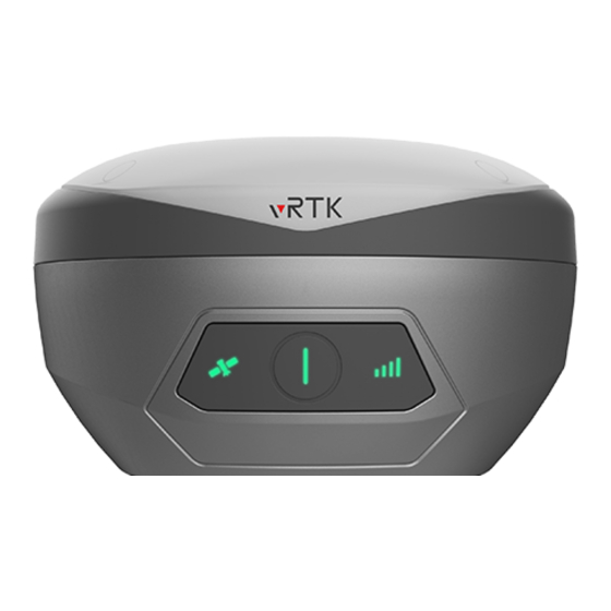
Page 15: Button & Led
GNSS System User Manual 2.2 Button & LED 2.2.1 Button function Table 2-2-1 Button function description Function Description Power-on Press and hold the power button for 1 second. Power-off Press and hold the power button for more than 3 seconds but less than 6 seconds. -
Page 16: Web Management System
The satellite is not tracked. 2.3 WEB management system The vRTK unit has a built-in web management system that can be used to set the receiver's working mode and data output, as well as viewing receiver and satellite information. The receiver’s Wi-Fi name is its S/N. - Page 17 GNSS System User Manual Figure 2-3-3 Information Figure 2-3-4 Work mode Figure 2-3-5 File manager Figure 2-3-6 Firmware...
- Page 18 GNSS System User Manual Figure 2-3-7 System Figure 2-3-8 Coordinate System Main menu Sub-menu Description Device info Device model, version, registration info, etc. Position info Coordinates, satellite tracking, solution state, etc. Information Base info Coordinates and distance to the base...
-
Page 19: Information
GNSS System User Manual 2.3.2 Information 1. Device information This includes the main information about the device: device model, S/N, firmware version, OEM info, battery power, work mode, configuration parameters and others. Figure 2-3-9 Device information 2. Position information This shows the device’s position, satellites, the solution state, latency, PDOP and time. - Page 20 GNSS System User Manual Figure 2-3-11 Base information 4. Sky plot This displays satellites which are visible from the device and switches for each constellation. Figure 2-3-12 Sky plot 5. Satellites list This shows satellite tracking information.
-
Page 21: Work Mode
GNSS System User Manual Figure 2-3-13 Satellites list 2.3.3 Work Mode 1. Rover Set up the rover’s data link and its parameters. The rover station data link includes internal UHF. Figure 2-3-14 Rover 2. Base Set up the data link and parameters of the base and get point coordinates by averaging. The base... -
Page 22: File Manager
GNSS System User Manual Figure 2-3-15 Base 3. Static Set up the file name and parameters for the static collection. Note: After ticking Static Mode, you can only cancel it in the base rover setting interface. Figure 2-3-16 Static 2.3.4 File manager... -
Page 23: Firmware
GNSS System User Manual Figure 2-3-17 Static data 2.3.5 Firmware 1. Upgrade Display specific device version information. Click ‘Select’, choose the upgrade package required and then click ‘Start’. The receiver will automatically detect and upgrade the firmware. Figure 2-3-18 Upgrade 2. -
Page 24: System
GNSS System User Manual Figure 2-3-19 Restore 2.3.6 System 1. Constellation Switch off and on satellite tracking. Figure 2-3-20 Constellation 2.5 pin port Manage the output settings of the 5-pin port. - Page 25 GNSS System User Manual Figure 2-3-21 5-pin Port 3. Radio You can select the radio modulation protocol from HI-TARGET19200, HI-TARGET9600, TRIMTALK450S, TRIMTALK III, SATEL-3AS, SOUTH19200, SOUTH9600, CHC19200 and CHC9600, TRANSEOT. Figure 2-3-22 Radio 4. Registration Display the registration information of the receiver. You can select the registration type, and then enter...
- Page 26 GNSS System User Manual Figure 2-3-23 Registration 5. Reset Reset the motherboard. Figure 2-3-24 Reset 6. Others You can set the switches of the Store RINEX Data and Check Base Position, select the RINEX version, select the time zone and adjust the voice and volume of the receiver.
-
Page 27: Coordinate System
GNSS System User Manual Figure 2-3-25 Others 2.3.7 Coordinate System 1. Projection Frequently-used projections are built-in such as Gauss, Mercator and Lambert. Figure 2-3-26 Projection 2. Datum Users can define source ellipsoid, local ellipsoid and datum transfer model settings. -
Page 28: Static Survey
GNSS System User Manual Figure 2-3-27 Datum 3. DAM File Each software project corresponds to a separate ‘.dam’ file and a new file will be created when a new project is created. This will have the same name as the project. -
Page 29: Static Data Collection Steps
GNSS System User Manual 1. Hi-Survey Road software – static interface – to set up the static or temporary static mode. 2. Web interface – work mode – to set up the static or temporary static mode. Users can download the static data file to a computer, if necessary, and then use the static post- processing software (HBC data processing software package) to process the data. - Page 30 GNSS System User Manual Figure 2-4-2 Static Drive Figure 2-4-3 Static Drive 2. Download using the web management system The Wi-Fi name of the receiver is its S/N. You can connect it to a controller or phone (the default password is: 12345678) and then input the IP address 192.168.20.1 into the browser to log into the...
-
Page 31: Tilt Survey
GNSS System User Manual 2.5 Tilt Survey 2.5.1 Calibration-free Tilt Survey Connect to the receiver via the Hi-Survey Road software and open the Tilt Survey by using the option found at Survey → Surveying Configure → Data interface. Click the Tilt Survey icon and follow the prompt from the Hi-Survey Road interface to finish the initialization. -
Page 32: Firmware Upgrade
GNSS System User Manual 2.6 Firmware Upgrade You can upgrade the firmware of the receiver, motherboard and module by using a USB cable, the web management system or online remotely. 2.6.1 Upgrade by USB Cable Steps to using a USB cable to upgrade the firmware: 1. -
Page 33: Image Measurement
GNSS System User Manual 2.7 Image measurement The vRTK receivers now have new dual cameras, which support the image measurement function. The iHand55 and the Hi-Survey software are required; V2.3.0 and later versions must be used. The image measurement scene is defined as shooting the unreachable position. After the solution is successfully solved by the controller’s software, the points can be marked on the photo and their... -
Page 34: Schematic Diagram Of Video Rtk Shooting
GNSS System User Manual 2.7.2 Schematic Diagram Of Video RTK Shooting 1. Error Demonstration Figure 2-7-3 Error Demonstration 2. Correct Demonstration... -
Page 35: Ar Stake
2.8 AR Stake 2.8.1 AR Stake Instructions The vRTK receivers have newly added dual cameras, which can support the AR stakeout function. The iHand55 controller and the software Hi-Survey V2.3.0 or later versions are required. The AR stakeout scene is defined as when the stakeout point is approximately 3m from the receiver, the camera of the receiver is called, and the precise position of the stakeout point is displayed in real time through the controller. - Page 36 GNSS System User Manual Figure 2-8-1 Control Navigation Figure 2-8-2 Receiver Navigation For detailed steps, please refer to ‘Hi-Survey Software User Manual’ - Point Stakeout (AR Stakeout).
-
Page 37: Chapter 3
GNSS System User Manual Chapter 3 Technical Specification This chapter contains: - Technical Specification... -
Page 38: Technical Parameters
GNSS System User Manual 3.1 Technical Parameters Table 3-1-1 Technical Parameters Configuration Detailed Indicators Channels 1408 BDS: B1I,B2I,B3I,B1C,B2a,B2b* GPS: L1C/A,L1C,L2P(Y),L2C,L5 GLONASS: L1, L2 Satellite signals GALILEO: E1,E5a,E5b,E6* tracked simultaneously QZSS: L1,L2,L5,L6* GNSS IRNSS:L5* configuration SBAS:L1 C/A,L5 Output format ASCII: NMEA-0183, Binary data... - Page 39 GNSS System User Manual AR measure 2cm ~ 4cm precision Initialization time 2-10s Initialization >99.99% reliability Breakpoint Provides RTK measurements even during differential signal continuity test interruptions Pixel Professional Dual HD Camera, 2MP & 5MP Camera Support live view stakeout, image measurement, working distance...
- Page 40 GNSS System User Manual Water/dustproof IP68 Drop test Resist natural fall of 2m high measuring rod Relative humidity 100% non-condensing Environment Operation -40°C ~ +75°C temperature Storage -55°C ~ +85°C temperature Notice: 1. BDS B2b, GALILEO E6, QZSS L6, and IRNSS L5 are available through firmware upgrades.
-
Page 41: Chapter 4
GNSS System User Manual Chapter 4 Accessories and Interface This chapter contains: - Data cable - Antenna - Battery & charger... -
Page 42: Data Cable
GNSS System User Manual Data cable Type-C cable: Used to connect the receiver to a PC for upgrading firmware and downloading static data. Figure 4-1-1 Type-C cable 4.2 Antenna The UHF radio antenna is used in the Internal UHF mode. - Page 43 GNSS System User Manual Figure 4-3-1 Cable Figure 4-3-2 Charger Notice: Please use this product’s standard charger to charge the receiver. We will not be responsible for any accidents that occur during the charging process or any damage to the instrument if you use other chargers instead.
Need help?
Do you have a question about the vRTK and is the answer not in the manual?
Questions and answers