Raven Sidekick Pro Quick Installation Reference
Hide thumbs
Also See for Sidekick Pro:
- Installation and operation manual (98 pages) ,
- Installation & operation manual (86 pages) ,
- Installation & operation manual (64 pages)

Related Manuals for Raven Sidekick Pro


Summary of Contents for Raven Sidekick Pro
- Page 1 RCM - Sprayer with Sidekick Pro™ ICD Ratio Rate Quick Installation Reference 016-7100-049 Rev. A 10/21 E37179 Copyright 2021...
- Page 2 Raven systems, or products used as components of systems, which rely upon the reception of these signals or availability of these services. Raven Industries accepts no responsibility for the use of any of these signals or services for other than the stated purpose.
-
Page 3: Table Of Contents
Machines with Recirculation Systems ...........................12 Electrical Components and Cabling ........................16 Mount and Connect the Rate Control Module - Sprayer (RCM - Sprayer) ECU ..........16 Connect the Sidekick Pro™ ICD Pump and Cables ....................17 Extension Cables ...................................18 Master Input Signal ................................19... - Page 4 Table of Contents RCM - Sprayer with Sidekick Pro™ ICD Ratio Rate Quick Installation Reference...
-
Page 5: Chapter 2 Introduction
COMPATIBLE KITS This section contains a list of the components included in the RCM - Sprayer kit. One of the Sidekick Pro ICD kits is also required to complete the installation. -
Page 6: Rcm - Sprayer Kits
BOLT, MACHINE, HEX HEAD, 1/4-20 UNC-2 X 3, SS 311-0054-081 BOLT, HEX HEAD, 3/8-16 UNC X 1-1/4 312-1001-164 NUT, FLANGE LOCK, 3/8-16 UNC 312-4000-164 NUT, LOCK, NYLON INSERT, 1/4-20 RCM - Sprayer with Sidekick Pro™ ICD Ratio Rate Quick Installation Reference... -
Page 7: Sidekick Pro™ Icd Kits
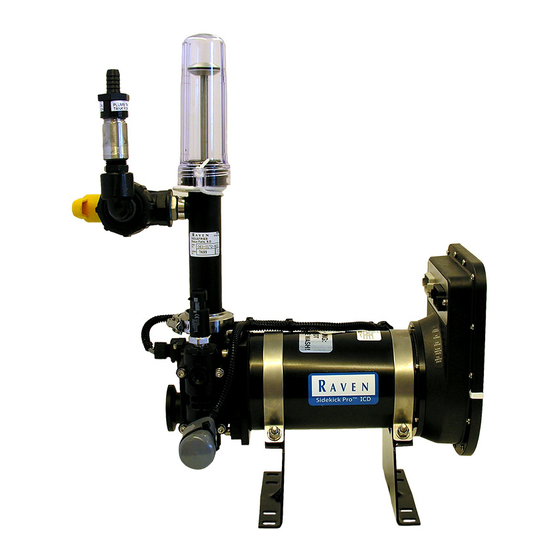
Select one of the following kits: NOTE: Refer to the Sidekick Pro™ ICD Installation and Operation Manual (P/N 016-0171-605) for additional details on rinse assist and injection module components. • 117-0175-071 KIT, SIDEKICK PRO ICD, LV W/ TANK, W/ RINSE •... - Page 8 CHAPTER 2 RCM - Sprayer with Sidekick Pro™ ICD Ratio Rate Quick Installation Reference...
-
Page 9: Chapter 3 Installation
FIGURE 2. Conventional Spray Boom Configuration with Injection MOUNT THE SIDEKICK PRO™ ICD INJECTION SYSTEM Refer to the “Mount the Sidekick Pro ICD Pump and Chemical Tank” section in the Sidekick Pro™ ICD Installation & Operation Manual (P/N 016-0171-605). • Make sure that there are no moving parts near the injection pump. This can cause damage. - Page 10 CHAPTER 3 • Mount the Sidekick Pro™ ICD in a location which provides access to the pump and ECU to simplify calibration and troubleshooting. NOTE: Length of cabling may dictate available mounting locations. The following figures offer some examples of how to mount the Sidekick Pro™ ICD injection module.
-
Page 11: Plumb The Injection System
INSTALLATION PLUMB THE INJECTION SYSTEM Refer to the Sidekick Pro™ ICD Installation & Operation Manual (P/N 016-0171-605) for details on plumbing the injection system including closed calibration. Optionally, the pump may be plumbed as shown in the figure below. FIGURE 5. Sidekick Pro™ ICD without Closed Calibration System MOUNT RINSE VALVE Refer to the Sidekick Pro™... -
Page 12: Assemble And Mount The Mixer
3. Place a 3-way hand valve up-stream from the check valve if possible. This valve may be used to drain the system or for a manual catch test. RCM - Sprayer with Sidekick Pro™ ICD Ratio Rate Quick Installation Reference... - Page 13 Raven Mixer Raven Control (P/N 063-0173-737) Module - Sprayer (RCM - Sprayer) (P/N 063-0173-951) RCM - Sprayer Product Control Injection Point Cable (P/N 333-0014-002) (P/N 115-7301-032) Pressure Sensor Check Valve (P/N 422-0000-119) (P/N 333-0014-004) Raven Flow Meter (P/N 063-0173-291) Installation:...
-
Page 14: Machines With Recirculation Systems
MACHINES WITH RECIRCULATION SYSTEMS NOTE: The Sidekick Pro™ ICD injection pump should not be used with boom recirculation systems. Boom recirculation returns injected and mixed chemicals back to the main tank, which can cause clumping and other issues with the sprayer system. - Page 15 INSTALLATION FIGURE 10. Recirculation with 3-Way Valve on Sprayer 3-Way 3-Way Outlet Inlet Valve Valve Flow Meter Recirculation Pump Point of Injection Mixer Sprayer 3-Way Valve Spray Boom FIGURE 11. 2-Way Valve on Sprayer (Before Recirculation) Installation:...
- Page 16 FIGURE 13. Mixer and Valves Mounted Near Sprayer Boom 3-Way Outlet Valve 3-Way Inlet Valve Check Valve Raven Mixer Flow Meter (P/N 063-0173-737) Raven Check Valve Recirculation Pump Pressure Sensor RCM - Sprayer with Sidekick Pro™ ICD Ratio Rate Quick Installation Reference...
- Page 17 INSTALLATION FIGURE 14. Alternative Mixer and Valves Mounted on Sprayer Center Rack Begin Spray Boom Return Spray Boom Mixer 3-Way Outlet Valve Injection Point/ Pressure Sensor Check Valve 3-Way Inlet Valve Return Spray Boom Flow Meter Recirculation Pump Check Valve 2.
-
Page 18: Electrical Components And Cabling
The best place for the mixer is near the beginning of the boom. See Figure 8 on page 11 for an example. FIGURE 15. Mounted RCM - Sprayer ECU FIGURE 16. RCM - Sprayer ECU Cable Connections RCM - Sprayer with Sidekick Pro™ ICD Ratio Rate Quick Installation Reference... -
Page 19: Connect The Sidekick Pro™ Icd Pump And Cables
2. Plug the black and gray connectors into the Sidekick Pro™ ICD pump. FIGURE 17. Sidekick Pro™ ICD Pump Connections 3. Plug the PSI, FLOW, and VAC connectors to the sensors on the Sidekick Pro™ ICD pump. Check the connector labels to ensure proper connections. -
Page 20: Extension Cables
NOTE: Depending upon the machine and mounting location of the RCM - Sprayer and the Sidekick Pro ICD pump, various extension cables may be used to connect the main RCM - Sprayer and Sidekick Pro ICD cables. Contact a local Raven dealer for additional assistance with IBBC and IBIC harness options, extension cables, and other available options for interfacing with the ISOBUS. -
Page 21: Master Input Signal
INSTALLATION FIGURE 18. IBBC Connector MASTER INPUT SIGNAL 1. Connect the IBIC connector from the master input adapter cable selected to fit the specific machine to the existing IBIC connector on the machine. This cable is available in lengths from 1.8 m to 11 m •... -
Page 22: Section Control
10 boom section control valves. With Rev. B or newer, the RCM - Sprayer may control up to 16 boom section control valves. The section control valves are controlled with a 12 V output signal. RCM - Sprayer with Sidekick Pro™ ICD Ratio Rate Quick Installation Reference... -
Page 23: System Diagrams
INSTALLATION SYSTEM DIAGRAMS FIGURE 19. Standard ISOBUS Gen3 RCM - Sprayer Ratio Rate Injection System Diagram Installation:... - Page 24 CHAPTER 3 FIGURE 20. RCM - Sprayer Ratio Rate Injection System with Existing Mueller Cabling Diagram RCM - Sprayer with Sidekick Pro™ ICD Ratio Rate Quick Installation Reference...
- Page 25 Bring the defective part and proof of purchase to your Raven dealer. If the dealer approves the warranty claim, the dealer will process the claim and send it to Raven Industries for final approval. The freight cost to Raven Industries will be the customer’s responsibility.
- Page 26 Bring the defective part and proof of purchase to your Raven dealer. If the dealer approves the warranty claim, the dealer will process the claim and send it to Raven Industries for final approval. The freight cost to Raven Industries will be the customer’s responsibility.
Need help?
Do you have a question about the Sidekick Pro and is the answer not in the manual?
Questions and answers