Raven Sidekick Pro Installation And Operation Manual
Injection cabinet
Hide thumbs
Also See for Sidekick Pro:
- Installation and operation manual (98 pages) ,
- Installation & operation manual (86 pages) ,
- Quick installation reference (26 pages)

Related Manuals for Raven Sidekick Pro


Summary of Contents for Raven Sidekick Pro
- Page 1 Injection Cabinet Installation and Operation Manual P/N 016-0171-671 Rev. A 03/18 E30421 Copyright 2018...
- Page 2 GPS, GNSS, SBAS, etc.). Therefore, Raven Industries cannot guarantee the accuracy, integrity, continuity, or availability of these services and cannot guarantee the ability to use Raven systems, or products used as components of systems, which rely upon the reception of these signals or availability of these services.
-
Page 3: Table Of Contents
............................7 Sidekick Pro ICD Features ............................8 Integrated Motor Control ECU ............................8 Fast Rate Response ................................9 System Diagnostics ................................9 Sidekick Pro ICD Pump Specifications ......................... 9 Pump Dimensions ..............................10 Mixer Flow Specifications ............................11 Internal Plumbing Overview ..........................11 Updates ....................................12... - Page 4 Motor Control ECU LED Status Indicators .......................35 Motor Control ECU LED Status Indicators ........................35 Diagnostic Trouble Codes ............................36 Chapter 7 Replacement Parts....................39 Sidekick Pro™ ICD Injection Module Parts ......................39 Injection Pump Flow Monitor Sensor ........................... 44 Appendix A Flowcharts ................. 47 Flowcharts ..................................47...
-
Page 5: Chapter 1 Important Safety Information
Replacement safety labels are available from any local Raven dealer. • If you require assistance with any portion of the installation or service of Raven equipment, contact a local Raven dealer for support. -
Page 6: Electrical Safety
HAPTER • Fill, flush, calibrate, and decontaminate sprayer systems in an area where runoff will not reach ponds, lakes/ streams, livestock areas, gardens, or populated areas. Thoroughly flush or rinse equipment used to mix, transfer, and apply chemicals after use. •... - Page 7 IMPORTANT SAFETY INFORMATION Routing should not allow harnesses to: • Hang below the unit • Have the potential to become damaged due to exposure to the exterior environment. (i.e. tree limbs, debris, attachments) • Be placed in areas of or in contact with machine components which develop temperatures higher than the temperature rating of harness components •...
-
Page 8: Instructions For Hose Routing
HAPTER INSTRUCTIONS FOR HOSE ROUTING The word “hose” is used to mean all flexible fluid carrying components. Follow existing hoses as much as possible and use these guidelines: Hoses should not contact or be attached to: • Components with high vibration forces •... - Page 9 IMPORTANT SAFETY INFORMATION • High pressure wash P/N 016-0171-671 Rev. A...
- Page 10 HAPTER Injection Cabinet Installation and Operation Manual...
-
Page 11: Chapter 2 Introduction
C H A P T E R 2 SYSTEM OVERVIEW The Raven Sidekick Pro™ ISOBUS Client Device (ICD) injection system is designed to provide efficient and accurate application of liquid chemicals applied from an injection module. Using a separate injection module, or tank, eliminates mixing chemicals and reduces chemical waste, and simplifies equipment care and maintenance. -
Page 12: Sidekick Pro Icd Features
Sidekick Pro ICD injection pump. This feature allows the operator to run multiple calibration tests quickly and easily and ensure the system is ready for operation. -
Page 13: Fast Rate Response
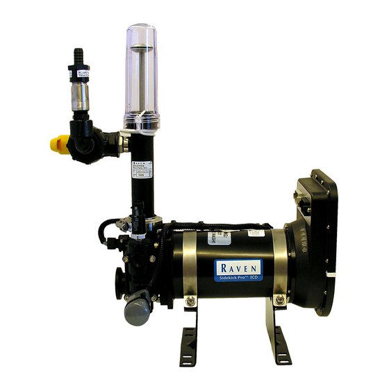
SIDEKICK PRO ICD PUMP SPECIFICATIONS The Raven Sidekick Pro™ ICD injection pump is a positive displacement, variable speed piston pump used for direct chemical injection applications. Pump... -
Page 14: Pump Dimensions
HAPTER PUMP DIMENSIONS FIGURE 2. Pump Enclosure Dimensions 40.13” (101.93 cm) Front 29.75” (29.75 cm) Bottom Mounting Holes 21.37” (54.28 cm) 2.00” (5.08 cm) Side 6.76” (17.17 cm) 8.56” (21.75 cm) 22.48” (57.10 cm) Dry Weight - 200 lbs (90.72 kg) Full Weight (Approximate) - 500 lbs (226.80 kg) Injection Cabinet Installation and Operation Manual... -
Page 15: Mixer Flow Specifications
INTRODUCTION MIXER FLOW SPECIFICATIONS For 36 GPM of water there is approximately a 10 PSI drop. For 36 GPM of fertilizer there is approximately a 20 PSI drop. INTERNAL PLUMBING OVERVIEW FIGURE 3. Internal Cabinet Plumbing Electric Rinse Valves Pump Outlet 3-Way Valve Agitation Pump... -
Page 16: Updates
Updates for Raven manuals as well as several system components are available at: https://ravenprecision.com/ Sign up for e-mail alerts to receive notice when updates for your Raven products are available on the Raven web site. At Raven Industries, we strive to make your experience with our products as rewarding as possible. -
Page 17: Chapter 3 Installation
BEST PRACTICES • The Raven Sidekick Pro™ ICD injection system pumps chemical into the main carrier line at the point of injection. This point must be on the pressure side of the carrier product pump and should be as close to the boom section valves as possible. -
Page 18: In-Line Mixer Mounting
This configuration may help to extend the service life of the flow meter by minimizing flow meter components exposure to corrosive chemicals. IN-LINE MIXER MOUNTING FIGURE 2. Example Sidekick Pro ICD Injection System Contained in Mixer Assembly In-Line Mixer 1. -
Page 19: Plumbing Installation
2. Connect and secure 1/2” reinforced tubing from the pump outlet to the injection point on the installed mixer. VERIFYING INSTALLATION OF THE SIDEKICK PRO™ ICD Before filling the tank with chemical for the first time, thoroughly inspect the chemical supply tank and clean any plastic or metal particles that may be left from the manufacturing or installation process. - Page 20 HAPTER FIGURE 4. Node Mounting ECU Mounting Hole Injection Pump Control ECU Cabling Cabling 2. Locate the injection pump cabling routed out the rear access cutout of the cabinet. 3. Connect the control node cabling to the injection cabinet cabling. 4.
-
Page 21: Calibration And Operation
To access the calibration and diagnostics for a specific injection product: Sidekick Pro ICD Menu Home 1. Open the UT Menu and select the desired Sidekick Pro™ ICD Menu button. 2. Press the Home icon. The following information will display: FIGURE 1. Sidekick Pro™ ICD Main Screen... -
Page 22: Enabling Agitation And Rinse Assist
Sidekick Pro Product Setup System Settings ICD Menu 1. Open the UT Menu and select the desired Sidekick Pro™ ICD Menu icon. 2. Select Product Setup. 3. Select System Settings. 4. Select the Agitator Equipped and Rinse Assist Equipped check boxes. -
Page 23: Sidekick Pro™ Icd System Settings
SideKick Pro ICD Menu Product Setup System Settings 1. Open the UT Menu and select the desired Sidekick Pro™ ICD Menu button. 2. Press the Product Setup button. 3. Select Settings. The following information will display: Calibration and Operation: Sidekick Pro™ ICD Menu... -
Page 24: Current Totals Data
Sidekick Pro Totals Data Current Totals ICD Menu 1. Open the UT Menu and select the desired Sidekick Pro™ ICD menu icon. 2. Select the Totals Data icon then Current Totals. The following information will display: FIGURE 3. Current Totals Display... -
Page 25: Device Totals
Sidekick Pro Totals Data Device Totals ICD Menu 1. Open the UT Menu and select the desired Sidekick Pro™ ICD menu icon. 2. Select the Totals Data icon then Device Totals. The following information will display: TABLE 2. Device Totals Display... -
Page 26: Tests
NOTE: It may required 3 - 5 gallons (11 - 19 liters) of liquid in the chemical tank to ensure the system is primed properly. PRIME THE INJECTION PUMP Sidekick Pro Diagnostics Test ICD Menu 1. Open the hand valve(s) between the supply tank and injection pump so that the valves direct flow from the tank towards the pump. -
Page 27: Catch Test
Also, verify that the product is flowing freely. Cold temperatures and high viscosity products may cause high vacuum pressures and cause the pump to not operate properly. 3. Select the Sidekick Pro™ ICD Menu icon. 4. Select Diagnostics. 5. Select Test. -
Page 28: Demonstration Mode
Also, verify that the product is flowing freely. Cold temperatures and high viscosity products may cause high vacuum pressures and cause the pump to not operate properly. 6. Press the Sidekick Pro™ ICD icon for the desired pump product number. 7. Select Diagnostics. - Page 29 CALIBRATION AND OPERATION VIEW INACTIVE DTC’S Shows the SPN and FMI for all of the inactive DTC’s along with a short description and the number of times the error occurred. Calibration and Operation: Diagnostic Trouble Codes...
- Page 30 HAPTER Injection Cabinet Installation and Operation Manual...
-
Page 31: System Maintenance
S YSTEM MAINTENANCE CHAPTER C H A P T E R 5 Proper injection pump maintenance is critical to maintain system performance and extend the lifetime of the injection pump. Perform these maintenance procedures periodically over a season and be sure to store the pump properly when not being used. -
Page 32: Check Valve O-Rings
3. Examine the valve assembly O-ring and replace if cut or nicked. These o-rings are made of a chemical resistant compound and should only be replaced with O-rings supplied by a local Raven dealer. 4. Disassemble the check valve assemblies as shown in Figure 1 below. - Page 33 SYSTEM MAINTENANCE TABLE 1. Check Valve Assembly Replacement Parts Discharge Valve Assemblies Intake Valve Assemblies Item Description Raven P/N Item Description Raven P/N 107-0171-519 Fitting, Plug Fitting, Plug 107-0171-519 107-0171-955 O-Ring 219-0002-912 O-Ring 219-0002-912 Guide, Poppet 107-0159-934 Retainer, Intake 107-0171-459...
-
Page 34: Pump Cam And Bearing
HAPTER FIGURE 1. Check Valve Assemblies Intake Valve Assembly Discharge Valve Assembly Blue P/N 063-0173-677 P/N 063-0172-504 Spring Retainer White P/N 063-0173-310 (item 3) 1. Push Down 2. Rotate 90° 3. Lift Up Note A Above PUMP CAM AND BEARING CAUTION Chemical residue or build up may be present on internal pump components. -
Page 35: Piston Seal Replacement
The piston seals should be serviced or replaced If chemical begins leaking from the weep hole on the underside of the pump housing. NOTE: New piston seals are supplied in the Pump Seal Kit (P/N 117-0159-987) available through a local Raven dealer. FIGURE 2. Pump Head and Motor Separation FIGURE 3. - Page 36 The seals and o-rings are made of a chemical resistant compound and should only be replaced with O-rings supplied by a local Raven dealer. 7. Inspect the piston for scratches. If the finish is scratched or damaged, replace the piston.
-
Page 37: Returning The Pump For Service Or Repair
Refer to the following procedure should it be necessary to return the Sidekick Pro™ ICD injection pump for service or repairs: 1. Prior to disconnecting the injection pump, drain the chemical tank and rinse with clean water. - Page 38 HAPTER Injection Cabinet Installation and Operation Manual...
-
Page 39: Troubleshooting
C H A P T E R 6 MOTOR CONTROL ECU LED STATUS INDICATORS MOTOR CONTROL ECU LED STATUS INDICATORS The Sidekick Pro™ integrated motor control ECU displays the status of the injection pump with the following ECU status indicators. FIGURE 1. LED Status Indicators... -
Page 40: Diagnostic Trouble Codes
HAPTER TABLE 1. LED Status Indicators Status Display If logic power is present at the motor control ECU, the logic power indicator Logic Power will be on. If high current power is present at the motor control ECU, the high current High Current Power power indicator will be on. - Page 41 There may be debris in the inlet, a plugged filter/ strainer, hand valve turned the wrong directions or obstruction in the outlet of the chemical tank. Injection pump fault Return pump to a local Raven dealer for service. 523189 Invalid pump calibration Adjust the flow correction offset.
- Page 42 HAPTER Injection Cabinet Installation and Operation Manual...
-
Page 43: Chapter 7 Replacement Parts
(has bleed hole, Control identifiable by 046 stamped on flat surfaces) Pump Flow Plumb to Point of Monitor Sensor Injection Check Valve Plumb to Chemical Pump Vacuum Tank for Sensor Recirculation and Priming Replacement Parts: Sidekick Pro™ ICD Injection Module Parts... - Page 44 To replace the pressure transducer: 1. Disable and shutdown any automatic product control features of the Sidekick Pro™ injection system and turn off the vehicle when replacing the pressure transducer assembly. WARNING Hazardous chemicals may be under pressure even if the pump has not been in service recently.
- Page 45 REPLACEMENT PARTS 1. Disable and shutdown any automatic product control features of the Sidekick Pro injection system and turn off the vehicle when replacing the vacuum switch assembly. WARNING Hazardous chemicals may be under pressure even if the pump has not been in service recently.
- Page 46 HAPTER FIGURE 2. Gauge Tool and Flow Monitor Sensor Bracket Alignment Gauge Tool Flow Monitor Sensor LED Light 6. Tighten the two Allen head screws to secure the sensor bracket. NOTE: Leave the gauge tool in place to ensure that the sensor bracket stays properly aligned during the rest of the process.
- Page 47 Discharge Valve, Body O-Ring (Viton) 106-0159-622 219-0002-018 Intake O-Ring (Viton) 219-0002-018 Plug fitting (P/N 107-0171-955) is used with check valve assemblies (P/N 063-0173-310). b. O-Rings included in Pump Seal Kit (P/N 117-0159-987). Replacement Parts: Sidekick Pro™ ICD Injection Module Parts...
-
Page 48: Injection Pump Flow Monitor Sensor
HAPTER FIGURE 4. Check Valve Spring Retainer Assemblies Intake Valve Assembly Discharge Valve Assembly (P/N 063-0173-677) (Left Side - P/N 063-0172-504) (Right Side - P/N 063-0173-310) 1. Press Down 2. Rotate 90° 3. Lift Up INJECTION PUMP FLOW MONITOR SENSOR Perform the following procedure to replace the flow monitor sensor (P/N 063-0173-492). - Page 49 REPLACEMENT PARTS Replacement Parts: Sidekick Pro™ ICD Injection Module Parts...
- Page 50 HAPTER Injection Cabinet Installation and Operation Manual...
-
Page 51: Appendix A Flowcharts
F LOWCHARTS APPENDI X A P P E N D I X A FLOWCHARTS This section provides a flowchart of screens that may be useful during operation. UT HOME SCREEN WITH RINSE ASSIST AND AGITATION ACTIVE Flowcharts: Flowcharts... - Page 52 PPENDIX ICD Tests Screen Flow Injection Cabinet Installation and Operation Manual...
- Page 53 Chemical Handling and Safety Updates Electrical Safety Injection Cabinet Mounting In-Line Mixer Mounting Installation Verifying Sidekick Pro Verifying Installation of the Sidekick Pro Internal Plumbing Maintenance Seasonal Maintenance and Storage Maintenance and Storage Mixer Flow Specifications Overview Injection System Components...
- Page 54 Index Injection Cabinet Installation and Operation Manual...
- Page 55 Bring the defective part and proof of purchase to your Raven dealer. If the dealer approves the warranty claim, the dealer will process the claim and send it to Raven Industries for final approval. The freight cost to Raven Industries will be the customer’s responsibility.
- Page 56 Bring the defective part and proof of purchase to your Raven dealer. If the dealer approves the warranty claim, the dealer will process the claim and send it to Raven Industries for final approval. The freight cost to Raven Industries will be the customer’s responsibility.
Need help?
Do you have a question about the Sidekick Pro and is the answer not in the manual?
Questions and answers