Raven Sidekick Pro Installation And Operation Manual
Can injection for case ih 3/4xxx
Hide thumbs
Also See for Sidekick Pro:
- Installation & operation manual (86 pages) ,
- Installation and operation manual (56 pages) ,
- Quick installation reference (26 pages)

Subscribe to Our Youtube Channel
Related Manuals for Raven Sidekick Pro


Summary of Contents for Raven Sidekick Pro
- Page 1 CAN Sidekick Pro Injection for Case IH 3/4XXX Installation and Operation Manual Manual No. 016-0171-592 Rev. E 12/18 E32359 Copyright 2016...
- Page 2 Raven systems, or products used as components of systems, which rely upon the reception of these signals or availability of these services. Raven Industries accepts no responsibility for the use of any of these signals or services for other than the stated purpose.
-
Page 3: Table Of Contents
........................57 Tank Valve Operation ......................57 Fill Station .......................... 58 Pump Valves ........................58 Recirculation Valves ......................59 Chapter 5 Viper 4 (ROS) Initial Set-Up..........61 Raven OS Setup ........................61 Section Setup ........................61 Manual No. 016-0171-592 Rev. E... - Page 4 ............................. 80 Chapter 8 Replacement Parts ............... 83 Replacement Parts ........................83 Chapter 9 System Diagrams ..............87 Electrical ..........................87 Injection Pump ........................90 Plumbing ..........................91 CAN Sidekick Pro Injection for Case IH 3/4XXX Installation and Operation Manual...
-
Page 5: Chapter 1 Important Safety Information
• Follow all safety information presented within this manual. • If you require assistance with any portion of the installation or service of Raven equipment, contact a local Raven dealer for support. • Follow all safety labels affixed to system components. Be sure to keep safety labels in good condition and replace any missing or damaged labels. -
Page 6: Instructions For Wire Routing
• Wiring should be protected or shielded if it needs to route near hot temperatures beyond harness component specifications Harnessing should not have sharp bends. CAN Sidekick Pro Injection for Case IH 3/4XXX Installation and Operation Manual... -
Page 7: Instructions For Hose Routing
IMPORTANT SAFETY INFORMATION Allow sufficient clearance from machine component operational zones such as: • Drive shafts, universal joints and hitches (i.e. 3-point hitch) • Pulleys, gears, sprockets • Deflection and backlash of belts and chains • Adjustment zones of adjustable brackets •... - Page 8 • Tree limbs, brush and debris • Damage where service personnel or operators might step or use as a grab bar • Damage when passing through metal structures • High pressure wash CAN Sidekick Pro Injection for Case IH 3/4XXX Installation and Operation Manual...
-
Page 9: Chapter 2 Introduction
Using a separate injection module, or tank, eliminates mixing chemicals and reduces chemical waste, and simplifies equipment care and maintenance. Sidekick Pro provides connectivity to a Raven CANbus system to allow an existing Raven CAN control console to control the rate of the chemical injection system. -
Page 10: Required Components
REQUIRED COMPONENTS The following components must be installed with the Sidekick Pro: • Raven OS Version 2.1.5.32 for the Viper 4 Console or Pro 700 Console Software Version 30. TOOLS AND MATERIALS NEEDED The following tools are recommended for completing the installation: •... -
Page 11: Updates
INTRODUCTION UPDATES Raven software and documentation updates may be made available periodically on the Raven Applied Technology web site: www.ravenhelp.com At Raven Industries, we strive to make your experience with our products as rewarding as possible. One way to improve this experience is to provide us with feedback on this manual. - Page 12 HAPTER CAN Sidekick Pro Injection for Case IH 3/4XXX Installation and Operation Manual...
-
Page 13: Installation
C H A P T E R 3 INSTALLATION PREPARATION Verify Software version 2.1.5.32 or higher is present on the Raven Viper 4, or that Version 30 or higher is present on the Case IH Pro 700 controller if equipped. - Page 14 3/4” hole in the location shown on both sides of the machine. For 32XX machines that do not have support tabs present, weld-on tabs have been provided. CAN Sidekick Pro Injection for Case IH 3/4XXX Installation and Operation Manual...
- Page 15 INSTALLATION FIGURE 5. Lower Support Tab Hole Location Inner Plate Axle 3.724” 1.25” 6. Clamp the template to the existing lower support bracket as shown below. Note the distance from the axle and tower support to the hole location. FIGURE 6. Weld-On Support Tab Position Axle Inner Plate Template Hole...
- Page 16 There must be at least 1” of clearance alongside the parallel link arms to accommodate the tank and tank cage mounting. 1. Locate the hose guide hoops (if present) on the side of the right hand parallel link arm. CAN Sidekick Pro Injection for Case IH 3/4XXX Installation and Operation Manual...
- Page 17 INSTALLATION FIGURE 9. Stock Carrier Hose Guide Hoops Cut Hoops Off Next to Parallel Link Arm 2. Cut the hoops off as near to the parallel link arms as possible. NOTE: The hoops will be reused. 3. Weld the hoops to the top side of the parallel link arm in the position shown below. NOTE: Protect the hood and hose from cutting debris or weld spatter.
- Page 18 FIGURE 12. Fully Extended Axles Fully Extended 8. At the rear mud shields, loosen hydraulic hose fastener clamps for rear wheel drive motor hoses. FIGURE 13. Drive Motor Hose Clamps Hose Clamps CAN Sidekick Pro Injection for Case IH 3/4XXX Installation and Operation Manual...
- Page 19 INSTALLATION 9. Pull excess slack in hose through clamps (there may be 4” or more), towards the front of the machine. Ensure the hose does not obstruct tire operation. FIGURE 14. Drive Motor Hoses with Slack Removed Slack Pulled Through Clamps Towards Front Axle 10.
-
Page 20: Installation
FIGURE 16. Pump Station Installation Frame Fastener 3/8” Bolts Plates 6” for 32xx Machines (107-0172-339) 8” for 33xx, and 4XXX Machines Battery Box Pump Station (116-0159-765) CAN Sidekick Pro Injection for Case IH 3/4XXX Installation and Operation Manual... - Page 21 INSTALLATION FIGURE 17. Installed Pump Station Hardware 3/8” Bolt, Nyloc Nut, Spacer, and Washers Frame Fastener Plates (107-0172-339) Pump Station (116-0159-765) 2. While facing the pump inlet, rotate the pump mounting bracket 90° counter clockwise for pump 1, clockwise for pump 2 (optional). FIGURE 18.
- Page 22 The strainer may need to be rotated slightly.) 5. Install the pump shield on the pump station using 3/8” - 16 x 1-1/4” bolts and 3/8” washers. CAN Sidekick Pro Injection for Case IH 3/4XXX Installation and Operation Manual...
- Page 23 INSTALLATION FIGURE 21. Pump Shield Installed INDUCTOR STANDOFF BRACKET INSTALLATION (4XXX MACHINES) 1. Loosen and remove the lock nuts securing the inductor. 2. Remove the inductor. 3. Use the existing U-bolt and lock nuts to install and secure the inductor standoff bracket. Torque the lock nuts to 130 lb-ft.
- Page 24 3/8” - 16 x 6” or 8” bolts, 3/8” washers, 3/8” spacers, and 3/8” nyloc washers. NOTE: Install the bolts so that the spacers and nuts are toward inside of the machine frame to clear plumbing component installation. CAN Sidekick Pro Injection for Case IH 3/4XXX Installation and Operation Manual...
-
Page 25: Tank Support Bracket Installation
INSTALLATION FIGURE 25. Fill Station Installed Frame Fastener Plate (107-0172-339) Fill Station (116-0159-772) Platform 3/8” Bolts TANK SUPPORT BRACKET INSTALLATION UPPER SUPPORT ARM INSTALLATION 1. Install the left and right upper support arm into the upper cross tubes. Align the holes in the cross tubes with threaded holes in the upper support arm. - Page 26 3. Secure the upper support arm to the upper cross tubes using the provided 5/8” washers, 5/8” spacers, and 5/ 8” bolts with the thread locking compound. Tighten the bolts to 130 ft-lbs. CAN Sidekick Pro Injection for Case IH 3/4XXX Installation and Operation Manual...
- Page 27 INSTALLATION FIGURE 28. Installed Support Arm and Hardware UPPER TANK SUPPORT INSTALLATION 1. Secure the left and right upper tank support to the upper support arm using the provided 5/8” washers, 5/8” - 11 x 2” bolts with thread locking compound. Tighten the bolts to 130 ft-lbs. FIGURE 29.
- Page 28 1. Secure the stiffener rods to the upper and lower tank support using the provided 5/8” washers (two per bolt), 5/8” - 11 x 2” bolts, and 5/8” nyloc nuts. CAN Sidekick Pro Injection for Case IH 3/4XXX Installation and Operation Manual...
- Page 29 INSTALLATION FIGURE 32. Stiffener Rod Installed Install Both Stiffener Rods so Support Arm is Closer to Inside of Stiffener Rod Machine (107-0172-378) SAFETY DECAL PLATE AND REFLECTOR INSTALLATION 1. Secure the safety decal plate to the lower support using 5/8” - 11 x 2” bolts, 5/8” washers (two per bolt), and 5/ 8”...
-
Page 30: Mixer Installation
Place the mixer so that the inlet check valve is on the right side of the machine with the center of the mixer approximately 4” right of the center boom. CAN Sidekick Pro Injection for Case IH 3/4XXX Installation and Operation Manual... -
Page 31: Plumbing Mixer Assembly
INSTALLATION FIGURE 36. Mixer Installed 3/8” U-Bolts (length varies by boom length) 3” Mixer and Check Valve Assembly P/N 063-0173-698 Center of Mixer (approximately 4” right of center of boom section) PLUMBING MIXER ASSEMBLY PLUMBING MIXER ASSEMBLY 1. Measure and cut the current supply hose approximately 36” from the end. Installation: Installation... - Page 32 1/4” Gauge Port (Should Face Away M220 Clamp (1) from Boom) and M220 Gasket (1) Installed Mixer and Check Valve M300 Clamp (3) Assembly and M300 Gasket (3) CAN Sidekick Pro Injection for Case IH 3/4XXX Installation and Operation Manual...
- Page 33 INSTALLATION FIGURE 39. Mixer Outlet Plumbing Installed M300 to M220 M220 Clamp (1) and Reducing Coupling M220 Gasket (1) M300 Sweep Elbow 1-1/2” Hose Barb to M220 (1) or 2” Hose Barb to M220 (1) 1-1/2 to 3” Hose Clamp Hose to Boom Plumbing M300 Clamp (3)
- Page 34 6. Secure the hose to the fitting with the provided hose clamps. TANK OVERFLOW PLUMBING 1. Install the M100 gasket between the 1” hose barb and the 1” NPT to M100 and secure assembly with a M100 clamp. CAN Sidekick Pro Injection for Case IH 3/4XXX Installation and Operation Manual...
- Page 35 INSTALLATION 2. Seal threaded joints with the provided thread sealing compound. Thread each Tank Overflow plumbing assembly on to the 1” overflow port on the top of each tank. Point the hose barb elbow towards the rear corner of the tank cage installed on the machine missing the agitator hole. FIGURE 43.
-
Page 36: Dual Pump Station Plumbing Installation
1. Assemble the dual pump fittings as shown in the image below. Seal all threaded joints with the provided pipe thread sealant. NOTE: Attach valves to the strainer so the strainer cap can be removed. CAN Sidekick Pro Injection for Case IH 3/4XXX Installation and Operation Manual... - Page 37 INSTALLATION FIGURE 46. Dual Pump Fitting Assembly M100 Connect to Pump Inlet 1/2” NPT Clamp 1/2” FNPT to M100 Pipe Nipple 12/” NPT Check M100 to 1/2” 1” Hose Valve Barb to M100 1/2” NPT Street 3/4” Elbow 1/2” NPT M100 Gasket Check Pipe Nipple...
-
Page 38: Single Pump Station Plumbing Installation
Hose Barb Elbow SINGLE PUMP STATION PLUMBING INSTALLATION 1. Assemble the single pump fittings as shown in the image below. Seal all the threaded joints with pipe thread sealant. CAN Sidekick Pro Injection for Case IH 3/4XXX Installation and Operation Manual... - Page 39 INSTALLATION FIGURE 49. Single Pump Fitting Assembly The assembly in the box is mounted to the valve mounting bracket that doesn’t have a pump mounted above. 1/2” NPT to 3/4” Hose Barb Elbow 1” Hose 3/4” Hose Barb to Clamps M100 3/4”...
-
Page 40: Rinse Plumbing Installation
1. Apply the provided thread sealant to all threaded joints. 2. Locate the 1-1/4” rinse tank supply hose under the cab behind the front axle for 3XXX machines, or behind the main solution tank for 4XXX machines. CAN Sidekick Pro Injection for Case IH 3/4XXX Installation and Operation Manual... - Page 41 INSTALLATION 3. Cut the rinse tank supply hose in the locations shown for each machine type. FIGURE 53. Cut Location (3XXX Machines) Cut Location (approximately 4” to right of existing tee) FIGURE 54. Cut Location (4XXX Machines) Cut Location 4. Assemble the rinse tank hose tee fitting as shown below. Installation: Installation...
- Page 42 5. Install the tee at the cut location and secure the tee to the hose using four 1-1/4” hose clamps. FIGURE 56. Rinse Tank Tee Installed (3XXX Machines) Rinse Tank Tee 6. Assemble the rinse tank drain valve as shown below. CAN Sidekick Pro Injection for Case IH 3/4XXX Installation and Operation Manual...
- Page 43 INSTALLATION FIGURE 57. Assembled Rinse Tank Drain Valve Fittings (3XXX Machines) 3/4” NPT Elbow 3/4” NPT Plug 3/4” Selector Valve 3/4” NPT to 3/4” Hose Barb FIGURE 58. Assembled Rinse Tank Drain Valve Fittings (4XXX Machines) 3/4” NPT Plug 3/4” NPT Elbow 3/4”...
- Page 44 The dual pump station rinse tee will be installed later. FIGURE 60. Dual Pump Station Rinse Tee Assembly 1/2” NPT Tee 3/4” Hose Barb to 1/2” 1/2” NPT to 3/4” Hose Barb Elbow CAN Sidekick Pro Injection for Case IH 3/4XXX Installation and Operation Manual...
-
Page 45: Fill Station Plumbing Installation
INSTALLATION FILL STATION PLUMBING INSTALLATION 1. Assemble the valve assembly as shows in the images below. Apply the provided thread sealant to all threaded joints. FIGURE 61. Tank 2 (Front) Fill Station Valve Assembly 3/4” NPT to 1” Hose To Pump Station Fill Valve Barb Elbow M100 to 1”... - Page 46 Do not over tighten as it will damage the valve. FIGURE 64. Installed Coupler Assembly NPT Hose Barb Elbow Valve Assembly Clamping U-Bolt M100 Clamp and M100 Gasket Coupler Fill Station Assembly (116-0159-772) CAN Sidekick Pro Injection for Case IH 3/4XXX Installation and Operation Manual...
-
Page 47: Hose Routing
INSTALLATION HOSE ROUTING TANK HOSES 1. Connect one end of the supplied 1” braided hose to the hose barb fitting on the tank drain valve plumbing at the bottom of the tank. FIGURE 65. Tank Hose Routing Route Tank Drain Hose Through Tank Support Brackets, Under... -
Page 48: Tank Overflow Hoses
TANK OVERFLOW HOSES 1. Connect one end of the supplied 1” braided hose to the hose barb fitting on the tank overflow plumbing at the top of the tank. CAN Sidekick Pro Injection for Case IH 3/4XXX Installation and Operation Manual... - Page 49 INSTALLATION FIGURE 68. Tank Overflow Hose Routing 1. Route the hose down the side of the tank cage support brackets. 2. Secure the hose to the tank cage and brackets with the provided cable ties. 3. Cut the hose so it exhausts slightly below the machine axle and fluid will not contact the frame. FILL STATION 1.
- Page 50 4. Secure the hose to the hose barb using two of the provided hose clamps. Connect the other remaining open end of the hose to the open 3/4” port on the rinse hose tee fitting. CAN Sidekick Pro Injection for Case IH 3/4XXX Installation and Operation Manual...
- Page 51 INSTALLATION FIGURE 71. Installed and Secured Hose (3XXX Machines) Rinse Hose Tee Dual Pump Station Rinse Tee (not used for single pump station) Rinse Tank Shutoff Valve FIGURE 72. Installed Rinse Valve Assembly (4XXX Machines) NOTE: 4XXX rinse valve assembly is secured to the fill station using the existing fill station u-bolt clamp. 5.
- Page 52 Approximately 4’ from Pump Station Guard Sleeve NOTE: On 4XXX machines, route the dual pump station rinse tee and hoses across the frame to the rinse valve attached to the fill station. CAN Sidekick Pro Injection for Case IH 3/4XXX Installation and Operation Manual...
- Page 53 INSTALLATION 12. Use strips of nylon hose guard sleeve to protect the hose from sharp edges. Secure the hose guard sleeve to the hose using provided cable ties. PUMP OUTLET TO CHEMICAL INJECTION POINT PLUMBING 1. Apply the provided thread sealant to all threaded joints. 2.
- Page 54 3. Route the hose around the front of the engine compartment, following the installed hoses, to Tank 1. 4. Connect the hose to 1/2” hose barb tank recirculation port on the top of the tank. Secure with a hose clamp. CAN Sidekick Pro Injection for Case IH 3/4XXX Installation and Operation Manual...
- Page 55 INSTALLATION FIGURE 78. Injection Tank Ports Overflow Port Recirculation Port FIGURE 79. Recirculation Hose Routing Hoses from Pump 1 Recirculation Port to Hoses from Pump 2 Tank 1 Recirculation Recirculation Port to Port Should be Secured Tank 2 Recirculation to Tank and Fill Hoses Port Should be Around the Front of the Secured to existing...
-
Page 56: Electrical Components
5. Connect Pump 1 and Pump 2 connections to the supplied injection pump cables for each pump. Keep the connection capped if pump 2 is not used. 6. Connect the power wires (red) on the supplied chassis harness to the machine fuse panel power strip connections. CAN Sidekick Pro Injection for Case IH 3/4XXX Installation and Operation Manual... -
Page 57: Decal Placement
INSTALLATION 7. Install the supplied 30 Amp bolt down fuses to connect the previously connected chassis power cables to positive side of the high current power strip. 8. Connect the connectors on the CAN injection pump harness to the corresponding open connectors on the injection pump. - Page 58 HAPTER FIGURE 84. Tank Valve Operation Decals Tank Valve Operation Decal (bottom rear of both tank support CAN Sidekick Pro Injection for Case IH 3/4XXX Installation and Operation Manual...
-
Page 59: Chapter 4 Valve Operation
V ALVE OPERATION CHAPTER C H A P T E R 4 VALVE OPERATION This section provides basic steps for operating the pump, fill station, and recirculation valves. TANK VALVE OPERATION FIGURE 1. Tank Valve Operation Each tank valve can be set to drain/off (arrow left), off (arrow up), or pump fill (arrow right). Valve Operation: Valve Operation... -
Page 60: Fill Station
FIGURE 3. Single Pump Valve Dual pumps have two valves on each pump. One valve switches between the tank or the boom, the second valve is for selecting pump or drain. CAN Sidekick Pro Injection for Case IH 3/4XXX Installation and Operation Manual... -
Page 61: Recirculation Valves
VALVE OPERATION FIGURE 4. Dual Pump Valve RECIRCULATION VALVES If the sprayer has a single pump, there will be two valves. One valve will select the which chemical tank is being used. The second valve opens or closes the rinse tank. FIGURE 5. - Page 62 HAPTER FIGURE 6. Dual Recirculation Valve CAN Sidekick Pro Injection for Case IH 3/4XXX Installation and Operation Manual...
-
Page 63: Viper 4 (Ros) Initial Set-Up
Once installation of the injection system has been verified, and the motor control node is recognized by the Raven OS device, the Sidekick Pro and display device must be calibrated to provide accurate control of the injected product. If more than one SideKick Pro is installed, the product nodes will have to be addressed in the correct order. -
Page 64: Product Settings Tab
Set Application Type to Liquid Injection. The application type should automatically be set to liquid injection when ROS detects a Sidekick Pro injection system. Refer to the injection system troubleshooting information or contact a local Raven dealer for additional assistance if the liquid injection option is not available for the application type. -
Page 65: Injection Tab
Set Motor Cal. Set the motor cal (valve cal) value to 123. Set Motor Cal 2. Set the motor cal 2 (valve cal 2) to 5054. INJECTION CALIBRATION TAB Refer to Sidekick Pro™ Injection Pump Priming and Calibration section on page 66 for injection pump calibration. PRESSURE SETTINGS TAB PRESSURE SETTINGS... - Page 66 Pressure Cal 1. Set pressure cal 1 (pump outlet pressure) to zero. Ensure no pressure is on outlet of injection pump or in the injection lines. When connected to a Sidekick Pro motor control node, the pressure cal 1 value will display the pressure at the outlet port of the injection pump.
-
Page 67: Section Settings Tab
VIPER 4 (ROS) INITIAL SET-UP 2. Select the Pressure 1 Cal value and enter a value of zero to calibrate for ambient conditions. 3. Retighten the outlet valve cartridge before resuming normal operations. Pressure Cal 2. Not used. NOTE: To monitor carrier or boom pressure, a pressure transducer may be installed and connected to the carrier product control channel. -
Page 68: Sidekick Pro™ Injection Pump Priming And Calibration
NOTE: The range for the FER error cal is 0 through 9. The default value for a Sidekick Pro injection pump is 6. Enable Maximum Vacuum Error. Enable the vacuum error to provide an alert to the operator if the injection pump cannot draw product from the chemical supply tank. -
Page 69: Pump Priming And Calibration Procedures
68 for details on calibrating the Sidekick Pro injection pump. PRIME PUMP Touch the Prime button to begin priming the Sidekick Pro injection pump. Refer to Prime the Injection Pump section on page 68 for assistance with priming the Sidekick Pro injection pump. -
Page 70: Prime The Injection Pump
If the console displays an error message during the priming process, verify that the conditions listed in step 4 are present. If the problem continues, refer to the Sidekick Pro Calibration and Operation Manual for assistance with addressing issues during the pump priming process. - Page 71 Check screens, hose diameter and any hand valves between the chemical tank and pump inlet. Also, verify that the product is flowing freely. Cold temperatures and low viscosity products may cause high vacuum pressures and cause the pump not to operate properly. Viper 4 (ROS) Initial Set-Up: Sidekick Pro™ Injection Pump Priming and Calibration...
- Page 72 5% from the value printed on the pump housing, perform pump maintenance procedures outlined in the Sidekick Pro Calibration and Operation Manual. If the problem persists, troubleshoot the injection system, for possible solutions to issues with the injection pump.
-
Page 73: Cnh Pro 700 Set-Up
C NH PRO 700 SET-UP CHAPTER C H A P T E R 6 RE-ADDRESSING RATE CONTROLLERS The re-address process determines which control windows are reporting windows correspond to each rate controller in the direct injection system. Use the Re-Address Rate Controllers screen to establish a new address for each rate controller on the CAN bus: •... - Page 74 Product Controller Setup screen. 3. Configure the display to match the settings and equipment on the Product Controller Setup screen. NOTE: This information is required to operate the sprayer control. CAN Sidekick Pro Injection for Case IH 3/4XXX Installation and Operation Manual...
- Page 75 CNH PRO 700 SET-UP Configuration Screen Settings TABLE 1. Setting Description Additional Information At a minimum, the main tank controller must be set. If the sprayer is equipped with a direct injection system, enter the rate controller settings for each direction injection tank.
-
Page 76: Alarms Set-Up
1. On the home screen, press the Toolbox icon . This will open the Toolbox screens. 2. Press the Alarms icon to display the Alarm Setup screen. Set the following: CAN Sidekick Pro Injection for Case IH 3/4XXX Installation and Operation Manual... - Page 77 CNH PRO 700 SET-UP Alarms Set-Up TABLE 2. Setting Description Additional Information Set the alarms for the main tank. If the sprayer is equipped with a direct injection system, enter the alarm settings for each direct injection tank. Press the Rate Controller window to access the pop-up window available options: Use the Rate Controller •...
-
Page 78: Pressure Transducer Calibration
The AFS Pro 700 display provides a remote closed-system calibration procedure for the injection pump in a direct injection system. NOTE: Verify your settings on the Product Controller Setup screen before continuing. CAN Sidekick Pro Injection for Case IH 3/4XXX Installation and Operation Manual... -
Page 79: Prime The Injection Pump
CNH PRO 700 SET-UP PRIME THE INJECTION PUMP You must prime the injection pump before you perform the calibration procedure. 1. Open the hand valves between the supply tank and the injection pump. 2. Set the hand valve on the injection pump outlet, if present, to recirculate the product to the supply tank. 3. - Page 80 If the black ring on the calibrator plunger is between the horizontal markings on the pump calibrator cover, the current flowmeter calibration value is appropriate. CAN Sidekick Pro Injection for Case IH 3/4XXX Installation and Operation Manual...
-
Page 81: Chapter 7 Troubleshooting
CHAPTER C H A P T E R 7 MOTOR CONTROL NODE LED STATUS INDICATORS The Sidekick Pro integrated motor control node displays the status of the injection pump with the following node status indicators. FIGURE 1. LED Status Indicators... -
Page 82: Alarms
• Dilute product in chemical supply tank. Some • Chemical too thick chemicals may not be applied using a direct injection system. CAN Sidekick Pro Injection for Case IH 3/4XXX Installation and Operation Manual... - Page 83 Motor/Encoder • Check motor connections. If these connections Alarm • Pump motor or appear secure, return pump to a local Raven dealer for encoder issue service. • Injection node not • Verify high current breaker is not tripped.
- Page 84 HAPTER CAN Sidekick Pro Injection for Case IH 3/4XXX Installation and Operation Manual...
-
Page 85: Chapter 8 Replacement Parts
Flow Sensor 063-0173-492 47465969 Intake Check Valve 063-0172-677 84386870 Calibrator Cover 106-0159-637 47839104 Cable, Sidekick Pro, Gen II, with Agitation Pump Flush 115-0173-191 47839110 Cable, Chassis, Injection, Case 115-0172-233 47839111 Cable, 5’, Extension, AIM Pro Pressure Transducer, Case 115-0172-319 47926573 Injection Cable, 6’... - Page 86 32/33/44XX Label, Sidekick Pro Injection Plumbing Operation, Case IH 037-0159-068 47839161 32/33/44XX Label, Injection, Plumbing Operation, Fill Station 039-0159-069 47839162 Label, Injection, Plumbing Operation, Tank Drain 039-0159-070 47839163 CAN Sidekick Pro Injection for Case IH 3/4XXX Installation and Operation Manual...
- Page 87 REPLACEMENT PARTS Raven Item Description Part Number Part Number Label, Injection, Plumbing Operation, Single Pump Mixer/ 039-0159-071 47839164 Drain Label, Injection, Plumbing Operation, Single Pump Chem/ 039-0159-072 47839165 Rinse Reflector, Pressure Sensitive, Red 041-0159-780 311863A1 Reflector, Pressure Sensitive, Orange 041-0159-781 311865A1 FIGURE 1.
- Page 88 HAPTER CAN Sidekick Pro Injection for Case IH 3/4XXX Installation and Operation Manual...
-
Page 89: Chapter 9 System Diagrams
S YSTEM DIAGRAMS CHAPTER C H A P T E R 9 ELECTRICAL Drawings start on next page. System Diagrams: Electrical... - Page 90 HAPTER FIGURE 1. Dual Pump System Diagram CAN Sidekick Pro Injection for Case IH 3/4XXX Installation and Operation Manual...
- Page 91 SYSTEM DIAGRAMS FIGURE 2. Single Pump System Diagram System Diagrams: Electrical...
-
Page 92: Injection Pump
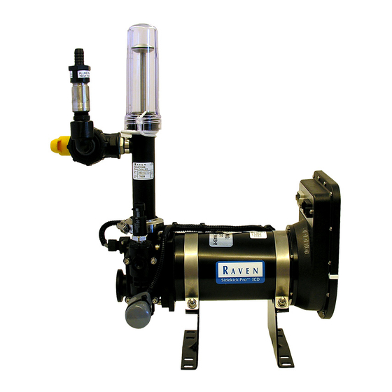
HAPTER INJECTION PUMP FIGURE 3. Injection Pump CAN Sidekick Pro Injection for Case IH 3/4XXX Installation and Operation Manual... -
Page 93: Plumbing
SYSTEM DIAGRAMS PLUMBING FIGURE 4. Dual Pump Injection Plumbing System Diagrams: Electrical... - Page 94 HAPTER FIGURE 5. Single Pump Injection Plumbing CAN Sidekick Pro Injection for Case IH 3/4XXX Installation and Operation Manual...
- Page 95 Index Numerics 22XX with Foamer Attachment Attaching the Lower Tank Support to the Machine Attaching the Tank Support and Tank to the Machine (22XX) Attaching Upper Support Arm to Machine Fill Station Installation Mixer Mixer Installation for 3/4XXX 120’ Boom or 22XX) Overview Injection System Components 7...
- Page 96 Index CAN Sidekick Pro Injection for Case IH 3/4XXX Installation and Operation Manual...
- Page 97 Bring the defective part and proof of purchase to your Raven dealer. If the dealer approves the warranty claim, the dealer will process the claim and send it to Raven Industries for final approval. The freight cost to Raven Industries will be the customer’s responsibility.
- Page 98 Bring the defective part and proof of purchase to your Raven dealer. If the dealer approves the warranty claim, the dealer will process the claim and send it to Raven Industries for final approval. The freight cost to Raven Industries will be the customer’s responsibility.
Need help?
Do you have a question about the Sidekick Pro and is the answer not in the manual?
Questions and answers