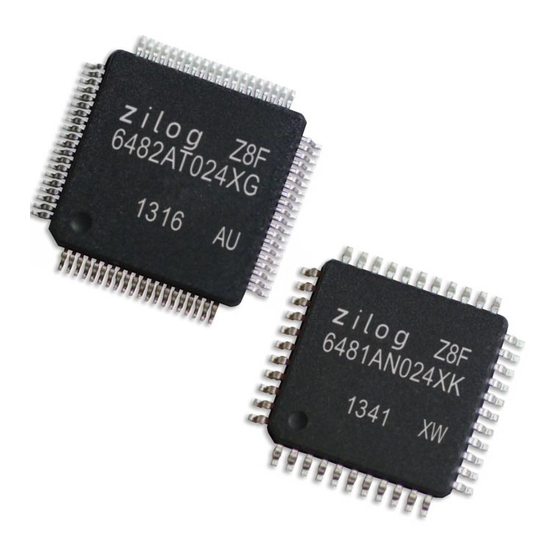
Summary of Contents for ZiLOG Z8 Encore! XP F64 Series
- Page 1 ® Z8 Encore! XP F64xx Series Flash Microcontrollers In-Circuit Emulator User Manual UM016804-0208 ® Copyright ©2008 by Zilog , Inc. All rights reserved. www.zilog.com...
- Page 2 In-Circuit Emulator User Manual Revision History Each instance in the Revision History table reflects a change to this docu- ment from its previous revision. For more details, refer to the correspond- ing pages and appropriate links in the table below. Revision Page Date...
-
Page 3: Table Of Contents
In-Circuit Emulator User Manual Table of Contents Introduction ..........1 Kit Contents . -
Page 4: Introduction
In-Circuit Emulator User Manual Introduction ® The Zilog Z8 Encore! XP F64xx Series In-Circuit Emulator (ICE) pro- ® vides Z8 Encore! XP F64xx Series MCU emulation with a trace and event system for program debugging using ZDS II development tools. -
Page 5: Requirements
In-Circuit Emulator User Manual Requirements Table 1 lists the PC requirements for running ZDS II. Table 1. ZDS II System Requirements Recommended Configuration Minimum Configuration • PC running MS Windows XP, SP1 • PC running MS Windows 98SE/WinNT 4.0– • Pentium III/500 MHz processor SP6/Win2000–SP3/WinXP–SP1 •... - Page 6 In-Circuit Emulator User Manual installing the package adapter that came with your kit into the compatible ® socket on a target board such as the Z8 Encore! XP F64xx Series Devel- opment Board; connecting the emulator to a PC; and connecting the emu- lator to the target.
- Page 7 5). If either power LED fails to illuminate, or if the ICE Fail LED either blinks continuously or fails to extinguish after 15 seconds, there is a problem with the unit. Contact Zilog support at http://www.zilog.com/ for a replacement unit.
- Page 8 In-Circuit Emulator User Manual Target POD and Adapter Assembly ® Figure 3. Connecting the Z8 Encore! XP F64xx Series ICE to the Target POD and Adapter Assembly (Typical Connection Shown) Pin 1 Pin 1 Unit Front ® Figure 4. Z8 Encore! XP F64xx Series ICE Top View UM016804-0208...
-
Page 9: Configure The Hardware
In-Circuit Emulator User Manual ICE Run ICE Fail J11 and J14 J10 and J2 ® Figure 5. Z8 Encore! XP F64xx Series ICE Front-Panel Configure the Hardware ® Configuring the Z8 Encore! XP F64xx Series ICE consists of selecting emulator jumper options and setting up Ethernet communications between the emulator and your PC. - Page 10 In-Circuit Emulator User Manual F64xx Series ICE, you must either change the PC’s Ethernet settings to ® match those of the Z8 Encore! XP F64xx Series ICE or vice versa. If using the PC in a stand-alone configuration, set the PC’s IP address to 192.168.1.21 and its subnet mask to 255.255.255.0.
- Page 11 In-Circuit Emulator User Manual Figure 6. The Network Dialog Box 2. In the panel labeled LAN or High-Speed Internet, double-click the Local Area Connection icon. The Local Area Connection Status dia- log box appears (Figure UM016804-0208...
- Page 12 In-Circuit Emulator User Manual Figure 7. The Local Area Connection Status Dialog Box 3. In the Local Area Connection Status dialog box, click the Properties button. The Local Area Connection Properties dialog box appears (Figure UM016804-0208...
- Page 13 In-Circuit Emulator User Manual Figure 8. The Local Area Connection Properties Dialog Box 4. In the panel labeled This connection uses the following items:, select the Internet Protocol (TCP/IP) item to highlight it, and click the Prop- erties button. The Internet Protocol (TCP/IP) Properties dialog box appears (Figure UM016804-0208...
- Page 14 In-Circuit Emulator User Manual Figure 9. The Internet Protocol Properties Dialog Box 5. Enter values for the IP address and subnet mask to match those shown in Figure 4. Leave any remaining fields blank. In this example, an IP address of 192.168.1.21 and a subnet mask of 255.255.255.0 are being assigned to the PC.
- Page 15 In-Circuit Emulator User Manual ® Changing Z8 Encore! XP F64xx Series ICE Settings to Match the PC ® 1. Connect the PC serial port to the Z8 Encore! XP F64xx Series ICE serial port using the DB9-to-DB9 serial cable. 2. Launch HyperTerminal on the PC by selecting Start --> Programs --> Accessories -->...
- Page 16 In-Circuit Emulator User Manual Zilog TCP/IP Software Suite v1.1 Copyright (C) 2003 Zilog Inc. All Rights Reserved clock enabled IP Address: 192.168.1.50 IP Subnet: 192.168.1.0/255.255.255.0 IP Gateway: 192.168.1.254 Z8 Encore! ICE Communication Module 1.0 Copyright © 2001-2003 Zilog, Inc. All Rights Reserved.
-
Page 17: Running A Sample Project
The sample project ice- demo.pro is included in the ZDS II sample directory, located in: c:\Program Files\ZiLOG\ZDSII_<product>_<version> \samples\<processor type>_<demo name> ® Start ZDS II for the Z8 Encore! XP... - Page 18 In-Circuit Emulator User Manual The following procedures require that the emulator be connected Note: to a target board, such as the Z8 Encore! F64xx Series Develop- ment Board. 1. Select File --> Open Project--> c:\Program Files\ZDSII_Z8Encore!_F642X_Emulator_4.6.x\sam- ples\FZ8F642x_ICEDemo\src \icedemo.pro. 2. Double-click main.c in the Project Files window. 3.
-
Page 19: Running A Simple Trace
In-Circuit Emulator User Manual 8. Select the appropriate clock frequency or enter the clock frequency in the Other field. This should match the 20-MHz Clock Oscillator on Y4 of the emulator. Note: The emulator clock cannot be supplied from the Target application Board. -
Page 20: Using Events To Start And Stop A Trace
In-Circuit Emulator User Manual Using Events to Start and Stop a Trace 1. Now we’ll define a pair of events to automatically start and stop a trace. Use this feature, for example, to trace execution of a particular module in your program and see the context in which the module is running with respect to other program modules.


Need help?
Do you have a question about the Z8 Encore! XP F64 Series and is the answer not in the manual?
Questions and answers