Fri-Jado Bake Star intelligent BS3i Service Manual
Hide thumbs
Also See for Bake Star intelligent BS3i:
- Service manual (49 pages) ,
- User manual (36 pages) ,
- Service manual (25 pages)
Table of Contents
Advertisement
SERVICE MANUAL
Bake Star intelligent
MODELS
BS3i
BS5i
BS8i
BS10i
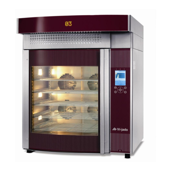
Model BS5i
- NOTICE -
This manual is prepared for the use of trained Service Technicians and should
not be used by those not properly qualified. If you have attended a training
for this product, you may be qualified to perform all the procedures in this
manual.
This manual is not intended to be all encompassing. If you have not attended a
training for this product, you should read, in its entirety, the repair procedure
you wish to perform to determine if you have the necessary tools, instru-
ments and skills required to perform the procedure. Procedures for which you
do not have the necessary tools, instruments and skills should be performed
by a trained technician.
Reproduction or other use of this Manual, without the express written consent of
Fri-Jado, is prohibited.
Service Manual Bake Star intelligent
form 9123665 rev. 06/2013
WWW.FRIJADO.COM
PKII
Advertisement
Table of Contents
Troubleshooting

Related Manuals for Fri-Jado Bake Star intelligent BS3i


Summary of Contents for Fri-Jado Bake Star intelligent BS3i
- Page 1 Reproduction or other use of this Manual, without the express written consent of Fri-Jado, is prohibited. Service Manual Bake Star intelligent form 9123665 rev. 06/2013 WWW.FRIJADO.COM...
- Page 2 TABLE OF CONTENTS EMPTY PAGE Service Manual Bake Star intelligent form 9123665 rev. 06/2013 Page 2 PKII...
- Page 3 TABLE OF CONTENTS Versions Version Issue date Remarks dd/mm/yy 0705 01/05/2007 First release BSi with i-control 0808 01/08/2008 A few errors removed from the partslist. 1301 31/01/2013 Extension with service procedures Extension with electrical tests Expansion of the exploded views. Fasteners included. Included exploded view of extraction hoods.
-
Page 4: Table Of Contents
TABLE OF CONTENTS INDEX Index ................................4 General technical data ..........................6 Technical Data ............................6 Programming instructions ........................8 Overview of the control panel ......................8 The I-control menu’s ..........................8 The cooking proces ..........................9 The automatic cook correction ......................10 Programming (adding or editing a program) ................... - Page 5 TABLE OF CONTENTS Wiring diagram BS8-i ........................... 67 Circuit diagram BS10-i ......................... 68 Wiring diagram BS10-i ......................... 69 Circuit diagram BS5-i 9,75kW ......................70 Wiring diagram BS5-i 9,75kW ......................71 Circuit diagram BS8-i 14,6kW ......................72 Wiring diagram BS8-i 14,6kW ......................73 Circuit diagram BS10-i 18,8kW ......................
-
Page 6: General Technical Data
GENERAL TECHNICAL DATA This manual covers the Bake Star intelligent series bake-off ovens. The Bake Star intelligent comes in various sizes with 3, 5 8 or 10 baking levels for standard 40x60 cm baking trays. The ovens are also available in stacked versions of 3+3 3+5 and 5+5. - Page 7 GENERAL TECHNICAL DATA Service Manual Bake Star intelligent form 9123665 rev. 06/2013 Page 7 PKII...
-
Page 8: Programming Instructions
PROGRAMMING INSTRUCTIONS OVERVIEW OF THE CONTROL PANEL Refer to the service manual “I-control”! -Information Programming -Parameter settings cooking programs -I/O test Choosing and run- ning programs Switching OFF Combination of dial Press both keys for up - down - left - right keys 3 seconds. -
Page 9: The Cooking Proces
PROGRAMMING INSTRUCTIONS THE COOKING PROCES The cooking program can consist of: • Preheat function • Cooking process • Boost function • Cook correction Preheat function. • Preheat can be enabled in the manager settings menu. This means that in case it is enab- led, preheat will be active in all cooking programs. -
Page 10: The Automatic Cook Correction
PROGRAMMING INSTRUCTIONS Boost function. • This function can be activated during the cooking proces. (in the bottom line of the display it says “Press power for extra time”). See in the above diagram from #11-#14. • Even after opening and closing the door, it is still possible to give in extra cooking time. THE AUTOMATIC COOK CORRECTION The automatic cook correction facility will automaticly add or deduct time to the pro- grammed cooking time in order to have constant cooking quality. -
Page 11: Programming (Adding Or Editing A Program)
PROGRAMMING INSTRUCTIONS PROGRAMMING (ADDING OR EDITING A PROGRAM) Press <program>. Select “add program” or “edit program” with the dial. Confirm with <OK> Make a name. Select a character with the dial. Next character with arrow or OK. Finally confirm with <OK> twice. In case of editing, just repeat <OK>. - Page 12 PROGRAMMING INSTRUCTIONS Temperature. The temperature is adjustable from 0 untill 250°C (482°F). Fan speed. The Bake Star has 5 speeds 1 - 5 and a special speed “s”. This is a very low speed. Steam. The BSi has various steam possibilities. 60 different quantities in 3 modes. It will be ex- plained below.
-
Page 13: Programming (Delete, Test Or Sort Program(S))
PROGRAMMING INSTRUCTIONS PROGRAMMING (DELETE, TEST OR SORT PROGRAM(S)) Deleting a program. Press <program>. Choose the “delete program”option. Choose the program to be deleted with the dial or the up / down keys. Confirm with <OK>. Choose “Yes” Confirm with <OK> Note that in the service menu, there is a possibily to delete all programs! Test a program. -
Page 14: Default Parameters Bsi Sv 4.30 (Since January 2013)
PROGRAMMING INSTRUCTIONS DEFAULT PARAMETERS BSI SV 4.30 (SINCE JANUARY 2013) Refer to the service manual “i-control” for the software description!! Level 1 Level 2 Level 3 Default Possibilities Informa- 4.29 software version tion Manager Change Pin 0000 0000 - 9999 code Light on - off... -
Page 15: Cleaning Program Bs-I
PROGRAMMING INSTRUCTIONS Level 1 Level 2 Level 3 Default Possibilities Pulse timing 5 sec. 0,1 - 120 3 sec. 1 - 10 0,1 sec. 0,1 - 1 (Japan 0,2 sec) fan values Fan speed right 45 sec. 10 - 90 Fan speed left 45 sec. -
Page 16: Service Procedures
SERVICE PROCEDURES WARNING: Disconnect the electrical power to the machine at the main circuit box. Place a tag on the circuit box indica- ting the circuit is being serviced. ADJUSTING THE DOOR Adjustment of the door. By means of the upper hinge it is possible to “rotate”... -
Page 17: Mounting The Doorlock
SERVICE PROCEDURES MOUNTING THE DOORLOCK Mounting the doorlock. It is important that the plastic housing will be mounted on a distance from the metal front plate of the oven. This is to keep the lock as cool as possible. Fiber spacers are used for this purpose. It is practical to glue the spacer on the hou- sing with “seconds glue”... -
Page 18: Placing The Doorgasket
SERVICE PROCEDURES e) A new gasket will have “set” itself after a few weeks, after which the door will close a lit- tle easier. It is therefore recommended to adjust the door a little tighter with a new gas- ket and inform the customer about it. Some guidelines. -
Page 19: Mounting Of The Glass
SERVICE PROCEDURES MOUNTING OF THE GLASS As mentioned before, the hinge and outer glass are glued together with tape. All Outer glass Inner glass other strips and posts on the inner and outer glass are screwed. It is very important that metal parts do not touch the glass. -
Page 20: Trouble Shooting Door And Lock
SERVICE PROCEDURES TROUBLE SHOOTING DOOR AND LOCK. • The door opens and closes normally, but the blowers keep on turning when the door is opened. The microswitch came loose or is defect. The CPU does not “see” then, that the door has opened. -
Page 21: Mounting Of The Fans
SERVICE PROCEDURES MOUNTING OF THE FANS Max screw The fan motor is mounted with 4 screws depth = 5mm !! M4 on the back. Important here is that the screw depth into the motor is not more than 5 mm!! The turbine is mounted with one bolt M5 and a lock washer. -
Page 22: Mounting Of The Shaft Seal And Turbine
SERVICE PROCEDURES MOUNTING OF THE SHAFT SEAL AND TURBINE Note that before the turbine can be dismounted, the steam manifold has to be removed first. See neces- sary tools below. 1) Close up from the blower shaft. Note the small drive pin. 2) Close up from the turbine hub. -
Page 23: Electrical Tests
ELECTRICAL TESTS WARNING: Disconnect the electrical power to the machine at the main circuit box. Place a tag on the circuit box indica- ting the circuit is being serviced. MEASURING ON THE HEATING SYSTEM Working principle. Depending on the model, Bakestar ovens can ±xxxΩ... -
Page 24: Measuring On The Pt1000 Sensor
Electrical tests A Hi-limit thermostat is used to protect the oven against overheating. It disconnects all heaters and the controller. Therefore it is not possible to switch on the unit anymore untill the themostat has been reset. The probe needs to be mounted fully into the clamp coupling as shown. -
Page 25: Measuring On The Blower System
Electrical tests MEASURING ON THE BLOWER SYSTEM Working principle. The 4 Bake Star models have a multiple fan system. All blowers are the same. The BS3, 5, 8 and 10 have respectively 2, 4, 6 and 8 blowers . The blowers on the left side turn opposite to the ones on the right side. - Page 26 Electrical tests BS10 Blue Brown The diagram above shows the 4 blowers of a The matrix above shows which Spd relays are 5 tray oven. One of them is “opened”, sho- switched ON at different fan speeds. wing the coils. It also shows which voltages can be expected at a 230V connection or 200V in case of a 200V unit (Japan).
- Page 27 Electrical tests Black Blue Passive measurements Grey Brown The blower motor has 2 separate coils. The- refore 4 wires come out. A 4 core cable con- nects the motor with the plug. The main coil , 100 Ω, is connected to pin ∞...
- Page 28 Electrical tests Trouble shooting on the blowers One or more speeds A Spd relay sticks Determine with help Replace the board, show a higher vol- (does not switch OFF) of the above ma- and upgrade the sy- tage. trix which relay it is. stemsoftware version Probably it is black if applicable.
-
Page 29: Measuring On The Illumination Transformer
Electrical tests MEASURING ON THE ILLUMINATION TRANSFORMER Working principle. 16,3Ω 4,65Ω Depending on the model, 3 up to 10 lamps can be mounted. The number of lamps is devided over the 2 secundairy coils of the transformer. All lamps are 12V- 20Watt halogen. 200 Watt 100 Watt To increase the lifetime, a 230V -->... -
Page 30: The Electric Doorlock
Electrical tests THE ELECTRIC DOORLOCK The electric door lock consists of the follo- wing parts: a) An electro-magnetic coil to open the door. Lock opened b) A micro switch to detect the open/close Switch activated position of the door and feedback a sig- nal to the processor.. -
Page 31: Measuring On The Steam And Water System
From 2011, the water reducers are factory mounted inside the valve. Loose reducers however are still mentioned in the explo- ded views but there is limited stock and finally Fri-Jado will not deliver them any- more. MEASURING ON THE VENT MOTOR Working principle. -
Page 32: Trouble Shooting
OVERVIEW OF ERROR CODES. The below error codes can occur from Systemsoftware version V4.xx. It is always advised to upgrade to the highest available software version which can be found on the Fri-Jado web- site. Refer to the service manual I-control, also available on the Fri-Jado web-site, for error codes in older software versions. -
Page 33: Trouble Shooting By Symptom
TROUBLE SHOOTING TROUBLE SHOOTING BY SYMPTOM. Almost any problem can be caused by defect controller boards and therefore this will not be mentioned each time. Symptom Possible cause Caused by Unit will not switch on. Mains breaker open Check mains connections and associated wiring. - Page 34 TROUBLE SHOOTING Symptom Possible cause Caused by Oven does not switch off The oven has not cooled down Wait until the oven cools down below 80°C sufficiently with closed door cooling and 50°C with open door cooling Oven cavity fills up Drain grid clogged Wrong installation of sewage Wrong use of oven.
-
Page 35: Trouble Shooting By Part / Function
TROUBLE SHOOTING TROUBLE SHOOTING BY PART / FUNCTION. Almost any problem can be caused by defect controller boards and therefore this will not be mentioned each time. Description of Symptoms Possible cause Action part / function Controller Key board fails. Loose flatcable. - Page 36 TROUBLE SHOOTING Description of Symptoms Possible cause Action part / function Controller Outputs of Fan board fail. Mains wires interchanged Put wire 9 on X24 and wire (continued) on terminals X24 and X25 20 on X25 Broken Power&I/O board, Replace and update system black and/or sticking relay software if applicable.
- Page 37 TROUBLE SHOOTING Description of Symptoms Possible cause Action part / function Heating Unit does not reach the Heating element defect. Check heating element and adjusted temperature. Wire loose wiring. Heaters and contactors Cooking takes more time. Uneven cooking Contactor contacts fail to Replace contactor make contact.
- Page 38 TROUBLE SHOOTING Description of Symptoms Possible cause Action part / function Steam Product too wet. Solenoid valve malfuction Replace valve and find cause caused by dirt. of dirt in water supply. Watervalve with redu- Let the tap run water at cers.
- Page 39 TROUBLE SHOOTING Description of Symptoms Possible cause Action part / function Door switch. Blowers do not start up and Door switch (on doorlock) Check door switch and/or heaters stay off and/or defect or wiring loose. wiring. the message “door open” See I/O test in service menu.
-
Page 40: Exploded Views And Partslists
EXPLODED VIEWS AND PARTSLISTS ELECTRICAL PARTS 64 65 Service Manual Bake Star intelligent form 9123665 rev. 06/2013 Page 40 PKII... - Page 41 EXPLODED VIEWS AND PARTSLISTS Mdl. part nr. Description Mdl. part nr. Description 9172317 CPU board + LCD, i-control 3700157 Control panel ass. 9192202 Power & I/O board, i-control 3700158 Control panel ass. 3702213 Fan board i-control 3500046 Temperature sensor holder 9192204 Ribboncable with 3 connec- 9191157...
-
Page 42: Door Parts
EXPLODED VIEWS AND PARTSLISTS DOOR PARTS 139 138 Service Manual Bake Star intelligent form 9123665 rev. 06/2013 Page 42 PKII... - Page 43 EXPLODED VIEWS AND PARTSLISTS Mdl. part nr. Description Mdl. part nr. Description 100 3 3701034 Rubber profile brown 121 3 3704240 Cover plate 100 5 3701031 Rubber profile brown 121 5 3704065 Cover plate 100 8 3701032 Rubber profile brown 121 8 3704130 Cover plate...
-
Page 44: Heat, Steam And Drain Parts
EXPLODED VIEWS AND PARTSLISTS HEAT, STEAM AND DRAIN PARTS 4x each blower Service Manual Bake Star intelligent form 9123665 rev. 06/2013 Page 44 PKII... - Page 45 EXPLODED VIEWS AND PARTSLISTS Mdl. part nr. Description Mdl. part nr. Description 3500044 Blower 3500608 Tube silicon 25x33, L=6cm 0,06 (per mtr) 3702051 Heating element, 2100W 208V for 200V 60Hz version 6965363 Reducer, copper 35-28mm 3500042 Heating element, 2100W 3500052 Elbow adapter 35mm, clamp 1 230V 3704179...
-
Page 46: Sheet Metal
EXPLODED VIEWS AND PARTSLISTS SHEET METAL Service Manual Bake Star intelligent form 9123665 rev. 06/2013 Page 46 PKII... - Page 47 EXPLODED VIEWS AND PARTSLISTS Mdl. part nr. Description Mdl. part nr. Description 3500107 Drive motor (valve) 3704410 Construction profile L side 200 3 3700485 Cooking cavity 3704411 Construction profile R side 200 5 3700403 Cooking cavity 3704542 Bracket, cooling blower 200 8 3700433 Cooking cavity...
-
Page 48: Hoods
EXPLODED VIEWS AND PARTSLISTS HOODS Tap M5 Before mounting Service Manual Bake Star intelligent form 9123665 rev. 06/2013 Page 48 PKII... - Page 49 EXPLODED VIEWS AND PARTSLISTS USED SHORT FORMS Mdl. part nr. Description 3500031 Blower, 230V 120x120 Position number in drawing 0601458 Contact, female mate'n lock Model (3 = BS3 8/10= BS8 and 10 etc.) 2300121 Terminal block, porcelain This column shows the quantity that has been used in a unit.
-
Page 50: Stacking Kit
EXPLODED VIEWS AND PARTSLISTS STACKING KIT Service Manual Bake Star intelligent form 9123665 rev. 06/2013 Page 50 PKII... - Page 51 EXPLODED VIEWS AND PARTSLISTS Mdl. part nr. Description USED SHORT FORMS 0166741 DIN rail Position number in drawing 3701214 Relay, 230V Model (3 = BS3 8/10= BS8 and 10 etc.) 3701215 Socket for relay This column shows the quantity that has 3701216 Clamp for relay been used in a unit.
-
Page 52: Design Stand
EXPLODED VIEWS AND PARTSLISTS DESIGN STAND (60x) Service Manual Bake Star intelligent form 9123665 rev. 06/2013 Page 52 PKII... - Page 53 EXPLODED VIEWS AND PARTSLISTS Mdl. part nr. Description Mdl. part nr. Description 3500055 Tube, 1,5m 60Bar 3/4" x 469 8 3704486 Air guide, cooling air 3/4"angled 3704487 Air guide, cooling air 3709802 Descaling filter set 3704456 Holder descaling filter 3701081 Filter head 3704453 Guide for drive-in trolley...
-
Page 54: Welded Stand
EXPLODED VIEWS AND PARTSLISTS WELDED STAND Service Manual Bake Star intelligent form 9123665 rev. 06/2013 Page 54 PKII... - Page 55 EXPLODED VIEWS AND PARTSLISTS Mdl. part nr. Description USED SHORT FORMS 3500277 Adjustable leg Position number in drawing 3700069 Spacer set for stand (2x) Model (3 = BS3 8/10= BS8 and 10 etc.) 3500148 Adjustable leg This column shows the quantity that has 3706193 mounting plate been used in a unit.
-
Page 56: Drive-In Trolley
EXPLODED VIEWS AND PARTSLISTS DRIVE-IN TROLLEY (set 2x2) 22x at bottom side 8x at top side Service Manual Bake Star intelligent form 9123665 rev. 06/2013 Page 56 PKII... - Page 57 EXPLODED VIEWS AND PARTSLISTS USED SHORT FORMS Mdl. part nr. Description 3709520 Drive in rack for BS10, ass. Position number in drawing 3700493 Hook Model (3 = BS3 8/10= BS8 and 10 etc.) 3703080 Wheel, steel Ø35xø8x14 This column shows the quantity that has been used in a unit.
-
Page 58: Overview Of Heaters And Capacitors
EXPLODED VIEWS AND PARTSLISTS OVERVIEW OF HEATERS AND CAPACITORS Heaters Capacitors part nr. Description 3500646 Capacitor 4 µF 3500640 Capacitor 8 µF 3500641 Capacitor 16 µF 3500661 Capacitor 30 µF 16µF 3702051 Heating element, 2100W 208V for 200V 60Hz version 8µF 3500042 Heating element, 2100W... -
Page 59: Fasteners
EXPLODED VIEWS AND PARTSLISTS FASTENERS Mdl. part nr. Description Mdl. part nr. Description 4289559 Lockwasher M6, serrated 0144359 Locknut M5, SS 4285408 Capnut M5, BNP 4288321 Screw M5x16, SS socket 4288320 Screw M5x50, SS CRPH button head. 9073987 Washer M8, SS ø8xØ25 4313049 Clamp, turn in 0141539... -
Page 60: Miscellaneous
EXPLODED VIEWS AND PARTSLISTS MISCELLANEOUS part nr. Description USED SHORT FORMS 3500024 Cover profile, U shaped black, range 0,8-1,5mm Position number in drawing (per mtr) Model (3 = BS3 8/10= BS8 and 10 etc.) 8046490 Cover profile, U shaped, range 1,2mm with This column shows the quantity that has rubber gasket. - Page 61 EXPLODED VIEWS AND PARTSLISTS Service Manual Bake Star intelligent form 9123665 rev. 06/2013 Page 61 PKII...
-
Page 62: Electrical Diagrams
ELECTRICAL DIAGRAMS CIRCUIT DIAGRAM BS3-I Service Manual Bake Star intelligent form 9123665 rev. 06/2013 Page 62 PKII... -
Page 63: Wiring Diagram Bs3-I
ELECTRICAL DIAGRAMS WIRING DIAGRAM BS3-I 11,6V 11,6V 38 39 230V 1=grey 2=black 3=brown 4=blue Service Manual Bake Star intelligent form 9123665 rev. 06/2013 Page 63 PKII... -
Page 64: Circuit Diagram Bs5-I
ELECTRICAL DIAGRAMS CIRCUIT DIAGRAM BS5-I Service Manual Bake Star intelligent form 9123665 rev. 06/2013 Page 64 PKII... -
Page 65: Wiring Diagram Bs5-I
ELECTRICAL DIAGRAMS WIRING DIAGRAM BS5-I 11,6V 11,6V 40 41 38 39 230V 1=grey 2=black 3=brown 4=blue Service Manual Bake Star intelligent form 9123665 rev. 06/2013 Page 65 PKII... -
Page 66: Circuit Diagram Bs8-I
ELECTRICAL DIAGRAMS CIRCUIT DIAGRAM BS8-I Service Manual Bake Star intelligent form 9123665 rev. 06/2013 Page 66 PKII... -
Page 67: Wiring Diagram Bs8-I
ELECTRICAL DIAGRAMS WIRING DIAGRAM BS8-I 11,6V 11,6V 38 39 230V 1=grey 2=black 3=brown 4=blue Service Manual Bake Star intelligent form 9123665 rev. 06/2013 Page 67 PKII... -
Page 68: Circuit Diagram Bs10-I
ELECTRICAL DIAGRAMS CIRCUIT DIAGRAM BS10-I Service Manual Bake Star intelligent form 9123665 rev. 06/2013 Page 68 PKII... -
Page 69: Wiring Diagram Bs10-I
ELECTRICAL DIAGRAMS WIRING DIAGRAM BS10-I 11,6V 11,6V 38 39 68 69 230V 1=grey 2=black 3=brown 4=blue Service Manual Bake Star intelligent form 9123665 rev. 06/2013 Page 69 PKII... -
Page 70: Circuit Diagram Bs5-I 9,75Kw
ELECTRICAL DIAGRAMS CIRCUIT DIAGRAM BS5-I 9,75KW Service Manual Bake Star intelligent form 9123665 rev. 06/2013 Page 70 PKII... -
Page 71: Wiring Diagram Bs5-I 9,75Kw
ELECTRICAL DIAGRAMS WIRING DIAGRAM BS5-I 9,75KW 11,6V 11,6V 40 41 38 39 230V 1=grey 2=black 3=brown 4=blue Service Manual Bake Star intelligent form 9123665 rev. 06/2013 Page 71 PKII... -
Page 72: Circuit Diagram Bs8-I 14,6Kw
ELECTRICAL DIAGRAMS CIRCUIT DIAGRAM BS8-I 14,6KW Service Manual Bake Star intelligent form 9123665 rev. 06/2013 Page 72 PKII... -
Page 73: Wiring Diagram Bs8-I 14,6Kw
ELECTRICAL DIAGRAMS WIRING DIAGRAM BS8-I 14,6KW 11,6V 11,6V 38 39 230V 1=grey 2=black 3=brown 4=blue Service Manual Bake Star intelligent form 9123665 rev. 06/2013 Page 73 PKII... -
Page 74: Circuit Diagram Bs10-I 18,8Kw
ELECTRICAL DIAGRAMS CIRCUIT DIAGRAM BS10-I 18,8KW Service Manual Bake Star intelligent form 9123665 rev. 06/2013 Page 74 PKII... -
Page 75: Wiring Diagram Bs10-I 18,8Kw
ELECTRICAL DIAGRAMS WIRING DIAGRAM BS10-I 18,8KW 11,6V 11,6V 38 39 68 69 230V 1=grey 2=black 3=brown 4=blue Service Manual Bake Star intelligent form 9123665 rev. 06/2013 Page 75 PKII... -
Page 76: Circuit Diagram Bs3-I 200V 60Hz
ELECTRICAL DIAGRAMS CIRCUIT DIAGRAM BS3-I 200V 60HZ Service Manual Bake Star intelligent form 9123665 rev. 06/2013 Page 76 PKII... -
Page 77: Wiring Diagram Bs3-I 200V 60Hz
ELECTRICAL DIAGRAMS WIRING DIAGRAM BS3-I 200V 60HZ 11,6V 11,6V 38 39 230V 1=grey 2=black 3=brown 4=blue Service Manual Bake Star intelligent form 9123665 rev. 06/2013 Page 77 PKII... -
Page 78: Circuit Diagram Bs5-I 200V 60Hz
ELECTRICAL DIAGRAMS CIRCUIT DIAGRAM BS5-I 200V 60HZ Service Manual Bake Star intelligent form 9123665 rev. 06/2013 Page 78 PKII... -
Page 79: Wiring Diagram Bs5-I 200V 60Hz
ELECTRICAL DIAGRAMS WIRING DIAGRAM BS5-I 200V 60HZ 11,6V 11,6V 40 41 38 39 230V 1=grey 2=black 3=brown 4=blue Service Manual Bake Star intelligent form 9123665 rev. 06/2013 Page 79 PKII... -
Page 80: Circuit Diagram Bs8-I 200V 60Hz
ELECTRICAL DIAGRAMS CIRCUIT DIAGRAM BS8-I 200V 60HZ Service Manual Bake Star intelligent form 9123665 rev. 06/2013 Page 80 PKII... -
Page 81: Wiring Diagram Bs8-I 200V 60Hz
ELECTRICAL DIAGRAMS WIRING DIAGRAM BS8-I 200V 60HZ 11,6V 11,6V 38 39 230V 1=grey 2=black 3=brown 4=blue Service Manual Bake Star intelligent form 9123665 rev. 06/2013 Page 81 PKII... -
Page 82: Circuit Diagram Bs10-I 200V 60Hz
ELECTRICAL DIAGRAMS CIRCUIT DIAGRAM BS10-I 200V 60HZ Service Manual Bake Star intelligent form 9123665 rev. 06/2013 Page 82 PKII... -
Page 83: Wiring Diagram Bs10-I 200V 60Hz
ELECTRICAL DIAGRAMS WIRING DIAGRAM BS10-I 200V 60HZ 11,6V 11,6V 38 39 68 69 230V 1=grey 2=black 3=brown 4=blue Service Manual Bake Star intelligent form 9123665 rev. 06/2013 Page 83 PKII... -
Page 84: Electric Diagram Bsi Hood In Stacked Units
ELECTRICAL DIAGRAMS ELECTRIC DIAGRAM BSI HOOD IN STACKED UNITS Service Manual Bake Star intelligent form 9123665 rev. 06/2013 Page 84 PKII... - Page 85 ELECTRICAL DIAGRAMS Service Manual Bake Star intelligent form 9123665 rev. 06/2013 Page 85 PKII...
- Page 86 ELECTRICAL DIAGRAMS Service Manual Bake Star intelligent form 9123665 rev. 06/2013 Page 86 PKII...
- Page 87 ELECTRICAL DIAGRAMS Service Manual Bake Star intelligent form 9123665 rev. 06/2013 Page 87 PKII...
- Page 88 Fri-Jado B.V. • P.O. Box 560 • 4870 AN • Etten-Leur • The Netherlands • tel +31 76 50 85 400 • fax +31 76 50 85 444 • info@frijado.com • www.frijado.com...
Need help?
Do you have a question about the Bake Star intelligent BS3i and is the answer not in the manual?
Questions and answers