Table of Contents
Advertisement
Quick Links
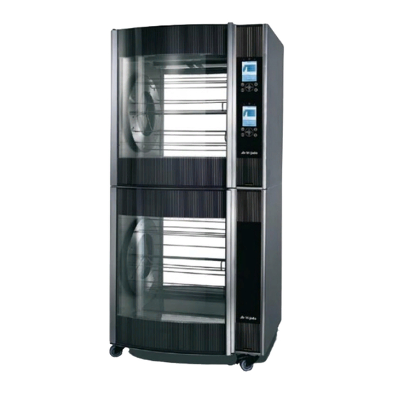
SERVICE MANUAL
STG INTELLIGENT - ROTISSERIE OVEN MODELS
STW INTELLIGENT - WARMER MODELS
MODELS
Single units
Stacked units
WWW.FRIJADO.COM
STG5 intelligent
STG7 intelligent
STG5+STG5 intelligent
STG7+STG7 intelligent
STG5+STW5 intelligent
STG7+STW7 intelligent
This manual is prepared for the use of trained Service Technicians and
should not be used by those not properly qualified. If you have at-
tended a traIning for this product, you may be qualified to perform all
the procedures in this manual.
This manual is not intended to be all encompassing. If you have not
attended a training for this product, you should read, in its entirety,
the repair procedure you wish to perform to determine if you have the
necessary tools, instruments and skills required to perform the proce-
dure. Procedures for which you do not have the necessary tools, instru-
ments and skills should be performed by a trained technician.
Reproduction or other use of this Manual, without the express written
consent of Fri-Jado, is prohibited.
- NOTICE -
Service Manual STG5/7 intelligent STW5/7 intelligent form 9123999 rev. 05/2010
Model
STG7+STG7 intelligent
Advertisement
Table of Contents
Troubleshooting

Subscribe to Our Youtube Channel
Related Manuals for Fri-Jado STG5 intelligent


Summary of Contents for Fri-Jado STG5 intelligent
- Page 1 Procedures for which you do not have the necessary tools, instru- ments and skills should be performed by a trained technician. Reproduction or other use of this Manual, without the express written consent of Fri-Jado, is prohibited. WWW.FRIJADO.COM Service Manual STG5/7 intelligent STW5/7 intelligent form 9123999 rev. 05/2010...
-
Page 2: Table Of Contents
TABLE OF CONTENTS InDEx Index ................................2 General technical data ..........................4 Technical Data Standard Models ......................4 Programming instructions for the STG5/STG7 and STW5/STW7 ............5 Display and keys ............................. 5 Starting the STG ............................. 5 Starting the STW ............................ 6 Add a program ............................ - Page 3 TABLE OF CONTENTS Removal and replacement of parts for the STW5 and STW7 .............. 25 Blower motor ............................25 Thermometer ............................25 Knob ..............................26 Thermostat ............................26 Main switch ............................26 Glass operation panel with backplate ....................27 Heating element ..........................28 Halotherm lamp ...........................
-
Page 4: General Technical Data
GENERAL TECHNICAL DATA GENERal TEChNICal daTa This manual covers the STG series intelligent rotisserie ovens and the STG + STW series intel- ligent combined grills and warmers. Grills are availble in two sizes. Grill and warmer cabinets only come in stacked versions. •... -
Page 5: Programming Instructions For The Stg5/Stg7 And Stw5/Stw7
PROGRAMMING INSTRUCTIONS PROGRAMMInG InSTRUCTIOnS FOR THE STG5/STG7 AnD STW5/STW7 DISPLAy AND kEyS Selection keys (3x) Display Start / Stop key Rotor rotation key OK / Enter key Turning knob On / Off key Cancel key STARTING ThE STG Press and hold the On-Off key for 2 seconds. The display lights up and the oven is On. -
Page 6: Starting The Stw
PROGRAMMING INSTRUCTIONS STARTING ThE STW Turn the thermostat dial to the desired temperature. ADD A PROGRAM Press the program key. Note: when a pin code has been set, first enter the pin code and confirm with OK. Go to add program with turning knob and confirm with OK. - Page 7 PROGRAMMING INSTRUCTIONS Add the program name by use of the up and down keys to change the character and left and right to change the position. Confirm with 2x OK. Select the time row and confirm with OK. Set the time of the cooking step with the turning knob and confirm with OK.
-
Page 8: Start A Program
PROGRAMMING INSTRUCTIONS START A PROGRAM Press the operate key. Select a program with turning knob and confirm with OK. When no preheating is activated, the process starts and is indicated by means of a heating diagram. PRE hEATING When the pre-heating option is activated in the manager menu, the oven will start up with a pre-heat program when starting a program. -
Page 9: Loading Products
PROGRAMMING INSTRUCTIONS LOADING PRODUCTS Press rotor key to start turning the rotor. Press rotor key again to stop. Load the rotisserie with products. Close the door and press the start key. PROGRAM STOP Press the cancel key. Select yes with the turning knob and confirm with OK key. -
Page 10: Optional Functions
PROGRAMMING INSTRUCTIONS OPTIONAL fUNCTIONS • Interrupting an active program • Testing a program • Adding extra time to a program • Alphabetic sorting of programs • Editing a program • Setting a timer • Deleting a program • Demonstration mode INTERRUPTING A PROGRAM Press start/stop key. -
Page 11: Editing A Program
PROGRAMMING INSTRUCTIONS EDITING A PROGRAM Press program key. Note: when a pin code has been set, first enter the code and confirm with OK. Go to “edit program” with the turning knob and confirm with OK. Select the program from the list and confirm with OK If necessary change the name of the program and confirm with OK. -
Page 12: Testing A Program
PROGRAMMING INSTRUCTIONS TESTING A PROGRAM With the test program you can run a pro- gram while it is possible to change time and temperature during the process. Press the program key. Note: when a pin code has been set, first enter the code and confirm with OK. -
Page 13: Setting A Timer
PROGRAMMING INSTRUCTIONS SETTING A TIMER A timer can be programmed to start a program up to 14 days in advance. To be able to use this function the option “auto recipe start” needs to be set to “yes” in the manager menu. -
Page 14: Demonstration Mode
PROGRAMMING INSTRUCTIONS DEMONSTRATION MODE In the demo mode a cooking cycle can be simulated. This function is used for exhibi- tions, the heater will not switch on in this mode. Go to the service menu and use the access code 4878 to gain entry to the menu. Go to “demo mode”... -
Page 15: Switching Off The Unit
PROGRAMMING INSTRUCTIONS SWITChING Off ThE UNIT Press and hold both keys On/Off and Settings until the display light goes out and the oven is turned OFF. Service Manual STG5/7 intelligent STW5/7 intelligent form 9123999 rev. 05/2010 Page 15... -
Page 16: Removal And Replacement Of Parts For The Stg5I And Stg7I
REMOVAL AND REPLACEMENT OF PARTS STG REMOVAL AnD REPLACEMEnT OF PARTS FOR THE STG5I AnD STG7I WARNING: Disconnect the electrical power to the machine at the main circuit box. Place a tag on the circuit box indicating the circuit is being serviced. RIGhT OR LEfT SIDE PANEL Remove the screws that secure the panel to the frame. -
Page 17: Glass Operation Panel With Backplate
Note 1: When reversing the procedure do not forget to apply sealant again over the total height and half way on the bottom side of the panel. The Fri-Jado partnumber for this sealant is 4302375 (Dow Corning 732). Sealant Note 2: Use a stanley knife or any other long... -
Page 18: Cpu Board And Display (Central Processor Unit)
REMOVAL AND REPLACEMENT OF PARTS STG CPU BOARD AND DISPLAy (CENTRAL PROCESSOR UNIT) Before changing the CPU board and display be sure to download or write down the grilling programs. Remove the right side panel according to prior procedure. Disconnect the wiring and flat cables on the board. -
Page 19: Electric Panel
REMOVAL AND REPLACEMENT OF PARTS STG ELECTRIC PANEL 1. Remove the right side panel according prior procedure. 2. Remove the bolt and nuts on the inside bottom of the electric panel. 3. Disconnect the wiring. 4. Lift the electric panel out of the locking slots and remove the panel. -
Page 20: Quartz Lamp
REMOVAL AND REPLACEMENT OF PARTS STG QUARTz LAMP Caution: Do not touch the glass. Moisture from hands could affect the live span of the lamp. The moisture can be removed with alcohol while the lamp is cold. Note: Use a clean rag or paper towel to replace the lamp. -
Page 21: Blower Motor
REMOVAL AND REPLACEMENT OF PARTS STG BLOWER MOTOR Remove the right side panel and the top cover according to prior procedures. Remove the rotor discs, suction and fan plate in the oven. Remove the wing nut on the fan blade and remove fan blade. -
Page 22: Pt1000 Sensor
REMOVAL AND REPLACEMENT OF PARTS STG PT1000 SENSOR Remove the right side panel according to prior procedure. Disconnect the wiring of the sensor. Remove the screw that secures the sensor and remove the sensor. Reverse the procedure to install. Note: The wiring cable is an insulated cable with an earthing screen. -
Page 23: Heating Element
REMOVAL AND REPLACEMENT OF PARTS STG hEATING ELEMENT Remove the rotor discs, right side panel, suction and fan plate according to prior procedures. Disconnect the wiring from the element. Remove the mounting nut. Remove the element from the mounting clip and pull it from the wall. Reverse the procedure to install. -
Page 24: Door Adjustment (Left Side)
REMOVAL AND REPLACEMENT OF PARTS STG DOOR ADjUSTMENT (LEfT SIDE) Remove the left side panel according to prior procedure. Loosen the nuts of the upper hinge. The door must be closed. Loosen the locknut and adjust the bolt in or out to adjust the door. Tighten the nuts of the hinge and mount the left-hand panel. -
Page 25: Removal And Replacement Of Parts For The Stw5 And Stw7
REMOVAL AND REPLACEMENT OF PARTS STW REMOVAL AnD REPLACEMEnT OF PARTS FOR THE STW5 AnD STW7 WARNING: Disconnect the electrical power to the machine at the main circuit box. Place a tag on the circuit box indicating the circuit is being serviced. BLOWER MOTOR Remove the right side panel according to prior procedure. -
Page 26: Knob
REMOVAL AND REPLACEMENT OF PARTS STW kNOB Remove cover plate on the knob with a small screw driver. Loosen the screw inside the knob. Remove the knob with ring. Reverse the procedure to install. Note: check that the back plate is in the right position and runs free from the panel. -
Page 27: Glass Operation Panel With Backplate
Note: When reversing the procedure do not forget to apply sealant again over the total height of the panel and half way on the bottom side. The Fri-Jado partnumber for this sealant is 4302375 (Dow Corning 732). Sealant till half way Service Manual STG5/7 intelligent STW5/7 intelligent form 9123999 rev. -
Page 28: Heating Element
REMOVAL AND REPLACEMENT OF PARTS STW hEATING ELEMENT Remove the right side panel, racks, bot- tom plate and the fan plate according to prior procedures. Disconnect the wiring from the element. Remove the nuts and rings that secure the element and remove the element. Reverse the procedure to install. -
Page 29: Additional Software
ADDITIOnAL SOFTWARE ThE fIPS APPLICATION The FIPS application (Fri-Jado Intelligent Program System) can be used to load and download the cooking programs and to load the system software. The full describtion of the fIPS application can be found in the Service Manual: I-CONTROL SOfTWARE. -
Page 30: Electrical Tests And Service Procedures
ELECTRICAL TESTS AND SERVICE PROCEDURES ELECTRICAL TESTS AnD SERVICE PROCEDURES WARNING: Disconnect the electrical power to the machine at the main circuit box. Place a tag on the circuit box indicating the circuit is being serviced. PT1000 SENSOR TEST Note: When testing the resistance of the sen- Temperature Resistance Ω... -
Page 31: Keypad Test
ELECTRICAL TESTS AND SERVICE PROCEDURES Keypad test To perform a keypad test the unit must be switched off first. Another possibility is to activate this in the “service menu” under “I/O test” and “front panel”. There are 2 keypads. One for the selection keys in the top and one for the function keys below. -
Page 32: Control Location
ELECTRICAL TESTS AND SERVICE PROCEDURES Control loCation Single version Stacked version top rotisserie controls Stacked version bottom rotisserie controls THERMOMETER Controls warm hold cabinet 1 ≈ 25°C 2 ≈ 40°C 3 ≈ 60°C THERMOSTAT DIAL 4 ≈ 80°C 5 ≈ 95°C Page 32 Service Manual STG5/7 intelligent STW5/7 intelligent form 9123999 rev. -
Page 33: General Troubleshooting List
TROUBLESHOOTING GENERal TROublEShOOTING lIST TROUBLEShOOTING ThE STG5/7 ROTISSERIE Symptom Possible causes no power to rotisserie controls. Main breaker open. Fuse burned. Electronic control inoperative. Wiring or flatcable loose. Main fuse or breaker blows. Wiring incorrectly. Heating element, drive motor, blower or magnetic switch shorted. -
Page 34: Troubleshooting The Stw5/7 Warmer
TROUBLESHOOTING TROUBLEShOOTING ThE STW5/7 WARMER Symptom Possible causes no power to warmer controls. Main breaker open. Switch malfunction. Wiring loose. Main fuse or breaker blows. Wiring incorrectly. Heating element or blower shorted. Wiring shorted. Blower motor does not run. Capacitor malfunction. Wiring loose. -
Page 35: Analytic Troubleshooting List
TROUBLESHOOTING aNalyTIC TROublEShOOTING lIST SERVICING AND REPAIRING Of ThE ROTISSERIE STG5/7 This is an analytic description for servicing and repairing all major parts of the rotisseries and warmers. It consists off 4 basic steps to recognize and solve the problems. These steps are: Analyse the symptoms. - Page 36 TROUBLESHOOTING Description of part Symptoms Possible causes Solving: checking/action PT-sensor Temperature indication on no connection Check the wiring. display of 317°C / 603°F between wires. Check thin wire on sensor. Temperature indication on Full contact Check the wiring. display does not go up between wires of sensor.
- Page 37 TROUBLESHOOTING Description of part Symptoms Possible causes Solving: checking/action Display/CPU on operation no illumination on Wiring. Check the wiring. panel and power I/O display Check the power on the board power I/O board by the green LED. Fuse burned. Check the 125 mA fuse on the power I/O board.
- Page 38 TROUBLESHOOTING Description of part Symptoms Possible causes Solving: checking/action Drive motor Motor does not run Wiring. Check the wiring. Check the power to the motor. Coil malfunction. Check resistance of the coils. Between whiteA and white wire 234Ω. Between whiteA and brown wire 117Ω.
-
Page 39: Servicing And Repairing Of The Warmers Stw5/7
TROUBLESHOOTING SERVICING AND REPAIRING Of ThE WARMERS STW5/7 Description of part Symptoms Possible causes Solving: checking/action Outside door Broken glass. Slamming of door. Give instructions to operator. Fastening bolts and nuts Tighten all fastenings. are loose. no sealing ring between Mount new glass with sealing steel and glass. - Page 40 TROUBLESHOOTING Description of part Symptoms Possible causes Solving: checking/action Capacitor Drive motor or blower Wiring. Check the wiring. does not work Capacitor malfunction. Check function after connecting a new capacitor. Checking of the capacitor: Discharge capacitor with a screwdriver. Set meter on MΩ and connect the pins of the meter to the contacts, value goes up.
- Page 41 EXPLODED VIEWS AND PART LISTS Service Manual STG5/7 intelligent STW5/7 intelligent form 9123999 rev. 05/2010 Page 41...
-
Page 42: Exploded Views & Partlists
EXPLODED VIEW AND PARTLISTS ExPLODED VIEWS & PARTLISTS STG 5 I COATED OR STAINLESS STEEL - ShEET METAL WORk STG5i D-0106-01 Page 42 Service Manual STG5/7 intelligent STW5/7 intelligent form 9123999 rev. 05/2010... - Page 43 EXPLODED VIEWS AND PART LISTS Partnum- Item Description 9174060 Cap, top 9146544 Mounting plate, blower 9170428 Side panel, left 9174071 Reinforcement, side plate, left 9170432 Side panel, top 9172220 Bottom plate, coated 9174069 Bottom plate, stainless steel 9174061 Cover, removable 9171012 Sealing profile, silicon 9112430...
-
Page 44: Stg 5 I Coated Or Stainless Steel - Components
EXPLODED VIEW AND PARTLISTS STG 5 I COATED OR STAINLESS STEEL - COMPONENTS Page 44 Service Manual STG5/7 intelligent STW5/7 intelligent form 9123999 rev. 05/2010... - Page 45 EXPLODED VIEWS AND PART LISTS Part- Part- Item Description Item Description number number 51.S 9179859 Door service side, ass. 9179855 Door inside, ass. 9172108 Glass black, outer incl. hinge profile 56-1 9172016 Glass, inner 51-1 9172020 Glass black, outer 56-2 0211520 Bolt M5 x 12 ss hexagon head 51-2...
- Page 46 EXPLODED VIEW AND PARTLISTS Part- Item Description number Operation panel, ass. Glass + backplate 9170073 + keypads 90-1 9172329 Keypads, 15 keys and 3 keys 9172317 CPU board + LCD + cable, ass. 9172314 Flatcable, 14-pol. (i) 9070028 Connecting cable with plug 9192202 Power &...
- Page 47 EXPLODED VIEWS AND PART LISTS Service Manual STG5/7 intelligent STW5/7 intelligent form 9123999 rev. 05/2010 Page 47...
-
Page 48: Stg 7 I Coated Or Stainless Steel - Sheet Metal Work
EXPLODED VIEW AND PARTLISTS STG 7 I COATED OR STAINLESS STEEL - ShEET METAL WORk Page 48 Service Manual STG5/7 intelligent STW5/7 intelligent form 9123999 rev. 05/2010... - Page 49 EXPLODED VIEWS AND PART LISTS Partnum- Item Qty Description 9174099 Cover, removable 9174004 Cap, top 9170640 Cover plate, blower 9170450 Mounting plate, blower 9174016 Ceiling 9170419 Side panel, left 9174013 Reinforcement, side plate, left 9170421 Side panel, top 9172202 Bottom plate, coated 9174010 Bottom plate, stainless steel 9174005...
-
Page 50: Stg 7 I Coated Or Stainless Steel - Components
EXPLODED VIEW AND PARTLISTS STG 7 I COATED OR STAINLESS STEEL - COMPONENTS Page 50 Service Manual STG5/7 intelligent STW5/7 intelligent form 9123999 rev. 05/2010... - Page 51 EXPLODED VIEWS AND PART LISTS Part- Part- Item Description Item Description number number 51.S 9179850 Door service side, ass. 56-5 9174029 Cover profile, inner glass 9172107 Glass black, outer incl. hinge profile 56-6 4285408 nut, M5 51-1 9172019 Glass black, outer 56-7 9174027 Profile...
- Page 52 EXPLODED VIEW AND PARTLISTS Part- Item Description number 9073131 Sealing ring 4289966 Distance ring, outerglass Operation panel, ass. Glass + 9170074 backplate + keypads 90-1 9172329 Keypads, 15 keys and 3 keys 9172317 CPU board +LCD + cable, ass. 9172314 Flat cable, 14 pins 9070028 Connecting cable with plug...
- Page 53 EXPLODED VIEWS AND PART LISTS Service Manual STG5/7 intelligent STW5/7 intelligent form 9123999 rev. 05/2010 Page 53...
-
Page 54: Stw 5 I Sheet Metal Work
EXPLODED VIEW AND PARTLISTS STW 5 I ShEET METAL WORk Page 54 Service Manual STG5/7 intelligent STW5/7 intelligent form 9123999 rev. 05/2010... - Page 55 EXPLODED VIEWS AND PART LISTS Item Part number Qt. Description 9170447 Frame, ass. 9170428 Side panel, left 9174061 Cover, removable 9170432 Side panel, top 9170439 Ventilating plate 9174117 Runner 9174096 Profile for bottom plate 9170480 Side panel, right 9171020 Spacing pin 9170458 Drawer 9174075...
-
Page 56: Stw 5 I Components
EXPLODED VIEW AND PARTLISTS STW 5 I COMPONENTS Page 56 Service Manual STG5/7 intelligent STW5/7 intelligent form 9123999 rev. 05/2010... - Page 57 EXPLODED VIEWS AND PART LISTS Item Part number Qt. Description Item Part number Qt. Description 9170426 Hinge, right 9110048 Blower 9170427 Hinge, left 30-1 9110153 Fanblade 9174115 Under plate 30-2 9073150 Wingnut, left hand threaded 22.S 9179859 Door service side, ass. 9142265 Spray mouth 9172108...
-
Page 58: Stw 7 I Sheet Metal Work
EXPLODED VIEW AND PARTLISTS STW 7 I ShEET METAL WORk Page 58 Service Manual STG5/7 intelligent STW5/7 intelligent form 9123999 rev. 05/2010... - Page 59 EXPLODED VIEWS AND PART LISTS Item Part number Qt. Description 9170449 Frame 9174053 Runner 9170412 Cover plate, blower 9170419 Side panel, left 9174005 Cover, removable 9170421 Side panel, top 9170479 Side panel, right 9174052 Profile for bottom plate 9171020 Spacing pin 9170451 Drawer 9174044...
-
Page 60: Stw 7 I Components
EXPLODED VIEW AND PARTLISTS STW 7 I COMPONENTS Page 60 Service Manual STG5/7 intelligent STW5/7 intelligent form 9123999 rev. 05/2010... - Page 61 EXPLODED VIEWS AND PART LISTS Item Part number Description Item Part number Description 9170426 Hinge, right 9110048 Blower 9170427 Hinge, left 33-1 9110153 Fanblade 9174125 Lamp shade 33-2 9073150 Wingnut, left hand threaded 9052826 Lamp holder 9174139 Spray mouth, blower 9082774 Lamp, Halotherm 200 W 9174115...
-
Page 62: Other Parts
EXPLODED VIEW AND PARTLISTS OThER PARTS fasteners not mentioned in the exploded views Miscellanious items not mentioned in the exploded views Partnum- Partnum- Model Description Model Description All models 0142307 nut M4 SS, DIn 934 All models 0018647 Distance bush All models 0142315 nut M5 SS, DIn 934... -
Page 63: Electrical Diagrams
ELECTRICAL DIAGRAMS ELECTRICAL DIAGRAMS STG 5 I - CIRCUIT DIAGRAM Service Manual STG5/7 intelligent STW5/7 intelligent form 9123999 rev. 05/2010 Page 63... -
Page 64: Stg 5 I - Wiring Diagram
ELECTRICAL DIAGRAMS STG 5 I - WIRING DIAGRAM Page 64 Service Manual STG5/7 intelligent STW5/7 intelligent form 9123999 rev. 05/2010... -
Page 65: Stg 5 I + Stw 5 - Circuit Diagram
ELECTRICAL DIAGRAMS STG 5 I + STW 5 - CIRCUIT DIAGRAM Service Manual STG5/7 intelligent STW5/7 intelligent form 9123999 rev. 05/2010 Page 65... -
Page 66: Stg 5 I + Stw 5 - Wiring Diagram
ELECTRICAL DIAGRAMS STG 5 I + STW 5 - WIRING DIAGRAM Page 66 Service Manual STG5/7 intelligent STW5/7 intelligent form 9123999 rev. 05/2010... -
Page 67: Stg 7 I - Circuit Diagram
ELECTRICAL DIAGRAMS STG 7 I - CIRCUIT DIAGRAM Service Manual STG5/7 intelligent STW5/7 intelligent form 9123999 rev. 05/2010 Page 67... -
Page 68: Stg 7 I - Wiring Diagram
ELECTRICAL DIAGRAMS STG 7 I - WIRING DIAGRAM Page 68 Service Manual STG5/7 intelligent STW5/7 intelligent form 9123999 rev. 05/2010... -
Page 69: Stw 5 I - Circuit Diagram
ELECTRICAL DIAGRAMS STW 5 I - CIRCUIT DIAGRAM Service Manual STG5/7 intelligent STW5/7 intelligent form 9123999 rev. 05/2010 Page 69... -
Page 70: Stw 5 I - Wiring Diagram
ELECTRICAL DIAGRAMS STW 5 I - WIRING DIAGRAM Page 70 Service Manual STG5/7 intelligent STW5/7 intelligent form 9123999 rev. 05/2010... -
Page 71: Stw 7 I - Circuit Diagram
ELECTRICAL DIAGRAMS STW 7 I - CIRCUIT DIAGRAM Service Manual STG5/7 intelligent STW5/7 intelligent form 9123999 rev. 05/2010 Page 71... -
Page 72: Stw 7 I - Wiring Diagram
ELECTRICAL DIAGRAMS STW 7 I - WIRING DIAGRAM Page 72 Service Manual STG5/7 intelligent STW5/7 intelligent form 9123999 rev. 05/2010... - Page 73 Service Manual STG5/7 intelligent STW5/7 intelligent form 9123999 rev. 05/2010 Page 73...
- Page 74 Fri-Jado B.V. • P.O. Box 560 • 4870 AN • Etten-Leur • The Netherlands • tel +31 76 50 85 400 • fax +31 76 50 85 444 • info@frijado.com • www.frijado.com...
Need help?
Do you have a question about the STG5 intelligent and is the answer not in the manual?
Questions and answers