Table of Contents
Advertisement
Quick Links
SERVICE MANUAL
MODELS
TDR 7 p gas
TDR 7+7 p gas
Gas types:
Natural Gas G20/25
Propane G31
(Butane G30)
This manual is prepared for the use of trained Service Technicians and
should not be used by those not properly qualified. If you have attended
a training for this product, you may be qualified to perform all the proce-
dures in this manual.
This manual is not intended to be all encompassing. If you have not at-
tended training for this product, you should read, in its entirety,
the repair procedure you wish to perform to determine if you have the
necessary tools, instruments and skills required to perform the procedure.
Procedures for which you do not have the necessary tools, instruments
and skills should be performed by a trained technician.
Reproduction or other use of this Manual, without the express written
consent of Fri-Jado, is prohibited.
WWW.FRIJADO.COM
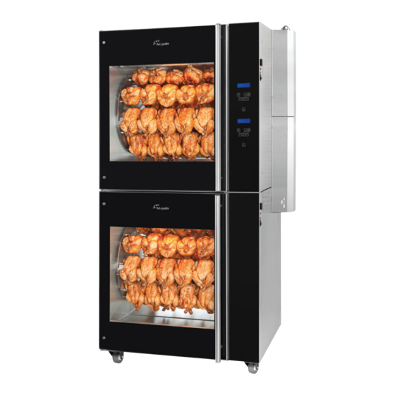
TDR 7 P GAS FIRED
ROTISSERIE OVEN
- NOTICE -
Model TDR 7 P Gas
Service Manual TDR7 P Gas form 9124025 rev. 01/2022
Model TDR 7+7 P Gas
Advertisement
Table of Contents

Related Manuals for Fri-Jado TDR 7 p Gas


Summary of Contents for Fri-Jado TDR 7 p Gas
- Page 1 SERVICE MANUAL TDR 7 P GAS FIRED ROTISSERIE OVEN MODELS TDR 7 p gas TDR 7+7 p gas Gas types: Model TDR 7 P Gas Natural Gas G20/25 Propane G31 (Butane G30) Model TDR 7+7 P Gas - NOTICE - This manual is prepared for the use of trained Service Technicians and should not be used by those not properly qualified.
- Page 2 EMPTY PAGE Page 2 Service Manual TDR7 P Gas form 9124025 rev. 01/2022...
- Page 3 TABLE OF CONTENTS Versions Version Issue date Remarks dd/mm/yy 10/2013 01/10/2013 First release. 01/2014 01/01/2014 Added reset and small textual changes. Exploded views and electric diagrams changed. 03/2014 01/03/2014 Working of rotisserie changed. Error 55 explanation. Small other changes. 11/2014 01/11/2014 New errors, various updates.
-
Page 4: Table Of Contents
TABLE OF CONTENTS INDEX Index ................................4 General technical data ..........................6 Technical data ............................6 Programming instructions TDR p ......................8 Connecting mains power ........................8 Overview of control panel ........................8 Switching on ............................8 Entering the Manager or Service menu ....................9 The USB option read and store (cook books or parameters) ............ - Page 5 Error 55 explanation ..........................43 Exploded views & partlists ........................44 TDR 7 P Gas - electrical parts from serial number 100097688 ............44 TDR 7 P Gas - electrical parts until serial number 100097687 ............46 TDR 7 P Gas - gas parts ........................48 TDR 7 P Gas - doors ..........................
-
Page 6: General Technical Data
GENERAL TECHNICAL DATA This manual covers the TDR 7 P gas fired rotisserie ovens suitable for Natural gas G 20/25 and Propane G 31. • TDR 7 – Oven with 8 spits ( 32 to 40 chickens ) or 7 baskets ( 28 chickens ). - Page 7 GENERAL TECHNICAL DATA Tools • Standard set of tools. • Metric wrenches, sockets and hex socket key wrenches. • Multi-meter. • AC current clamp tester. • Temperature tester. • Insulation value tester (Megger). • Toxicity meter. • Gas pressure meter. •...
-
Page 8: Programming Instructions Tdr P
PROGRAMMING INSTRUCTIONS TDR P CONNECTING MAINS POWER Messages on screen when connecting mains power. Note the bootloader version. Bootloader (Vx.xx.xx) Bootloader (Vx.xx.xx) Bootloader (Vx.xx.xx) No USB stick found Loading application Starting application In progress ...% Bootloader (Vx.xx.xx) Parameters init OK Checking CRC In progress ...% Read language files... -
Page 9: Entering The Manager Or Service Menu
PROGRAMMING INSTRUCTIONS TDR p ENTERING THE MANAGER OR SERVICE MENU Entering the manager menu Entering the service menu Chicken Chicken 98 99 1 3 4 6 6 7 98 99 1 3 4 6 6 7 5 sec. Choose figure Choose figure and confirm (4x) and confirm (4x) - Page 10 PROGRAMMING INSTRUCTIONS TDR p Options in the service menu Option Description Store cook-books and / or parameters to USB. Read cook-books and / or parameters from USB. Function Function test of inputs and outputs, including the keypad Parameters Edit manager parameters. Clock Set time / date and format time / date (12 / 24 clock) Counter...
-
Page 11: The Usb Option Read And Store (Cook Books Or Parameters)
PROGRAMMING INSTRUCTIONS TDR p THE USB OPTION READ AND STORE (COOK BOOKS OR PARAMETERS) Enter the manager or service menu as described before. Also see chapter “Files on USB drive” Manager menu Servicemenu Edit Fu.. Read Store USB read and store USB read and store Read Sto. -
Page 12: Files On The Usb Drive (Strict Rules)
PROGRAMMING INSTRUCTIONS TDR p FILES ON THE USB DRIVE (STRICT RULES) These files can be found on the USB drive regarding the TDRp. The highligted folders and files are fixed and made by the TDRp controller. The other files can be named by yourself, but PAR1.CSV there are strict rules. - Page 13 PROGRAMMING INSTRUCTIONS TDR p Preparing the software (firmware) 3. Connect the mains supply The software comes in a .zip file. The name cor- responds with the version of the software. For example: V1_05_07.zip. 1. Extract the zip file 4. The following messages appear Bootloader version V1.01.02 -USB stick found starting upgrade...
-
Page 14: Manager And Service Parameters
PROGRAMMING INSTRUCTIONS TDR p MANAGER AND SERVICE PARAMETERS Entering the manager parameters Entering the service parameters Chicken Chicken 98 99 1 3 4 6 6 7 98 99 1 3 4 6 6 7 5 sec. Choose figure Choose figure and confirm (4x) and confirm (4x) 4 8 7 8... -
Page 15: Description Of Parameters
PROGRAMMING INSTRUCTIONS TDR p DESCRIPTION OF PARAMETERS In the manager menu, only the green parameters are visible Parameter Description Preheat allowed Enables or disables a preheat step prior to the cooking program (steps) Yes > Preheat is allowed. In the cooking program you can still choose whether or not to preheat. - Page 16 PROGRAMMING INSTRUCTIONS TDR p Parameter Description Lights out Choice of lighting during opening of the door in standby position. The lights will go on for 20 seconds. key beep choice for beep or no beep, with key operation. Temp. offset Temperature offset of PT1000 sensor.
-
Page 17: The Automatic Cook Correction
PROGRAMMING INSTRUCTIONS TDR p THE AUTOMATIC COOK CORRECTION The automatic cook correction facility will automaticly add or deduct time to the pro- grammed cooking time in order to have constant cooking quality. After programming a new program, the first cooking process will be the “learning” process. It is recommended to do the first cook with a half load. -
Page 18: Default Parameters Usa
PROGRAMMING INSTRUCTIONS TDR p DEFAULT PARAMETERS USA Level 1 Level 2 Default Possibilities Information 1.05.2007 software version Manager 1111 Preheat allowed yes - no Preheat temp 50 - 250 Holding allowed yes - no Holding temp 50 - 250 Cook Correction 1 yes - no Eco function 2 yes - no... - Page 19 PROGRAMMING INSTRUCTIONS TDR p EMPTY PAGE EMPTY PAGE Service Manual Turbo Deli Rotisserie form 9120929 rev. 04/2021 Page 19...
-
Page 20: Removal And Replacement Of Parts For The Tdr 7
REMOVAL AND REPLACEMENT OF PARTS REMOVAL AND REPLACEMENT OF PARTS FOR THE TDR 7 WARNING: Disconnect the electrical power to the machine at the main circuit box. Place a tag on the circuit box indicating the circuit is being serviced. RIGHT OR LEFT SIDE PANEL Remove the cross head screws that se- cure the panel to the frame. -
Page 21: Tumble Switch Reset
REMOVAL AND REPLACEMENT OF PARTS TUMBLE SWITCH RESET Remove the right side panel and operating pa- nel according prior procedures. Remove the wiring. Remove the switch by pushing the clamps, on the inside, with a screw driver. Reverse the procedure to install. ELECTRIC PANEL Remove the right side panel and opera- ting panel according prior procedures. -
Page 22: Power And I/O Board
REMOVAL AND REPLACEMENT OF PARTS POWER AND I/O BOARD Remove the right side panel according prior procedure. Disconnect the wiring and flatcable on the board. Remove the board from the clips by pin- ching the clips. Reverse the procedure to install. CPU BOARD Before changing the CPU board and display be sure to download (with a USB stick) or write... -
Page 23: Replacing Of Broken Buzzer
REMOVAL AND REPLACEMENT OF PARTS REPLACING OF BROKEN BUZZER Remove the right side panel according prior procedure. Remove the operating panel according prior procedure. Stick connector of new buzzer in plug next to the existing broken buzzer (see white arrow). Reverse the procedure to install. -
Page 24: Relay
REMOVAL AND REPLACEMENT OF PARTS RELAY Remove the right side panel according prior procedure. Loosen the clamp handle. Gently remove the relay. Reverse the procedure to install. Note: When placing a relay be sure the con- necting pins are in place. DOOR SWITCH Remove the right side panel and the operation panel according prior procedures. -
Page 25: Halogen Lamp Holder (Customer Side)
REMOVAL AND REPLACEMENT OF PARTS HALOGEN LAMP HOLDER (CUSTOMER SIDE) Remove the top cover according prior proce- dure. Remove the wiring of the lamp on the connec- tor. Remove the cap nuts that secure the air suc- tion plate and remove this plate. Remove the glass and lamp from the lamp holder. -
Page 26: Blower Motor
REMOVAL AND REPLACEMENT OF PARTS BLOWER MOTOR 1. Remove the right side panel, the top cover and the air suction plate according prior proce- dures. 2. Remove the wing nut on the fan blade and remove fan blade. (Left handed threads). 3. -
Page 27: Gas Mixture Blower
REMOVAL AND REPLACEMENT OF PARTS GAS MIXTURE BLOWER Remove the right side panel and small top cover plate according prior procedures. Remove the wiring from the top of the gas mix- ture blower Remove the silencer. Remove the 4 nuts from the air inlet (A) and the 4 bolts with nuts from the gas inlet (B) and remove the gas mixture blower. -
Page 28: Gas Control Block
REMOVAL AND REPLACEMENT OF PARTS GAS CONTROL BLOCK Remove the right side panel and the gas burner safety control according prior procedures. Remove the nuts from the pipe clamps to create some clearance. Remove the 4 screws on the top and bottom flange from the gas control block. -
Page 29: Drive Motor
REMOVAL AND REPLACEMENT OF PARTS DRIVE MOTOR Remove the right side panel and rotor discs ac- cording prior procedure. Disconnect the wiring of the motor. Check where the wire, marked A is connected. Remove the screws that secure the fan cover and remove the cover. -
Page 30: Door Glass Inside
REMOVAL AND REPLACEMENT OF PARTS DOOR GLASS INSIDE Separate the inside door from the outside door. 2. Lift the inside door upward out of the hin- ges. Place the new door in the hinges. Close the inside door on the outside door. Note: Tightening of nuts max. -
Page 31: Working Of The Gas Fired Rotisserie
WORKING OF THE GAS FIRED ROTISSERIE WORKING OF THE GAS FIRED ROTISSERIE After plugging the unit in always first check the proper polarity for good ignition. After starting the rotisserie up with the on/off key the reset will light up. First press this switch for 2 seconds till the light is out. -
Page 32: Gas Technical Data
WORKING OF THE GAS FIRED ROTISSERIE GAS TECHNICAL DATA Inlet min pressure (Qn-Hi) Consumption Consumption Specific density type pressure max pressure (Qn-Hi) kg - cfm - LBS m3/h kg/m3 - lb/cf mbar - inch wc - PSI mbar - inch wc - PSI 20 - 8 - 0,3 17 - 7 - 0,25 1,0 - 0,80 - 2.2... -
Page 33: Sticker On Gas Burner Safety Control
WORKING OF THE GAS FIRED ROTISSERIE STICKER ON GAS BURNER SAFETY CONTROL Circuito 24V DC Circuito 115V 24V circuit: 115 V circuit: Tacho (nr.1) = White wire to speed regulation gas HD (nr. 1) = White wire to relay K1. mixture blower. -
Page 34: Electrical Tests And Service Procedures
ELECTRICAL TESTS AND SERVICE PROCEDURES ELECTRICAL TESTS AND SERVICE PROCEDURES WARNING: Disconnect the electrical power to the machine at the main circuit box. Place a tag on the circuit box indicating the circuit is being serviced. PT1000 SENSOR TEST Note: When testing the resistance of the sen- Temperature Resistance Ω... -
Page 35: Control Location
ELECTRICAL TESTS AND SERVICE PROCEDURES CONTROL LOCATION CHICKEN Display 85 1 2 3 7 Undo On / Off List Back Forward Function On / Off Switching the unit On / Off Rotor Undo Go back to previous menu List Recipe / programming modus Forward One step ahead in setting Rotor... -
Page 36: Gas Block Honeywell Type Vk4115V - 2029
ELECTRICAL TESTS AND SERVICE PROCEDURES GAS BLOCK HONEYWELL TYPE VK4115V - 2029 Gas inlet: Inlet of gas after gas pressure reduction valve (max. 22“ H2O). Pressure depending of gas type (see table on page 38). Gas outlet: Outlet of gas into gas mixture blower. Coils: 2 Coils for the gas valves. -
Page 37: Ignition/Ionization Set
ELECTRICAL TESTS AND SERVICE PROCEDURES IGNITION/IONIZATION SET When placing a new ignition/ionization set or for checking the adjustment of this set see dra- wing below. Here you can find the distance between the spark plug and the distance between the ignition pins and the burner bed and the distance between the ionisation pin and the bur- ner bed. -
Page 38: Temporary Bridging Of Reset Switch
ELECTRICAL TESTS AND SERVICE PROCEDURES TEMPORARY BRIDGING OF RESET SWITCH TEMPORARY BRIDGING OF RESET SWITCH For testing of the system, when reset switch could be malfunctioning, it is possible to bridge the For testing of the system, when reset switch could be malfunctioning, it is possible to bridge the reset switch by temporary, for 2 seconds, connecting both the grey and brown wires together. -
Page 39: Flue Gas Analyser
ELECTRICAL TESTS AND SERVICE PROCEDURES FLUE GAS ANALYSER With the flue gas analyser you can measure the exhaust gas on the rotisserie for toxicity. With the use of a Testo 330-1LL you get the following measurements: Testo 330-1LL V1.21 01297080 100035026 G 20 06.03.2014... -
Page 40: Gas Consumption
ELECTRICAL TESTS AND SERVICE PROCEDURES GAS CONSUMPTION With a flow meter you can measure the gas consumption/flow. See table on page 38. To get an accurat consumption you have to do a measurement of 3-5 minutes. During this period the rotisserie the rotisserie may not turn off. MAINTENANCE GAS PROCESSING The customer should have the gas rotisserie periodically checked by a skilled technician accor- ding local, state or national regulations. -
Page 41: Troubleshooting For The Tdr 7 Gas Rotisseries
TROUBLESHOOTING TROUBLESHOOTING FOR THE TDR 7 GAS ROTISSERIES Symptom Possible causes No power to oven controls. 1. Main breaker open. 2. Fuse F1 or F2 burned. 3. Fuse (125 mA) on power and I/O board burned. 4. Wiring loose. Main fuse or breaker blows. 1. - Page 42 TROUBLESHOOTING Symptom Possible causes No ignition of the gas in the burner (reset 1. Reset switch malfunction. light is not burning). 2. Reset light on operation panel broken. 3. Reset on gas control block is on. Press this to reset. See page 44. 4.
-
Page 43: Error 55 Explanation
TROUBLESHOOTING ERROR 55 EXPLANATION Temp. increase °C / 2 minutes minutes Note: 1. Measuring starts 5 minutes after beginning of a heating step. 2. Duration is 5 periods of 2 minutes. 3. Measuring stops at 150°C/302°F or when temp. in cabinet is < 30°C than the set temperature. Necessary line currents: TDR8 with neutral 3x 16A. -
Page 44: Exploded Views & Partlists
EXPLODED VIEWS & PARTLISTS TDR 7 P GAS - ELECTRICAL PARTS FROM SERIAL NUMBER 100097688 J8-J13 Page 44 Service Manual TDR7 P Gas form 9124025 rev. 01/2022... - Page 45 EXPLODED VIEWS AND PARTLISTS Pos. Part number Description Pos. Part number Description Qty. Prio Qty. Prio 9290343 Electric panel, ass. 9171136 Glass lamp holder 9292040s CPU board + LCD 9140027 Blower + fanblade + wing- 9292041 Keypad + short flatcable 9293002s Gear motor, complete with 9192400s...
-
Page 46: Tdr 7 P Gas - Electrical Parts Until Serial Number 100097687
EXPLODED VIEWS AND PARTLISTS TDR 7 P GAS - ELECTRICAL PARTS UNTIL SERIAL NUMBER 100097687 Page 46 Service Manual TDR7 P Gas form 9124025 rev. 01/2022... - Page 47 EXPLODED VIEWS AND PARTLISTS Pos. Part number Description Pos. Part number Description Qty. Prio Qty. Prio 9171136 Glass lamp holder 9292040S CPU board + LCD 9140027 Blower + fanblade + wing- 9292041 Keypad + short flatcable 9293002s Gear motor, complete with drive head 9172314 Ribbon cable L= 1500 mm,...
-
Page 48: Tdr 7 P Gas - Gas Parts
EXPLODED VIEWS AND PARTLISTS TDR 7 P GAS - GAS PARTS updated 2021 TDR8P Gas USA Page 48 Service Manual TDR7 P Gas form 9124025 rev. 01/2022... - Page 49 EXPLODED VIEWS AND PARTLISTS Pos. Part number Description Qty. Prio 9290550 Heat exchanger 9292106 Insulation, heat exchanger 9292109 Insulation board, heat exchanger 9290221 Insulation + sheet left ass. 9290222 Insulation + sheet right ass. 9070793 3d nut M6 9292107 Insulation exhaust pipe 9291018 Spring for insulation exhaust pipe 9291030...
-
Page 50: Tdr 7 P Gas - Doors
EXPLODED VIEWS AND PARTLISTS TDR 7 P GAS - DOORS Page 50 Service Manual TDR7 P Gas form 9124025 rev. 01/2022... - Page 51 EXPLODED VIEWS AND PARTLISTS Pos. Part number Description Qty. Prio 205 9298510s Door service side, ass., TDR7/8m 206 9298513s Door customer side, ass., TDR7/8m 207 9298512s Door inside, ass., TDR7/8m 215 9290410 Hinge, right 216 9290409 Hinge, left 217 9172054 Brass bearing 8 mm 218 9172122 Brass bearing 8 mm, adjusted...
-
Page 52: Tdr 7 P Gas - Rotor
EXPLODED VIEWS AND PARTLISTS TDR 7 P GAS - ROTOR 9292295 Untill serial number 100075953 Page 52 Service Manual TDR7 P Gas form 9124025 rev. 01/2022... - Page 53 EXPLODED VIEWS AND PARTLISTS Pos. Part number Description Qty. Prio 3701228 Capacitor 2.5 uF 9293002s Gear motor, complete with drive head 2000072 Fanblade Ø 150 mm, gearmotor 9073131 Seal ring, Teflon 9110797 Seal, silicon 9290444 Support plate, rotor motor 9172274 Rotorset ass.
-
Page 54: Tdr 7 P Gas - Stacking Parts
EXPLODED VIEWS AND PARTLISTS TDR 7 P GAS - STACKING PARTS Page 54 Service Manual TDR7 P Gas form 9124025 rev. 01/2022... - Page 55 EXPLODED VIEWS AND PARTLISTS Pos. Part number Description Qty. Prio 9292107 Insulation exhaust pipe 9291018 Spring for insulation exhaust pipe 9292120 Coupler tube + coupling 1/2" OD 9290551 Gas tube 1/2” with suspension 9171053 Elbow 1/2" 9173072 Tube 1/2" NPT 130mm 9292232 Exhaust elbow 9291106...
-
Page 56: Tdr 7 P Gas - Sheet Metal
EXPLODED VIEWS AND PARTLISTS TDR 7 P GAS - SHEET METAL Page 56 Service Manual TDR7 P Gas form 9124025 rev. 01/2022... - Page 57 EXPLODED VIEWS AND PARTLISTS Pos. Part number Description Qty. Prio ..Frame, ass. 9171125 Leg, rubber 50 mm 9294180 Side panel, left 9294018 Side panel, right 9294160 Top cover 9294032 Top plate 9294422 Cover, removeable 9174485 Cover, exhaust 9174408 Plate, air guide 9170568 Mounting plate, blowers 9290528...
-
Page 58: Tdr 7 P Gas - Insulation
EXPLODED VIEWS AND PARTLISTS TDR 7 P GAS - INSULATION Page 58 Service Manual TDR7 P Gas form 9124025 rev. 01/2022... - Page 59 EXPLODED VIEWS AND PARTLISTS Pos. Part number Description Qty. Prio 9292118 Insulation top, large 9292119 Insulation top, small 9293089 Insulation 141x21-28 9293090 Insulation 623x180 9293087 Insulation 327x730 9293085 Insulation 110x735 9293086 Insulation 210x730 9293088 Insulation 110x670 Service Manual TDR7 P Gas form 9124025 rev. 01/2022 Page 59...
-
Page 60: Fasteners
EXPLODED VIEWS AND PARTLISTS FASTENERS Pos. Part number Description Pos. Part number Description 800 4280107 Bolt M6x20 ZP 854 0141076 Screw M3x20, SS Cross recess pan head 801 4289559 Lockwasher M6, serrated ZP 855 0141078 Screw M3x30, SS Cross recess pan 802 4288321 Screw M5x16, SS socket button head. - Page 61 EXPLODED VIEWS AND PARTLISTS Pos. Part number Description Pos. Part number Description 902 4288319 Screw 6x20, ZP CR threadforming 954 4285084 Screw 4,8x19, ZP Self drilling and tapping. 903 4289402 Lockwasher M8, ZP 955 9008217 Blind rivet 4x8,6 904 3701280 Lockwasher, starlock for 10mm shaft 956 9174680 Washer ø5,2xØ20x2mm...
-
Page 62: Electrical Diagrams
ELECTRICAL DIAGRAMS CIRCUIT DIAGRAM TDR 7 P GAS FROM SERIAL NUMBER 100097688 M4-PWR(115V) M4-1 M4-2 M4-5 M4-4 Ionisation Pin Ignition HIGH LIMIT BLOWERS TRAFO 230/12V R1 PT1000 OVEN TEMP. GAS BLOWER DOOR SWITCHES ROTOR CONTROLLED BY TOP UNIT LOCATED IN BOTTOM UNIT... -
Page 63: Wiring Diagram Tdr 7 P Gas From Serial Number 100097993
ELECTRICAL DIAGRAMS WIRING DIAGRAM TDR 7 P GAS FROM SERIAL NUMBER 100097688 Operator Side Customer Side HIGH LIMIT THERMOSTAAT 320 °C TB1/OR TB1/YE J8-2 93 12 BLOWER RG128 J8-1 RESET ~115V CONTROL ~230V J9-2 TB1/GN BU WH BK GY J9-1... -
Page 64: Circuit Diagram Tdr 7 P Gas Untill Serial Number 100097992
ELECTRICAL DIAGRAMS CIRCUIT DIAGRAM TDR 7 P GAS UNTILL SERIAL NUMBER 100097687 M4-PWR(115V) M4-1 M4-2 M4-5 M4-4 Ionisation Pin Ignition HIGH LIMIT CONTROLLED BY TOP UNIT LOCATED IN BOTTOM UNIT FAN (OPTION) BLOWERS GAS BURNER CONTROL TRAFO 230/12V ROTOR GAS BLOWER... -
Page 65: Wiring Diagram Tdr 8 P Gas Untill Serial Number 100097992
ELECTRICAL DIAGRAMS WIRING DIAGRAM TDR 8 P GAS UNTILL SERIAL NUMBER 100097687 X3-13/GY X3-5/BK K1-21 X3-1/WH M4-PWR(115V) X3-9/BU CB3-12 CB3-14 X1-3/GY X1-2/BN X1-7/YE M4-1 M4-2 X3-13/GY X3-5/BK X3-1/WH M4-5 M4-4 X3-9/BU ionisation X1-3/GY GREY BLUE YELLOW WHITE WHITE (24) 230V ONLY X1/OR T2/BK (25) 230V ONLY... -
Page 66: Circuit Diagram Tdr 7 P Gas Untill Serial Number 100080362
ELECTRICAL DIAGRAMS CIRCUIT DIAGRAM TDR 7 P GAS UNTILL SERIAL NUMBER 100080362 Page 66 Service Manual TDR7 P Gas form 9124025 rev. 01/2022... -
Page 67: Wiring Diagram Tdr 7 P Gas Untill Serial Number 100080362
ELECTRICAL DIAGRAMS WIRING DIAGRAM TDR 7 P GAS UNTILL SERIAL NUMBER 100080362 Service Manual TDR7 P Gas form 9124025 rev. 01/2022 Page 67... - Page 68 EMPTY PAGE Page 68 Service Manual TDR7 P Gas form 9124025 rev. 01/2022...
- Page 69 For parts call: 877 392-7851 Fri-Jado Inc. •1401 Davey Road • Sweet 100 • Woodridge, IL. 60517 • USA • tel. 630-630-7950 • fax 630-689-11424 • toll free 877-FRI-JADO • us.info@frijado.com • www.frijado.com Page 69 Service Manual TDR7 P Gas form 9124025 rev. 01/2022...
Need help?
Do you have a question about the TDR 7 p Gas and is the answer not in the manual?
Questions and answers