Table of Contents
Advertisement
Quick Links
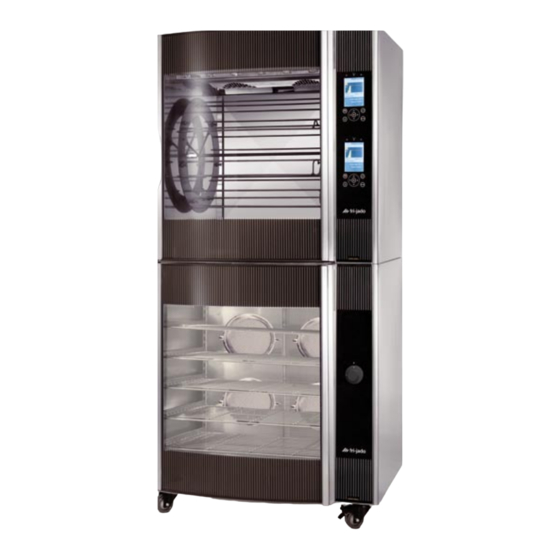
SERVICE MANUAL
SINGLE UNITS:
STO6-i UK
STO6-i EURO
This manual is prepared for the use of trained Service Technicians and should
This manual is not intended to be all encompassing. If you have not attended a
ments and skills required to perform the procedure. Procedures for which you
Reproduction or other use of this Manual, without the express written consent of
WWW.FRIJADO.COM
STO6-INTELLIGENT
STACKED UNITS:
STO6-i+STG8-i TURBO
STO6-i+STG7-i TURBO
STO6-i+STO6-i
not be used by those not properly qualified. If you have attended a training
for this product, you may be qualified to perform all the procedures in this
training for this product, you should read, in its entirety, the repair procedure
you wish to perform to determine if you have the necessary tools, instru-
do not have the necessary tools, instruments and skills should be performed
- NOTICE -
manual.
by a trained technician.
Fri-Jado, is prohibited.
Service Manual STO6-i form 9123720 rev. 12/2008
Advertisement
Table of Contents

Subscribe to Our Youtube Channel
Related Manuals for Fri-Jado STO6-INTELLIGENT


Summary of Contents for Fri-Jado STO6-INTELLIGENT
- Page 1 Reproduction or other use of this Manual, without the express written consent of Fri-Jado, is prohibited. WWW.FRIJADO.COM Service Manual STO6-i form 9123720 rev. 12/2008...
- Page 2 TABLE OF CONTENTS EMPTY PAGE Service Manual STO6-i form.9123720 rev. 12/2008 Page 2...
-
Page 3: Table Of Contents
TABLE OF CONTENTS INdEx Index ............................3 General technical data ....................... 5 Programming instructions for the STO6-I ................. 6 Mains supply ....................................6 Display and keys ..................................6 General information .................................. 7 Starting the unit ..................................7 Switching off the unit ................................7 Programming functions ................................ - Page 4 TABLE OF CONTENTS Exploded views & partlists ....................... 26 Electrical diagrams ........................32 Appendix ............................ 1 Replacement of shaft sealing for blower moter ovens ......................2 Service Manual STO6-i form.9123720 rev. 12/2008 Page 4...
-
Page 5: General Technical Data
GENERAL TECHNICAL DATA GENERal TEChNICal daTa This manual covers the STO 6-i series ovens. They are based on a STG SB (Solid Back) housing and can only be stacked with SB housings such as another STO 6-i , a STG 8-i Turbo and STG 7-i Turbo •... -
Page 6: Programming Instructions For The Sto6-I
PROGRAMMING INSTRUCTIONS PROGRaMMING INSTRuCTIONS FOR ThE STO6-I MAINS SUPPLY If there is a main switch present ,turn it to “1”. Power will be supllied to the STO now. DISPLAY AND KEYS Selection keys (3x) Display Start/Pause key Door open(not used) OK/Enter key Turning knob Stop/Cancel key... -
Page 7: General Information
PROGRAMMING INSTRUCTIONS GENERAL INfORMATION The steps described in this chapter are a summary of the steps described in form 9123687 - Service Manual I-control. Please refer to this manual for further information about the function you want to perform. STARTING ThE UNIT Press and hold the On-Off key for 2 seconds. -
Page 8: Programming Functions
PROGRAMMING INSTRUCTIONS PROGRAMMING fUNCTIONS Overview of program functions Overview of keyboard functions - Turning knob: in menu: Selecting function Adding a program in field: changing value Editing a program - Arrows: selecting function or field Deleting a program in field: changing value Testing a program - OK : Confirming your choice. -
Page 9: Program Start
PROGRAMMING INSTRUCTIONS PROGRAM START Press the operate key. Select a program with the turning knob and confirm with OK. When no preheating is activated, the process starts and is indicated by means of a heating diagram. STOP A PROGRAM Press the cancel key. Confirm the cancellation by selecting YES and pressing the OK key. -
Page 10: Introduction
PARAMETER LISTINGS PaRaMETER lISTING STO6-I INTRODUCTION This chapter describes how to reach the parameters in the unit and where to find more information about them. Please refer to form 9123687 - Service Manual I-control for more detailed infor- mation about the function you want to perform or the parameter value(s) you want to check or change. -
Page 11: Adapting Parameters
Service parameters: (see I-control manual.) The parameters marked in grey are considered critical and should not be changed. If a para- meter needs to be adjusted , the Fri-jado Service Department will contact you with a request to make the adjustment. -
Page 12: Removal And Replacement Of Parts
REMOVAL AND REPLACEMENT OF PARTS REMOVal aNd REPlaCEMENT OF PaRTS wARNING: Disconnect the electrical power to the machine at the main circuit box or pull the plug. Place a tag on the circuit box indicating the circuit is being serviced. RIGhT OR LEfT SIDE PANEL 1. -
Page 13: Removal Of The Tray Supports Right And Left Side
REMOVAL AND REPLACEMENT OF PARTS REMOVAL Of ThE TRAY SUPPORTS RIGhT AND LEfT SIDE Remove the trays or racks Remove the tray supports by lifting them out of their support pins and pulling them to the centre of the cabinet. Remove the tray support out of the cabi- net. -
Page 14: Fuse
REMOVAL AND REPLACEMENT OF PARTS fUSE Remove the right side panel according prior procedure. The fuse is situated just above the contac- tor on the electrical panel (see arrow and exploded view of electr. assembly) Push the fuseholder open with a screwdri- ver and measure the fuse. -
Page 15: Power / I/O Board And Fan Control Board
REMOVAL AND REPLACEMENT OF PARTS POwER / I/O BOARD AND fAN CONTROL BOARD Remove the right side panel according prior procedure. Disconnect wiring and flat cable on the board you want to remove. Number or mark the wiring if necessary. Remove the board from the clips by pres- sing the clips together. -
Page 16: Contactor
REMOVAL AND REPLACEMENT OF PARTS CONTACTOR Remove the right side panel according prior procedure. Disconnect the wires to the contactor. Push down the locking tab and remove the contactor from the mounting bracket. Reverse the procedure to install. PT1000 SENSOR Remove the right side panel according to prior procedure. -
Page 17: Glass Panel With Back Plate
REMOVAL AND REPLACEMENT OF PARTS 6. Remove the element out of the cabinet- from the front side. 7. Reverse the procedure to install. Note 1: when disconnecting or connecting the wiring, secure the element by holding the rear nut with an open-ended spanner. GLASS PANEL wITh BACK PLATE Remove the right side panel according prior procedure. -
Page 18: Cooling Fan
REMOVAL AND REPLACEMENT OF PARTS COOLING fAN Remove the right panel side according prior procedure. Loosen the screws from the small top co- ver at the rearside for about 10 mm. Disconnect the wiring from the power board. Remove the small rear panel by loosening the 2 M5 nuts and lifting the rear panel out of the slotted holes. -
Page 19: Blower Motor
REMOVAL AND REPLACEMENT OF PARTS BLOwER MOTOR Remove the right panel side according prior procedure. Remove the rear panel according prior procedure. Remove the filter assembly according prior procedure. Remove the fan blades of the 2 blowers, that are on the same vertical subframe. Disconnect the 2 blowers from the fan- board. -
Page 20: Main Switch
REMOVAL AND REPLACEMENT OF PARTS MAIN SwITCh DISCONNECT ThE MAINS SUPPLY !!! Remove the right panel side according prior procedure. Disconnect the wiring from the switch, if they are not numbered, please do so before disconnecting them. Remove the cap and the knob at the front Loosen both screws and the switch will come off. -
Page 21: Door Glass Inside
REMOVAL AND REPLACEMENT OF PARTS DOOR GLASS INSIDE Lift the door upward out of the hinges and place on a table. Remove the cap nuts and washers on the profiles of the door. Remove the profiles from the glass. Mount the profiles on the new glass. Do not forget the PFTE washers inside the holes and the washers between metal and glass. -
Page 22: Electrical Tests And Service Procedures
ELECTRICAL TESTS AND SERVICE PROCEDURES ElECTRICal TESTS aNd SERVICE PROCEduRES wARNING: Disconnect the electrical power to the machine at the main circuit box or pull the plug during the mechanical checks. Place a tag on the circuit box indicating the circuit is being serviced. PT 1000 SENSOR •... -
Page 23: Door Switch
ELECTRICAL TESTS AND SERVICE PROCEDURES DOOR SwITCh • Remove the right side panel (see removal and replacement). • Remove both wires from the switch. • Place an ohmmeter over the contacts. • Measure the resistance. Resistance should be at least several KOhms with the door open, if not then the contact inside sticks and the switch should be replaced. -
Page 24: Troubleshooting For The Sto6-I
TROUBLESHOOTING TROublEShOOTING FOR ThE STO6-I Listed below is a table with symptoms and a list of possible causes and solutions to these problems. The list contains the most common occurences and solutions. TROUBLE ShOOTING LIST Symptom Possible Cause Possible solution No power to unit. - Page 25 TROUBLESHOOTING Symptom Possible Cause Possible solution halogen lamp(s) do not light up lamp(s) broken Replace the lamp(s) Wiring loose Check wiring Transformer malfunction Secundary voltage should be around 12 Vac Parameter setting not correct Correct this setting in the manager menu No display and /or keypads does not function no supply voltage, check if green leds on the controlboard are on.
-
Page 26: Exploded Views & Partlists
EXPLODED VIEWS AND PARTLISTS ExPlOdEd VIEWS & PaRTlISTS STO6-i - Sheet Iron Work Service Manual STO6-i form.9123720 rev. 12/2008 Page 26... - Page 27 EXPLODED VIEWS AND PARTLISTS 38-4 38-6 38-7 38-5 38-8 38-7 38-1 38-5 38-8 38-4 38-6 38-1 38-3 38-12 38-2 38-4 38-4 38-9 39-4 39-10 38-10 39-7 39-8 38-11 39-9 34-1 39-3 39-6 42-1 42-2 39-11 42-3 39-1 39-5 39-12 39-2 (34-1) See exploded 71-2...
- Page 28 EXPLODED VIEWS AND PARTLISTS 98-1 98-2 98-3 108-1 108-2 108-3 108-4 108-5 STO6-i - Fan assembly Service Manual STO6-i form.9123720 rev. 12/2008 Page 28...
- Page 29 EXPLODED VIEWS AND PARTLISTS 34-1 34-2 34-3 34-4 34-5 34-10 34-6 34-9 34-8 34-11 34-7 STO6-i - Electrical asssembly Service Manual STO6-i. form.9123720 rev. 12/2008 Page 29...
- Page 30 EXPLODED VIEWS AND PARTLISTS Item Partnr. Description Item Partnr. Description 9170614 Inner frame 39-7 4289966 distance ring, outerglass 9170419 Side panel, left 39-8 4311110 Washer 9175174 Plate, upper, right 39-9 4285408 Nut, M5 9170479 Side panel, right 39-10 9174023 Mounting profile, hinge side STG7 3701233 door switch 39-11...
- Page 31 EXPLODED VIEWS AND PARTLISTS Item Partnr. Description 3702021 heating element, 1750 W 9172355 heating element, 1800 W 9044564 Connecting block, 1,2,3 9044572 Connecting block, 4,5,6 3702324 Gasket,heating element 1800W 3702364 Gasket, heating element 1750W 3500325 Service set shaft sealing 108-1 3500577 O-ring 16x2 mm 108-2...
-
Page 32: Electrical Diagrams
ELECTRICAL DIAGRAMS ElECTRICal dIaGRaMS STO6-i - Circuit diagram uK Service Manual STO6-i form. 9123720 rev. 12/2008 Page 32... - Page 33 ELECTRICAL DIAGRAMS STO6-i - Wiring diagram uK Service Manual STO6-i form.9123720 rev. 12/2008 Page 33...
- Page 34 ELECTRICAL DIAGRAMS STO6-i -Circuit diagram EuRO Service Manual STO6-i form. 9123720 rev. 12/2008 Page 34...
- Page 35 ELECTRICAL DIAGRAMS STO6-i - Wiring diagram EuRO Service Manual STO6-i form.9123720 rev. 12/2008 Page 35...
- Page 36 EMPTY PAGE Service Manual STO6-i form.9123720 rev. 12/2008 Page 40...
- Page 37 Fri-Jado B.V. • P.O. Box 560 • 4870 AN • Etten-Leur • The Netherlands • tel +31 76 50 85 400 • fax +31 76 50 85 444 • info@frijado.com • www.frijado.com...
-
Page 38: Appendix
aPPENdIx Replacement shaft sealing rev 08/2008 Page 1... -
Page 39: Replacement Of Shaft Sealing For Blower Moter Ovens
REPLACEMENT Of ShAfT SEALING fOR BLOwER MOTER OVENS After replacing the blower motor, a new shaft sealing set has to be mounted. Photo’s 2 until 10 show how to prepare the fan blade before mounting it on the shaft. Photo’s 11 until 14 show the actual mounting of the fan blade. - Page 40 Make sure that the outside of the tool you use is not wider than the locking ring, other- wise you might damage the locking pin for the seal ring!!!! This is how it should look like . Put the spring over the hollow shaft. Place the O-ring in the PFTE sealing ring.
- Page 41 Place the PFTE sealing ring over the hollow shaft until it rests on the spring. The hole in the sealing ring must be opposite the pin of the drive ring. Push and hold the PFTE sealing ring over the hollow shaft and secure it with an elastic cord.
- Page 42 Remove the elastic cord and turn the fan blade to check if it is running smooth. Tighten the screw and check again. Replacement shaft sealing rev 08/2008 Page 5...
- Page 43 EMPTY PAGE Page 6 Replacement shaft sealing rev. 08/2008...
Need help?
Do you have a question about the STO6-INTELLIGENT and is the answer not in the manual?
Questions and answers