Table of Contents
Advertisement
Quick Links
Advertisement
Table of Contents

Related Manuals for Atlas PSP-6000


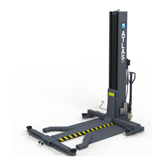
Summary of Contents for Atlas PSP-6000
- Page 2 Important Information Introduction Thoroughly read this manual before operating the lift and comply with the instructions. Always display the manual in a conspicuous location. Personal injury and property damage incurred due to non-compliance with these safety instructions are not covered by the product liability regulations. Intended Use Th is single column vehicle lift is classifi...
-
Page 3: Safety Instructions For Servicing
• Make sure the vehicle doors are closed during raising and lowering cycles. • Closely watch the vehicle and the lift during raising and lowering cycles. • Do not allow anyone to stay in lift area during raising and lowering cycles. •... -
Page 4: Machin E Demolition
Equalizing System The lift is equipped with dis tributing and connecting fl ow valve to ensure level movement of carriage. Pipe Break Valve The hydraulic cylinders are equipped with pipe break valves. They respond in case of rapid pressure drop (line break) to prevent sudden lowering movements. Pressure Relief Valve A pressure relief valve is used to limit the hydraulic working pressure to a maximum of 200bar. -
Page 5: Specifications
Specifi cations Lifting Max. Lifting Overall Dimension Noise Weight Voltage Capacity Height Maximum (L*W*H) 111 1/2” x 1,900 110V, 6,000lbs 71 2/3” <70 dB 96” x 102 3/4” 1-phase... -
Page 7: Lifting And Handling
Transport/Packing/Storage Only skilled personnel who are familiar with the lift and this manual shall be allowed to carry out packing, lifting, handling, transport and unpacking operations. Packing 90% components were pre-assembled before shipment, and packed with blister packing in steel frame. Arms, adapters and rubber pads were put in the lift. Power unit was packed in carton box separately, power unit stand was packed and fi... -
Page 8: Installation Requirements
Installation Requirements Working Site The user should prepare the working site for the lift before its arrival. The lift must be placed on fl at and hard ground, which is made of cement or bricks, with the load at the position of vertical post of 3t/m2. There should be > about 40” space around the lifted vehicle, and the net height indoor should be about 12’. -
Page 9: Installation Procedure
Installation Procedure After unloading the lift, place it near the intended installation location. Remove the shipping bands and lay out the pieces to take inventory. - Page 10 Remove packing materials.
- Page 11 Hoist the column onto the frame base, lining up the bolt holes. Optional Turnbuckle Shown...
- Page 12 Secure the column with the hex head bolts and washers. Raise the carriage by hand. Ready the hex head bolts.
- Page 13 Hoist the lifting frame, lining up the bolt holes with the column’s carriage.
- Page 14 Secure the lifting frame with the hex head bolts and washers. Slide the off-side arm assembly into the lifting frame and tighten the screw on top of the lifting frame to secure it.
- Page 15 10. Slide the column-side arms into the lifting frame and tighten the screw on top of the lifting frame to secure it. 11. Screw the adapter holder onto the column.
- Page 16 12. Unwrap the ball bearing on the wheel assembly. 13. Secure the wheel assembly to the column with the axis pin and tighten set screw along with jam nut.
- Page 17 14. Install the power unit onto the column with washers and hexagon screws. Note: Quick connect fi tting on the power unit reservoir is not used.
- Page 18 15. Remove existing pipe fi tting from hydraulic cylinder 16. Prepare new pipe fi tting with O-ring washer and Thread Seal Tape...
- Page 19 17. Install new pipe fi tting into hydraulic cylinder 18. Connect and tighten the oil hose to the power unit and hydraulic fi tting...
-
Page 20: Operation Flow
Operation Instructions Operation Rules For Mechanism System The movable single column lift is provided with separate traveling mechanism. Pump the hauling handle of the steering rear wheel forwards and backwards to make the vertical column off the ground, then you can push or pull the lift. On arriving the working site, press the valve handle to retract the wheel, then the vertical column lands on the ground steadily. - Page 21 11. To adjust lifting pad, turn it anticlockwise to make it rise ( adjustment distance of 4”) 12. Press the “” button again and pay attention to lifting arm and the vehicle lifted until lifting is safe and reliable. 13. Raise the lift to the required height, then lower it to the lock position 14.
- Page 22 Movable lift pushed into the underside of the vehicle Vehicle driving onto the lift...
- Page 23 Use lifting arm Movable Lift According to the position under the vehicle chassis where the lifting arm is located, the supporting arm on the lifting arm (close to the vertical post) may be pushed and pulled up and down or to left and right, as the following fi...
-
Page 24: Maintenance
Maintenance For daily maintenance and service of the lift, see operation steps, use, and cautions described in the previous pages. The working environment and the surface of this machine should be cleaned usually. During the use of this machine, if any oil leaking is found, check the leakage source. -
Page 25: Troubleshooting
Troubleshooting PROBLEM SOLUTION Motor Does Failure of the motor to operate is normally caused by Not Operate one of the following: Breaker or fuse blown. Faulty wiring connections; call electrician. Defective up button; call electrician for service. Motor If the motor is functioning, but the lift will not rise do Functions but the following in the order given: Lift Will Not... - Page 26 Oil Blows out If oil blows out of the breather of the power unit, take Breather of the following actions: Power Unit Oil reservoir overfi lled. Relieve all pressure and siphon out hydraulic fl uid until at a proper level Lift lowered too quickly while under a heavy load.
-
Page 27: Parts Lists
Parts Lists... - Page 28 Name Note Under Frame Stand Column Outer Hexagon Screw M16*45 Washer Ф16 Washer Ф12 Outer Hexagon Screw M12*30 Wheel Bearing 62042Rs Shaft For Front Wheel Washer Ф20 Snap Pin 3*35 Lifting Frame Back Telescopic Boom(Horizontal) Back Telescopic Boom Longer Arm Rack Spring Ф18*2*70...
- Page 29 Name Note Upper Fixed Seat Fixed Pin Lower Fixed Seat Inner Hexagon Screw M8*25 Handle Washer Ф8 Wheel Ф160*50 Jump Ring Ф20 Joining Beam Axis Pin Hydraulic Power Supply Oil Pipe Connection High-Pressure Oil Pipe Elevating Scaffold Sliding Block Tension Spring Ф13*1.2*60 Unlocking Handle Axis Pin...
-
Page 30: Circuit Diagram
Circuit Diagram EK: Main switch FU: Fuse KM: Contactor M: Motor JBK: Transformer HL: Lamp SB: UP button SA: Top limit switch... - Page 31 Hydraulic Diagram 1. Cylinder 2. Filter 3. Oil pump 4. Motor 5. One-way valve 6. Manual release valve 7. Throttle valve 8. Relief valve 9. Anti-leakage valve Learn more about automotive tools on our website.
Need help?
Do you have a question about the PSP-6000 and is the answer not in the manual?
Questions and answers