Table of Contents
Advertisement
Quick Links
Advertisement
Table of Contents

Related Manuals for Atlas Kwik Bay


Summary of Contents for Atlas Kwik Bay
- Page 1 Replace This With Cover PDF...
- Page 2 Revised 2/20/2019 Read this entire manual before operation begins. Record below the following information which is located on the serial number data plate. Serial No. Model No. Date of Installation...
-
Page 3: Table Of Contents
Contents General Information..5 Product Identifi cation ..8 Packing/Transport/Storage..10 Product Description ..12 Technical Specifi... - Page 4 Indicates the direction of access for motor vehicles to the lift BOLD Important information TYPE WARNING: Before operating the lift and carrying out any adjustments, read Chapter 7 “Installation” carefully. All proper operations for a better functioning lift are shown. Kwik Bay...
-
Page 5: General Information
• Any use of the machine made by operators who are not familiar with the instructions and procedures contained herein shall be forbidden. This manual is an integral part of the lift: it shall be given to the new owner if and when the lift is resold. General Information Kwik Bay... - Page 6 The manufacturer has paid proper attention to the preparation of this manual. However, nothing contained herein modifi es or alters, in any way, the terms and conditions of manufacturer agreement by which this lift was acquired, nor increase, in any way, manufacturer’s liability to the customer. General Information Kwik Bay...
- Page 7 The manufacturer is not liable for any mistakes made when drawing up this manual and reserves the right to make any changes due the development of the product, at any time. General Information Kwik Bay...
-
Page 8: Product Identifi Cation
Wear items are covered by a 90 day warranty. The warranty will come immediately to an end when unauthorized modifi cations to the machine or parts of it are carried out. The presence of defects in workmanship must be verifi ed by the Manufacturer’s personnel in charge. Product Identification Kwik Bay... - Page 9 Dealer where the machine was bought, or the Manufacturer’s Commercial Department. Only skilled personnel who are familiar with the lift and this manual shall be allowed to carry out packing, lifting, handling, transport and unpacking operations. Product Identification Kwik Bay...
-
Page 10: Packing/Transport/Storage
Packages must be stored in a covered place, out of direct sunlight and in low humidity, at a temperature between 14°F and 104°F. Stacking is not recommended: the package’s narrow base, as well as its considerable weight and size make it diffi cult and hazardous. Packing/Transport/Storage Kwik Bay... - Page 11 Packages must be opened paying attention not to cause damage to people (keep a safe distance when opening straps) and parts of the lift (be careful the objects do not drop from the package when opening). Packing/Transport/Storage Kwik Bay...
-
Page 12: Product Description
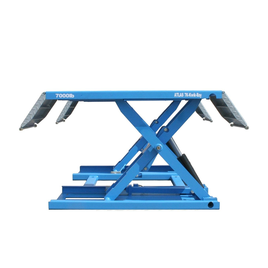
The electro hydraulic operation is described in detail in Chapter 8. Figure 1 – Lift This chapter describes the lift’s principal elements, allowing the user to be familiar with the machine. As shown in fi gure 1, the lift is composed of two Product Description Kwik Bay... - Page 13 N.2 wheels (8) can be installed on the lifts so that the lift can be mobile by means of a hook on the power unit carriage. Product Description Kwik Bay...
-
Page 14: Technical Specifi Cation
If there is over 10% fl uctuation on the electrical power supply, it is suggested to use the voltage stabilizer to protect the electrical components and system from overloading. Technical Specification Kwik Bay... - Page 15 Pump Type Gear Flow rate 2.1 cm Continuous Working pressure 3,335 psi. – 3,625 psi. Figure 2 - Layout Technical Specification Kwik Bay...
- Page 16 ASTM D 2270 Viscosity index 104 N° ASTM D 97 Pour point ~ 30 °C ASTM D 92 Flash point 215 °C ASTM D 644 Neutralization number 0.5 mg KOH/g Change hydraulic oil at 1 year intervals Technical Specification Kwik Bay...
- Page 17 Hydraulic cylinder Lowering solenoid valve Safety valve Gear pump Emergency hand pump - optional Motor Non return valve Oil fi lter Maximum pressure valve Figure 4 – Hydraulic Plan Technical Specification Kwik Bay...
- Page 18 Figure 5 – Electrical Wiring Diagram (120V-1Ph – 30 Amp Breaker Required) Power switch Circuit breaker Motor 1.8KW Transformer 63VA Overheat protector Lifting pushbutton Lowering pushbutton Locking pushbutton Contactor AC Lowering solenoid valve Locking solenoid air valve Timer Pilot lamp Rectifi er Technical Specification Kwik Bay...
- Page 19 Figure. 6 – Pneumatic Plan Technical Specification Kwik Bay...
-
Page 20: Safety
• be sure the motor of the vehicle is off, the gear engaged and the parking brake put on; • be sure only authorized vehicles are lifted without exceeding the maximum lifting capacity; • Verify that no one is on the platforms during lifting or standing. Safety Kwik Bay... - Page 21 Vehicle falling from the lift can be caused when the vehicle is improperly placed on platforms, and when its dimensions are incompatible with the lift or by excessive movement of the vehicle. In this case, keep immediately away from the working area. Safety Kwik Bay...
- Page 22 Any use of the lift other than that herein specifi ed can cause serious accidents to people in close proximity of the machine. Safety Kwik Bay...
-
Page 23: Installation
The lift must be placed on the concrete surface suffi ciently resistant. The surface must be suitable for bearing maximum stress values, also in unfavorable working conditions. The surface must be perfectly leveled. Hydraulic System Connection • Connect hydraulic hoses referring to Fig. 13; • Tighten fi ttings thoroughly. Installation Kwik Bay... - Page 24 • Make the electric hookup to the power unit referring to the attached the electric diagram fi gure 5 using the included electric cable. • Make sure the connection of the phases is right and lift is grounded. Installation Kwik Bay...
- Page 25 DO NOT continue pressing button after lift reaches full height. Damage to motor can occur if continued. • Repeat raise and lower the lift completely at least 3 times to equalize the oil pressure in each cylinder. Installation Kwik Bay...
- Page 26 Failure to do so can damage the lift severely. Carry out two or three complete cycles of lowering and lifting and check: • Repeat the 7.7 section • Check no strange noise during lifting and lowering Installation Kwik Bay...
-
Page 27: Operation And Use
The switch can be set in two positions: • 0 position: the lift electric circuit is not powered; the switch can be padlocked to prevent the use of the lift. • 1 position: the main electric circuit is powered Operation And Use Kwik Bay... - Page 28 It is extremely forbidden to load the vehicle when the mobile wheels are on the lift. Failure to do so can damage the lift severely. The lift must be raised at least 12” off of the ground before taking the load. Operation And Use Kwik Bay...
- Page 29 The Atlas® Kwik Bay mid-rise is designed to “QUICKLY” raise a vehicle to a desired height, perform the necessary service work, and then lower the vehicle to the ground WITHOUT engaging the pneumatic positive lock bar system. The pneumatic positive locking system will automatically engage in the unlikely event of a hydraulic failure while the vehicle is in the air.
- Page 30 • Attach the hook placed on the carriage to the hole placed on the front beam as shown in the fi gure 16. • Pull the carriage to move the lift. Fig. 15 Fig. 16 Operation And Use Kwik Bay...
- Page 31 (Fig. 17 - 2) anti-clockwise to lower the lift. The lowering speed can be controlled by turning the screw more turns or less; • Retighten the emergency screw by turning clockwise after lowering the lift completely. Operation And Use Kwik Bay...
-
Page 32: Maintenance
The use of water or infl ammable liquid is strictly forbidden. Be sure the rod of the hydraulic cylinders is always clean and not damaged since this may result in leakage from seals and, as a consequence, in possible malfunctions. Maintenance Kwik Bay... - Page 33 • a check of the electrical system to verify that Every motor, limit switch and control panel operate Electrical system properly must be carried out by skilled months electricians • empty the oil tank and change the hydraulic Maintenance Kwik Bay...
-
Page 34: Troubleshooting
Bleed the hydraulic system The lift does hydraulic circuit not lift or The pump fi lter is dirty. Check and clean if needed. lower smoothly The pump suction is blown Check the seal and replace if needed Troubleshooting Kwik Bay... -
Page 35: Parts List
32MF11 Nylon slider 32MF12 Spacer 32MG02 Lower safety rack 0215021 Greaser 8X1 0210016 Self-lubricated bush 3040 0212004 Seeger D.25-GB/T894.1 32ME13 Inner wheel 0210008 Self-lubricated bush 2520 0212021 Seeger D.30-GB/T894.1 0210039 Self-lubricated bush 2515 32ME12 Outer wheel Parts List Kwik Bay... - Page 36 0210010 Self-lubricated bush 2530 32M-70-0 Hydraulic cylinder 0210070 Edged self-lubricated bush 3030 4 32MI00 Lifting lever 0505018 Limit switch 8108 (At Request) 0206026 Screw M5X16 32MW10 Wheel support 32MW21 Wheel 32MW22 Wheel shaft 0212005 Seeger D.20-GB/T894.1 Parts List Kwik Bay...
- Page 37 Lift Parts List Kwik Bay...
- Page 38 Control Unit Parts List Kwik Bay...
- Page 39 Lowering push button LAY37-20 0502003 Lifting push button LAY37-10 0505028 Power switch 20A 0502023 Pilot lamp 24V 0503084 Transformer 63VA 220/380V 0503085 Transformer 63VA 230/400V 0501018 Timer relay AC24V 0504004 Fuse 4A 0504016 Fuse 1A 0507009 Wiring terminal 12 Parts List Kwik Bay...
- Page 40 Hydraulic Power Unit Parts List Kwik Bay...
- Page 41 Oil fi lter 3/8 0307012 Emergency hand pump 0306069 Union 8-1/8 (FN-8-01) 0306097 Rilsan hose 8X5 L=225mm 0305016 Plug 1/4 0309054 O-ring 17.0X1.8-GB3452.1 0309060 O-ring 115X3.55-GB3452.1 0305026 Oil level plug 3/8 0208006 SpringwasherD.8-GB/T93 0202045 Screw M8X80-GB/T70.1 Parts List Kwik Bay...
- Page 42 Item Part Number Description 0209030 Screw M6X8-GB/T78 0202045 Screw M8X20-GB/T70.1 0202033 Screw M6X20-GB/T70.1 0208005 Spring washer D.6-GB/T93 0205006 Washer D.6-GB/97.1 0307003 Lowering speed control valve 1.6 Parts List Kwik Bay...
- Page 43 Hydraulic Cylinder Parts List Kwik Bay...
- Page 44 Hydraulic hose L=390 0307021 Parachute valve 1/4 (At Request) 32M-70-2 Cylinder liner 32M-70-3 Cylinder shaft MS100-70-2 Piston 32M-70-1 Cylinder guiding cover 0212006 Seeger D.26-GB/T894.2 0312014 Gasket 70X50X22.4 0309025 O-ring 32X3.1–GB1235 0305007 Guide ring 38X10X2.5-GB/T15242.2 0311007 Scraper 38X46X5 Parts List Kwik Bay...
-
Page 45: Warranty
RETURNS: Products may not be returned without prior written approval from the Manufacturer. DUE TO THE COMPETITIVENESS OF THE SELLING PRICE OF THESE LIFTS, THIS WARRANTY POLICY WILL BE STRICTLY ADMINISTERED AND ADHERED TO. Warranty Kwik Bay...
Need help?
Do you have a question about the Kwik Bay and is the answer not in the manual?
Questions and answers