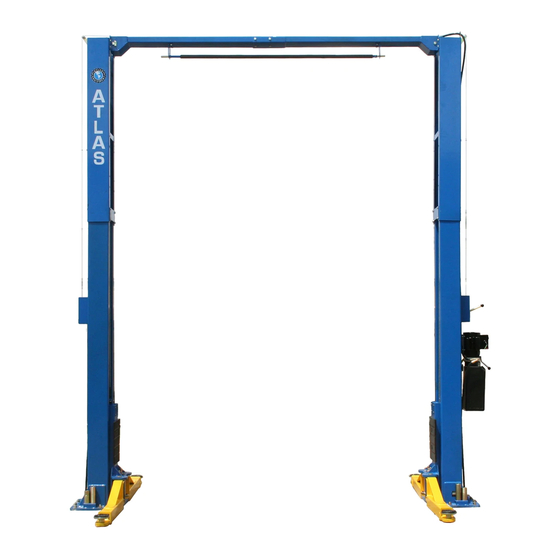
Atlas PV-12PX Installation & Operation Manual
12,000 lb. capacity two-post overhead lift
Hide thumbs
Also See for PV-12PX:
- Installation & operation manual (40 pages) ,
- Installation & operation manual (41 pages)
Table of Contents
Advertisement
Advertisement
Table of Contents

Related Manuals for Atlas PV-12PX


Summary of Contents for Atlas PV-12PX
- Page 2 Read this entire manual before operation begins. Record below the following information which is located on the serial number data plate. Serial No. Model No. Date of Installation...
-
Page 3: Table Of Contents
Trouble Shooting ... 42 Parts List For Model PV-12PX..43 Warranty ....49... -
Page 4: Specifi Cations
Specifi cations Clear-Floor Direct-Drive Model Features Model PV-12PX Features • Direct drive design, minimizes the lift wear parts and breakdown ratio • Dual hydraulic cylinders designed and made on ANSI standards utilizing NOK oil seals in the cylinders • Self lubricating UHMW Polyethylene sliders and bronze bushings •... - Page 5 115mm Floor 2.0 HP 12,000 12PX Direct- 72 1/2”–81 1/2” 150”/165”/177” 150 3/4” 123 1/2” 4 1/2” Drive Arm Swings View For Model PV-12PX 58 in 38 in 109-3/4 in 38 in 58 in 150-3/4 in Fig. 2 PV-12P Specifications...
-
Page 6: Installation Requirements
Installation Requirements Tools Required Rotary Hammer Drill (3/4in bit) Carpenter’s Chalk Hammer Screw Drivers 4 Foot Level Tape Measure (25ft) Crescent Wrench (12”) Pliers Ratchet & Socket (28mm) Allen Head Wrench (3mm, 5mm, 8mm) Wrench set (mm) Vise Grips (10#, 13#, 14#, 15#, 17#, 19#, 24#, 27#, 30#) Fig. - Page 7 Concrete Specifi cations Concrete specifi cations must be followed accordingly. Failure to do so may result in lift and/or vehicle falling. 1. Concrete must be 6 inches minimum and must be totally cured before lift installation. 2. Concrete must be in good condition and must have a test strength 3,500psi minimum.
-
Page 8: Installation Steps
Installation Steps A. Installation Location - Double check the installation site (concrete, layout, space size etc.) for the lift installation. B. Use a carpenter’s chalk line to establish installation layout for the base plates. Fig. 5 PV-12P Installation Steps... - Page 9 C. Check the parts before assembly. 1. Packaged lift, hydraulic power unit and parts box. Fig. 6 2. Move the lift aside with a fork lift or hoist, and open the outer packing carefully. Nameplate Top Connection Shipment Assembly Parts list Fig.
- Page 10 4. Lift the upper column with a fork lift or hoist. Loosen the bolts on the upper package stand. Remove off the upper outer column. Remove the parts in the inner column. Fig. 9 5. Lift the lower column with a fork lift or hoist. Remove the package stand. Remove the lower column.
-
Page 11: 7. Open The Carton Of Parts And Check The Parts According To Parts Box List
6. Move aside the parts and check the parts according to the shipment parts list. Fig. 11 7. Open the carton of parts and check the parts according to parts box list. Fig. 12 PV-12P Installation Steps... - Page 12 8. Check the parts in parts bag 1# according to parts bag list. Fig. 13 9. Check the parts in parts bag 2# according to parts bag list. Fig. 14 PV-12P Installation Steps...
- Page 13 D. Install the hydraulic hose and lock release cable brackets on the extension columns. Use M6 x 20 Hex Bolts with M6 Nylock Nut & M6 Washer Fig. 15 PV-12P Installation Steps...
- Page 14 E. Install hydraulic cylinders Connect the extended straight fi tting and 90° fi tting. Install the cylinders through the carriages. Off side column Power side column Use Tefl on tape to seal pipe threads. Do not use tefl on tape on hydraulic hose ends. Fitting towards the hole of the column Fig.
- Page 15 F. Install columns (Use M12 x 30 Hex Bolt, Nylock Nut & Washer to install extensions) Lay down the two columns on the installation site parallel of each other. Position the power side column according to the actual installation site. This lift is designed with 2 sectional columns.
- Page 16 2. When the ceiling height is over 4200mm (165 3/8”) but less than 4500mm (177 1/8”), connect the outer columns to the middle holes. Fig. 18 Low Setting PV-12P Installation Steps...
- Page 17 3. When the ceiling height is less than 4200mm (165 3/8”), connect the outer columns to the upper holes. The cables are a special order option for the extra low setting. Fig. 19 Special low Setting PV-12P Installation Steps...
- Page 18 G. Position columns 1. Position the columns so the base plates line up with the chalk line. It is recommended to install the power side column on the passenger side of the vehicle. Meanwhile, assemble the overhead top beam. Spread the columns to approximately 122-5/8”...
- Page 19 H. Install overhead top beam 1. With help of the hooks on the top beam, hang the top beam on top of the extension columns and connect the top beam to the extension columns with bolts, tighten the bolts. Hook on to the extension columns Use M12 x 30 Hex Bolts with M12 Nylock...
- Page 20 2. Assemble the over head top beam; tighten the anchor bolts. Use M12 x 30 Hex Bolts with M12 Nylock Nuts and Washers Fig. 22 PV-12P Installation Steps...
- Page 21 I. Install the limit control bar and limit switch. Loosen Screw on Drive Use M12 x 30 Hex Bolts with Rod for adjustment, M12 Nylock Nuts and Washers Tighten the screw to install control bar brackets after adjustment Adjust Drive Rod of Limit Switch Limit Switch connected...
- Page 22 J. Install safety device. 145° Spring Fig. 24 Power side safety device Use M10 x 10 Allen Head Set Screw 145° Spring 120° Spring Use M10 x 20 Hex Fig. 25 Offside safety device Head Bolts to secure the pulley bracket PV-12P Installation Steps...
- Page 23 K. Lift the carriages up by hand and lock them at the same level. Fig. 26 PV-12P Installation Steps...
- Page 24 L. Install cables 1. High setting cable connection, suitable for ceiling height over 4500mm (177 -1/8”). 1.1 Take out the carriages’ plastic covers, cable passes through from the bottom of the carriages and pulled out from the openings of the carriages, then screw the two cable nuts.
- Page 25 1.2 Connecting the cable for high setting. High Setting Cable 2 Cable 1 Cable 2 Fig. 28 PV-12P Installation Steps...
- Page 26 2. Low setting cable connection, suitable for ceiling heights between 4200mm (165 3/8”) to 4500mm (177 1/8”). Low Setting Cable 2 Cable 1 Cable 2 Fig. 29 PV-12P Installation Steps...
- Page 27 3. Special low setting cable connection, suitable for ceiling height less than 4200mm (165 3/8”), for this setting use with the optional short cable. Special Low Setting Cable 2 Cable 1 Cable 2 Fig. 30 PV-12P Installation Steps...
- Page 28 M. Install power unit. Use M8 x 25 Hex Bolts with M8 Nuts & Washers Fig. 31 PV-12P Installation Steps...
- Page 29 N. Install oil hoses. 1. At high setting and low setting oil hose connection. 2. Special low setting oil hose connection. Limit switch Oil hose Oil hose passes through the retainer on top of the overhead beam Oil hose connected with 90°...
- Page 30 O. Install safety cable. Install the safety cable from the off side safety assembly to the power side safety assembly. Safety cable Safety cable passes through small pulley bracket Install safety cable from offside safety assembly. Safety cable connected with the power Fig.
- Page 31 P. Install hose retainers. Install oil hose retainers using M6 x 8 screws Car in direction Fig. 35 PV-12P Installation Steps...
- Page 32 Q. Install the lifting arms. Lower the carriages down to the lowest position, then use the 8mm Allen head wrench to loosen the socket bolt (See Fig.37). Adjust arm lock as direction of arrow (See Fig.38). Adjust the moon gear and arm lock so they mesh, then tighten the Allen bolts on the arm lock (See Fig.39).
- Page 33 Connect the power source according to the data plate on the Power Unit. Remove the short “Pig Tail” wire connected to the AC contactor terminals. This wire was used to test the motor after production. ATLAS Single phase motor Four Terminal Relay 1) Motor Lead a) M1 to “YELLOW”...
-
Page 34: Exploded View
Exploded View Model PV-12PX Fig. 48 PV-12P Exploded View... - Page 35 Cylinders Fig. 49 PV-12P Exploded View...
- Page 36 Atlas Manual Power Unit 220V/60HZ, Single Phase Fig. 50 PV-12P Exploded View...
- Page 37 Illustration Of Atlas Hydraulic Power Unit ATLAS manual power unit, 220V/60HZ, Single phase Fig. 51 PV-12P Exploded View...
-
Page 38: Test Run
Test Run 1. Adjust equalizing cables Cable nut Use a wrench and hold the cable fi tting, meanwhile use a wrench to tighten the cable nut. Make sure the two cables have the same tension and the two carriages lift at the time. Lock nut Replace the plastic cover on the lifting head. - Page 39 4. Adjust the lower speed (Only for PEAK power unit) (Adjust with a load on the lift) You can adjust the lowering speed of the lift if necessary: Loosen the locking nut on the throttle valve, and then turn the throttle valve clockwise to decrease the lowering speed, or counterclockwise to increase the lowering speed.
-
Page 40: Operation Instructions
Operation Instructions Please read the safety tips carefully before operating the lift To lift vehicle 1. Be sure there are no obstructions near the lift area; 2. Position lift arms to the lowest position; 3. Open lift arms; 4. Position vehicle between columns; 5. -
Page 41: Maintenance Schedule
Maintenance Schedule Monthly: 1. Re-torque the anchor bolts to 65-86 Ft Lbs; 2. Check all connectors, bolts, pulleys and pins; 3. Lubricate cable with lubricant; 4. Make a visual inspection of all hydraulic hoses/lines for possible wear or leakage; 5. Check the condition of the safety lock device; 6. -
Page 42: Trouble Shooting
Trouble Shooting TROUBLE CAUSE REMEDY 1. Button does not work 1. Replace button 2. Wiring connections are not in good 2.Repair all wiring condition connections Motor does not 3. Motor burned out 3. Repair or replace motor 4. Height limit switch is damaged 4.Replace the limit switch 5. -
Page 43: Parts List For Model Pv-12Px
Parts List For Model PV-12PX Item Part# Description Qty. Note 217001B Power side column 209002A Power unit 209003 Bolt 209033 Lock washer 209005 Self locking Nut 217003 Power side lock cover 217004 Main cam lock 217069 Hex Bolt 206006 Washer... - Page 44 Snap ring 520023 Lock washer 209039 Washer 209022 Moon gear 206049 217052C Lifting arm 217120 Outer arm 217121A Inner arm 206048 Socket bolt 206032 Snap clip 640109 Washer 206036 Roll pin 217044 Arm lock PV-12P Parts List For Model PV-12PX...
- Page 45 206023A Hex Nut 217005 Plastic ball 217006 Lock handle 217007 Large spacer 217030 Main spring 217009 Main lock 217010 Hex Bolt 217011 Hex Nut 217012 Small spacer 217050 Main lock pin 217051 Socket bolt PV-12P Parts List For Model PV-12PX...
- Page 46 Parts box For optional short cable and hose 217112 Short cable Parts For Hydraulic Cylinder 61-1 209069 O-Ring 61-2 209070 Bleeding Plug 61-3 209071 Support Ring 61-4 209072 Y-Ring 61-5 209073 O-Ring 61-6 209074 Piston PV-12P Parts List For Model PV-12PX...
- Page 47 Item Part# Description Qty. Note 61-7 209075 O-Ring 61-8 217089 Piston rod 61-9 217077 Piston rod fi tting 61-10 209078 Dust ring 61-11 209079A Head cap 61-12 217080A O-Ring 61-13 217090 Bore Weldment PV-12P Parts List For Model PV-12PX...
- Page 48 Parts For ATLAS Manual Power Unit, 220V/60Hz, Single phase 201-1 81400032 Motor 201-2 81400159 Protective Ring 201-3 81400063 Motor Connecting Shaft 201-4 81400031 Valve Body 201-5 81400160 Relief Valve 201-6 81400161 Lock Washer 201-7 81400162 Socket Bolt 201-8 81400121 Inlet Pipe...
-
Page 49: Warranty
Warranty This item is warranted for fi ve (5) years on structural components, two (2) years on hydraulic cylinders, and one (1) year on electric or air / hydraulic power units from invoice date. Wear items are covered by a 90 day warranty. This LIMITED warranty policy does not include a labor warranty.
Need help?
Do you have a question about the PV-12PX and is the answer not in the manual?
Questions and answers
how much concrete do we need on each side of the post
The Atlas PV-12PX requires a minimum of 6 inches of concrete thickness on each side of the post.
This answer is automatically generated