Atlas PV-15PX Installation & Operation Manual
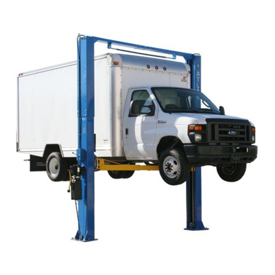
15,000 lb. capacity two-post overhead lift
Hide thumbs
Also See for PV-15PX:
- Installation and operation manual (39 pages) ,
- Installation & operation manual (41 pages)
Table of Contents
Advertisement
Quick Links
Advertisement
Table of Contents

Related Manuals for Atlas PV-15PX


Summary of Contents for Atlas PV-15PX
- Page 2 Revised 5/15/2020 Read this entire manual before operation begins. Record below the following information which is located on the serial number data plate. Serial No. Model No. Date of Installation...
-
Page 3: Table Of Contents
Contents General Information..5 Product Identifi cation ..8 Packing, Transport, Storage ..9 Lift Description ... . 11 Technical Specifi... - Page 4 PRINTING CHARACTERS AND SYMBOLS Throughout this manual, the following symbols and printing characters are used to facilitate reading: Indicates the operations which need proper care Indicates prohibition Indicates a possibility of danger for the operators BOLD TYPE Important information WARNING: before operating the lift and carrying out any adjustment, read carefully chapter 7 “installation”...
-
Page 5: General Information
General Information This chapter contains warning instructions to operate the lift properly and prevent injury to operators or objects. This manual has been written to be used by shop technicians in charge of the lift (operator) and routine maintenance technician (maintenance operator). The operating instructions are an integral part of the machine and must remain with it for its whole useful life. - Page 6 Obligation In Case Of Malfunction In case of machine malfunction, follow the instructions contained in the following chapters. Cautions For The Safety Of The Operator Operators must not be under the infl uence of sedatives, drugs, or alcohol when operating the machine. Before operating the lift, operators must be familiar with the position and function of all controls, as well as with the machine features shown in the chapter “Operation and Use”...
- Page 7 Declaration Of Warranty And Limitation Of Liability The manufacturer has paid proper attention to the preparation of this manual. However, nothing contained herein modifi es or alters, in any way, the terms and conditions of manufacturer agreement by which this lift was acquired, nor increase, in any way, manufacturer’s liability to the customer.
-
Page 8: Product Identifi Cation
Product Identifi cation The identifi cation data of the machine are shown in the serial plate placed on the power side column. The removal of the serial plate is strictly forbidden. Machines may be updated or slightly modifi ed from an aesthetic point of view and, as a consequence, they may present different features from these shown, this without prejudicing what has been described herein. -
Page 9: Packing, Transport, Storage
Packing, Transport, Storage Only skilled personnel who are familiar with the lift and this manual shall be allowed to carry out packing, lifting, handling, transport and unpacking operations. Packing The packing of the lift is delivered in following components: • N. 1 base unit packed in a steel frame, wrapped up in non-scratch material, including the accessory box and the power unit. - Page 10 Lifting And Handling When loading/unloading or transporting the equipment to the site, be sure to use suitable loading (e.g. cranes, trucks) and hoisting means. Be sure also to hoist and transport the components securely so that they cannot drop, taking into consideration the package’s size, weight and center of gravity, and its fragile parts.
-
Page 11: Lift Description
Lift Description The lift is suitable for lifting motor vehicles having maximum weight as described in the nameplate on the power side column of the lift. All mechanical parts such as columns, carriages, and lift arms have been built in steel plate to make the frame stiff and strong while keeping a low weight. -
Page 12: Technical Specifi Cation
Technical Specifi cation Size And Main Features CAPACITY 15,000lbs (6800kg) Max. lifting height 75 1/8” (1908mm) Min. lowered height 7 1/4” (183mm) Overall height - special low setting 152 1/2” (3872mm) Requires purchase of additional shorter cables Overall height - lower setting 164 7/8”... - Page 13 Figure 3 – Layout PV-15P Technical Specification...
- Page 14 Hydraulic Power Unit Figure 4 – Hydraulic Power Unit Use wear proof oil for hydraulic drive, in conformity with ISO 6743/4 rules (HM class). The oil with features similar to those shown in the table is recommended. Test standards Features Value ASTM D 1298 Density 20°C...
- Page 15 Figure 5 - Hydraulic Plan Oil fi lter Hydraulic cylinder Gear pump Manual lowering valve Motor Flow restrictor Non return valve Startup valve Pressure overload valve (Max. 250 bar) PV-15P Technical Specification...
- Page 16 Figure 6a – Electrical Diagram (400V/380V/50Hz/60Hz/3Ph) PV-15P Technical Specification...
- Page 17 Figure 6b – Electrical Diagram (220V/50Hz/60Hz/1Ph) PV-15P Technical Specification...
-
Page 18: Safety
Safety Read this chapter carefully and completely because it contains important information for the safety of the operator and the person in charge of maintenance. The lift has been designed and built for lifting vehicles and making them stand above level in a closed area. Any other use is forbidden. - Page 19 • Be sure only authorized vehicles are lifted without exceeding the maximum lifting capacity; • Verify that no one is on the arms during lifting or standing. Safety Device To avoid overloading and possible breaking, the following safety devices have been used: •...
- Page 20 Safety Signs All safety warning signs (ref. fi gure 7) displayed on the lift are with the purpose to draw the operator’s attention to dangerous or unsafe situations. The labels must be kept clean and they have to be replaced if detached or damaged. Read the meaning of the labels carefully and memorize it.
-
Page 21: Installation
Installation Only skilled technicians, appointed by the manufacturer, or by authorized dealers, must be allowed to carry out installation. Serious damage to people and to the lift can be caused if installations are made by unskilled personnel. Always refer to the exploded views attached during installation. Tool Required Rotary Hammer Drill D.19 Hex-Key/Allen Wrench Set... - Page 22 Floor Requirement The lift MUST be installed on 3000 PSI concrete with the minimum thickness 6” and an extension of at least 4’ from anchoring points. New concrete must be adequately cured by at least 21 days minimum. Specifi cations of concrete must be adhered to. Failure to do so could cause lift failure resulting in personal injury or death.
- Page 23 Anchoring Columns The requirements for column’s square-ness and plumb must be adhered to. Failure to do so could cause lift failure resulting in personal injury or death. • Use the base plate on the column as the guide, drill each hole in the concrete approximately 6”...
- Page 24 • Place the anti-crushing bar on the bracket and fi x it on another bracket using M8X40 screw and nuts; • Use a lifting device to raise the assembled beam and install it to the column extensions as shown. The beam has the hook on each end to aid the installation;...
- Page 25 7.10 Routing Equalizer Cables • Use an appropriate lifting equipment to raise the carriage to the fi rst latch position. Be sure the carriage is engaged securely before attempting to route the equalizer cables. Carriages must be equal height from the fl oor before proceeding;...
- Page 26 7.11 Routing Latch Release Cable • Install the top pulley brackets on both column extensions as shown; • Route the straight end of the latch release cable (the end without the loop) through the hole in the offside latch, down under the cable guide, over the bracket at the top of the offside column, over and down the bracket on the power-side column, and through the latch on the lock release on this side;...
- Page 27 7.13 Connection Of Hydraulic Hoses When routing the hydraulic hose, make sure that the hose is clear of any moving part. Make sure to keep the hoses clean from dust. Make sure not to over-tighten the hose fi ttings so as to result in oil leakage.
- Page 28 7.14 Make The Electrical Connection The hookup work must be carried out by a qualifi ed electrician. Make sure that the power supply is right. Make sure the connection of the phases is right. Improper electrical hook-up can damage motor and will not be covered under warranty.
- Page 29 • If latches click out of synchronization, tighten the cable on the one that clicks fi rst; • Fill with more fl uid if necessary till the tank is full. 7.16 Installation Of Arms • Raise the carriages to a convenient height; •...
- Page 30 7.17.3 EQUALIZER CABLE FOR PROPER INSTALLATION The equalizer cables should be checked weekly for equal tension. Failure to do this will cause uneven lifting. The cables should always be adjusted so that they are equal tension when resting on the safety locks. •...
- Page 31 7.18 Check With Load WARNING: please follow carefully the instructions in the coming paragraph for avoiding damages on the lift. Carry out two or three complete cycles of lowering with the vehicle loaded: • Repeat the checks provided for by 7.17. •...
-
Page 32: Operation And Use
Operation And Use NEVER operate the lift with any person or equipment below. NEVER exceed the rate lifting capacity. NEVER lift a vehicle in any manner with less than four arms. Always ensure that the mechanical locks are engaged before any attempt is made to work on or near the vehicle. - Page 33 Lift operation can be summarized into four steps: Vehicle Positioning • Positioning the vehicle between columns; • Adjust lift arms so that the vehicle is positioned with the center gravity between the pads. Make sure the arm safeties are engaged; •...
-
Page 34: Maintenance
Maintenance Only trained people who know how the lift works, can be allowed to service the lift. To service properly the lift, the following has to be carried out: • Use only genuine spare parts as well as equipment suitable for the work required;... - Page 35 Periodic Maintenance • Check hydraulic connections and hoses for leaks • Check mechanical locks audibly and visually while in operation Daily pre-operation • Check arm locks • Check bolts, nuts and screws are tight • Check all cable connections, pins and bolts to insure proper mounting •...
-
Page 36: Troubleshooting
Troubleshooting A list of possible troubles and solutions is given below: Trouble: Possible Cause: Solution: Check Power on to restore if There is no power necessary The electrical wires are Reconnect The lift does not work disconnected Check for correct voltage The circuit breaker are blown Replace... -
Page 37: Parts List
Parts List Overhead Beam Assembly Overhead Beam Assembly Item Part No. Description Z23M112000 Column extension 0206036 Screw M6X8 Z23G150202 Pipe clamp 0201014 Screw M6X20 0205006 Washer D.6 0208005 Spring washer D.6 0203035 Nut M6 Z23G132000 Wire roller assembly Z23G150201 Cable relief Z23G410001 Pulley shaft PV-15P... - Page 38 Overhead Beam Assembly Item Part No. Description Z23G410004 Spacer XSZ-1-02-11 Upper pulley 0210007 Bush SF-1/2518 Z23G410003 Spacer 0202032 Screw M6X16 Z23G413000 Restric shelf 0606024 Cable relief D.16 0203023 Nut M12 0208009 Spring washer D.12 0205013 Washer D.12 0201148 Screw M12X40 Z23G410002 Anti-rotation plate 0205011...
- Page 39 Power Side Column Assembly Power-Side Column Assembly Item Part No. Description Z23M101000 Power-side column XSZ-7-5-3 Adaptor extension H.150 XSZ-7-5-2 Adaptor extension H.75 XSZ-7-5-1 Adaptor extension H.50 0302019 Hydraulic power unit 220V60Hz1ph 0205011 Washer D.10 0208007 Spring washer D.10 0201062 Screw M10X20 Z23G150202 Pipe clamp 0206036...
- Page 40 Power-Side Column Assembly Item Part No. Description 0203023 Nut M12 Z23M112000 Column extension Z23G121100 Pulling plate 0201081 Screw M12X60 Z23MY60000 Hydraulic cylinder unit Z23G520100 Equalizer steel cable 0205020 Washer D.16 0203025 Nut M16 0204032 Nut M16 Z23M201000 Carriage assembly Z23G530100 Arm shaft Z23M310000 Arm assembly...
- Page 41 Power-Side Column Assembly Item Part No. Description 0313078 Seeger LDQ-60X70X2-PTFE 0310021 Sealing ring 60X70X7 0305012 Guide ring 60X12X2.5 0309098 O-ring 69X3.55 0309097 O-ring 42.5X3.55 0212039 Seeger D.60 0305044 Seal support ring 63X56X12 0313001 Washer BS/A13.70 PV-15P Parts List...
- Page 42 Power-Side Column Power-Side Column Item Part No. Description Z23M111000 Column weldment 0210007 Bush SF-1/2518 Z23G110201 Cable pulley Z23G110100 Pulley shaft 0205008 Washer D.8 0208006 Spring washer D.8 PV-15P Parts List...
- Page 43 Power-Side Column Item Part No. Description 0201026 Screw M8X16 Z23G140301 Latch shaft Z23G140305 Spacer 0204024 Nu M6 0201174 Screw M8X25 0213052 Pin 6X40 Z23A110200 Cam plate Z23G140100 Lock latch Z23G140303 Return spring 2 Z23G140304 Spacer 0203032 Nut M10 Z23G140201 Handle 0215017 Ball M10X33 0209028...
- Page 44 Off-Side Column Assembly Off-Side Column Assembly Item Part No. Description Z23M102000 Off-side column XSZ-7-5-3 Adaptor extension H.150 XSZ-7-5-2 Adaptor extension H.75 XSZ-7-5-1 Adaptor extension H.50 0201148 Screw M12X40 0205013 Washer D.12 0208009 Spring washer D.12 0203023 Nut M12 Z23M112000 Column extension 0206036 Screw M6X8 Z23G150202...
- Page 45 Off-Side Column Assembly Item Part No. Description 0201081 Screw M12X60 Z23MY60000 Hydraulic cylinder Z23G520100 Equalizer steel cable 0205020 Washer D.16 0203025 Nut M16 0204032 Nut M16 Z23M201000 Carriage assembly Z23G530100 Arm shaft Z23M310000 Arm assembly Z23N330000 Adaptor assembly Z23N331000 Pad support Z31B330001 Rubber pad 0202032...
- Page 46 Off-Side Column Assembly Item Part No. Description 0309098 O-ring 69X3.55 0309097 O-ring 42.5X3.55 0212039 Seeger D.60 0305044 Seal support ring 63X56X12 0313001 Washer BS/A13.70 PV-15P Parts List...
- Page 47 Off-Side Column Off-Side Column Item Part No. Description Z23M121000 Column weldment 0210007 Bush SF-1/2518 Z23G110201 Cable pulley Z23G110100 Pulley shaft 0205008 Washer D.8 0208006 Locking washer D.8 0201026 Screw M8X16 Z23G140305 Spacer Z23G140302 Return spring 1 0204024 Nut M6 0201174 Screw 8×25 PV-15P Parts List...
- Page 48 Off-Side Column Item Part No. Description 0213052 Pin 6X40 Z23A110200 Cam plate Z23G140100 Lock latch Z23G140303 Return spring 2 Z23G140304 Spacer Z23G140301 Latch shaft 0209028 Screw M10X16 0206036 Screw M6X8 0205006 Washer D.6 Z23G122200 Latch cover 0206032 Screw M6X16 0208005 Spring washer D.6 Z23G131001 Roller bracket...
- Page 49 Carriage Carriage Item Part No. Description Z23M210100 Carriage Z23G221101 Slider XSZ-8-802-2 Rubber protection 0205006 Washer D.6 0202032 Screw M6X16 Z23G240101 Front cover 0206036 Screw M6X8 Z23G231100 Arm lock release pin Z23G231201 Spring Z23A200003 Toothed gear 0212004 Seeger D.25 0213052 Pin 6X40 PV-15P Parts List...
- Page 50 Arm Assembly Arm Assembly Item Part No. Description Z23M311000 Short arm frame – single extension Z23M312000 Short arm outer extension 0201059 Screw M10X16 0208007 Spring washer D.10 0205011 Washer D.10 Z23A310001 Anti-rotating gear 0201068 Screw M10X40 PV-15P Parts List...
- Page 51 Hydraulic Line Hydraulic Line Item Part No. Description Hydraulic power unit 0302019 220V60Hz1ph WW(5/16)5200 W(04-05) Hydraulic hose L=5200 ZZ(5/16)6160 Z(04-05) Hydraulic hose L=6160 0303021 Union AB-04 Z23MY60000 Hydraulic cylinder unit 0303123 Union BZ-JT-016 Cylinder union 0313001 Washer BS/A13.70 6246-Y1.8 Flow restrictor 7530-Y-3 Spring Z54YY18001...
- Page 52 Hydraulic Line Item Part No. Description Z23MY62000 Cylinder liner 0313001 Washer BS/A13.70 0305065 Oil plug 4BN-04 G1/4 0305044 Seal support ring 63X56X12 0212031 Seeger D.55 Z23MY61002 Cylinder shaft 0309097 O-ring 42.5X3.55 Z23MY61001 Shaft head 0309098 O-ring 69X3.55 0305012 Guide ring 60X12X2.5 0310021 Sealing ring 60X70X7 0313078...
-
Page 53: Warranty
Warranty This item is warranted for fi ve (5) years on structural components, two (2) years on hydraulic cylinders, and one (1) year on electric or air / hydraulic power units from invoice date. Wear items are covered by a 90 day warranty. This LIMITED warranty policy does not include a labor warranty.
Need help?
Do you have a question about the PV-15PX and is the answer not in the manual?
Questions and answers