Table of Contents
Advertisement
Quick Links
Advertisement
Table of Contents

Related Manuals for Atlas Pro-9D


Summary of Contents for Atlas Pro-9D
- Page 1 9,000 POUND CAPACITY MODEL: PRO - 9 D Page 1 of 36...
- Page 2 TWO-COLUMN AUTOMOTIVE LIFT READ THIS ENTIRE MANUAL BEFORE OPERATION BEGINS RECORD BELOW THE FOLLOWING INFORMATION WHICH IS LOCATED ON THE SERIAL NUMBER DATA PLATE Serial No. Model Date of Install RECORD BELOW THE FOLLOWING CUSTOMER INFORMATION Company Name Contact Person Street Address City State...
-
Page 3: Table Of Contents
Table of Contents Important Information....................4 Specifications……......................6 Installation Requirements....................8 Tools Required………………………………................9 Installation Procedure……….....................9 Safety Cable Routing…………………………………………………………………………......13 Wiring Instructions......................15 Lift Lockout/Tagout Procedure..................18 Operating Instructions……………..................20 Safety Procedures......................21 Preventive Maintenance....................22 Troubleshooting…………………...................25 Pro-9D Exploded Drawing………..................28 Pro-9D Parts List……………....................29 Warranty………………………………………………………….............32 Page 3 of 36... -
Page 4: Important Information
Important Information 1. Any freight damage must be noted on the freight bill before signing and reported to the freight carrier with a freight claim established. Identify the components and check for shortages. If shortages are discovered, please Contact the Distributor / Sales Rep. in your area for service. - Page 5 PRO-9D IMPORTANT INFORMATION This is a vehicle lift installation/operation manual and no attempt is made or implied herein to instruct the user in lifting methods particular to an individual application. Rather, the contents of this manual are intended as a basis for operation and maintenance of the unit as it stands alone or as it is intended and anticipated to be used in conjunction with other equipment.
- Page 6 PRO-9D SPECIFICATIONS Capacity 9,000 lbs. Lifting Time 45 Seconds Overall Height 144" (w/ brackets) Overall Width w/ Power Unit 140" Between Columns 109 3/4" Drive Through 92 1/4” Height Shut-Off 134 1/2" Page 6 of 36...
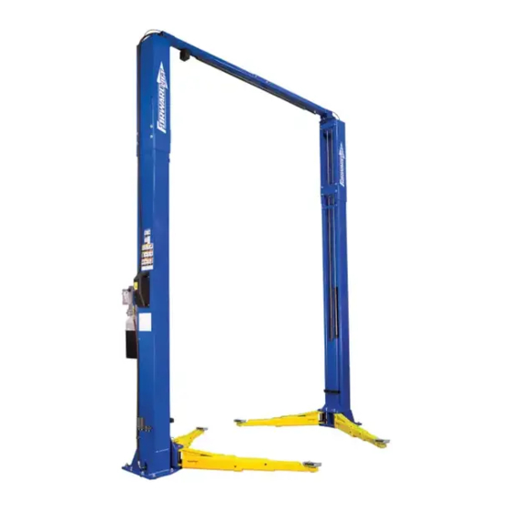
- Page 7 ASYMMETRICAL ARM CONFIGURATON Page 7 of 36...
- Page 8 NOTE: Lift can be installed so power unit column can be located on either side. However, to save operation steps it is recommended that it is placed on passenger side of lift. Page 8 of 36...
-
Page 9: Installation Requirements
INSTALLATION REQUIREMENTS 1. Concrete shall have compression strength of at least 3,000 PSI and a minimum thickness of 4” in order to achieve a minimum anchor embedment of 3 1/4”. NOTE: When using the standard supplied 3/4” x 5 1/2" long anchors; if the top of the anchor exceeds 2 1/4”... -
Page 10: Tools Required
Tools Required The installation of this lift is relatively simple and can be accomplished by two men in a few hours. The following tools and equipment are needed: • Hoist or Forklift (optional) • Metric Sockets and Open Wrench set •... - Page 11 NOTE: the power unit column can be located on either side. It is helpful to try and locate the power side with the passenger side of the vehicle when loaded on the lift to save steps during operation. 6. Unpack the cylinders and open the oil port on each cylinder by unscrewing the black plastic cap.
- Page 12 • Use a concrete hammer drill with a carbide tip, solid drill bit the same diameter as the anchor, 3/4”. (.775 to .787 inches diameter). Do not use excessively worn bits or bits which have been incorrectly sharpened. • Keep the drill in a perpendicular line while drilling. •...
- Page 13 11. Set carriages on the first safety latch engagement. Be sure each carriage is at the same height by measuring from the top of the base to the bottom of the carriage (double check the latches before working under the carriages). This dimension should be within 1/4”.
- Page 14 Page 14 of 36...
- Page 15 17. Mount the power unit on the main side leg to the power unit bracket using the four 5/16” bolts and nuts. Connect the power unit to the fitting installed on the back of the main leg. 18. Connect the equalizing cables.
- Page 16 Adjust each cable to approximately ½” side-to-side play. Check the latch/lock release to ensure the carriages are still engaged on the appropriate lock. 20. Connect the Hydraulic Hoses and Fittings. 21. Install remaining anchors at this point using directions from page 8. 22.
- Page 17 2. Disconnect Electrical Power Before Installation Now you are ready to connect the Push Button “UP” wire to one of the 2 wires remaining in the overhead shut off wire bundle. Remove Push Button “UP” wire from terminal 1. Cut some length off the wire.
- Page 18 Disconnect Electrical Power Before Installation NOTE: Before placing a vehicle on the lift, cycle the Lift up and down several times to ensure that the lock latches engage properly and that all air is removed from the system. To lower the lift, first raise the lift clear of the lock latches and then pull down the safety release handle and depress the hydraulic release on the power unit.
-
Page 19: Lift Lockout/Tagout Procedure
Lift Lockout/Tagout Procedure Purpose This procedure establishes the minimum requirements for the lockout of energy that could cause injury to personnel by the operation of lifts in need of repair or being serviced. All employees shall comply with this procedure. Responsibility The responsibility for assuring that this procedure is followed is binding upon all employees and service personnel from outside service companies (i.e., Authorized... -
Page 20: Operating Conditions
a. If this is a lockable device, the authorized lockout person places the assigned padlock on the device to prevent its unintentional reactivation. An appropriate tag is applied stating the person’s name, at least 3” x 6” in size, an easily noticeably color, and states not to operate device or remove tag. - Page 21 Read operating and safety procedures manual completely before operating lift. • Properly maintain and inspect lift in accordance to owner’s manual. • Do not operate a lift that is damaged or in need of repair. • Allow only authorized personnel in the lift bay. •...
-
Page 22: Safety Procedures
• Unload lift by first completely lowering lift, then swinging arms to drive-thru position before moving vehicle. WARNING!!! Always make sure latches on both sides clear the rack at same time when pulling down the release handle by adjusting the cable. Lift Points Note: Refer to the manufacturer’s specific vehicle lifting points. - Page 23 comes sooner. Periodic maintenance is to be performed on a daily, weekly, and yearly basis as given in the following paragraphs WARNING!! Occupational Safety and Health Administration (OSHA) and the American National Standards Institute (ANSI) requires users to inspect lifting equipment at the start of every shift.
-
Page 24: Yearly Maintenance
Weekly Maintenance (every 40-Hours) 1. Check anchor bolts torque to 110 ft-lbs for the ¾ in. anchor bolts. Do not use an impact wrench to tighten anchor bolts. 2. Check floor for stress cracks near anchor bolts. 3. Check hydraulic oil level. 4. - Page 25 CAUTION!! Relocating or changing components may cause problems. Each component in the system must be compatible; an undersized or restricted line will cause a drop in pressure. All valve, pump, and hose connections should be sealed and/or capped until just prior to use. Air hoses can be used to clean fittings and other components.
-
Page 26: Troubleshooting
Troubleshooting The common problems that may be encountered and their probable causes are covered in the following paragraphs: Page 26 of 36... - Page 27 Page 27 of 36...
- Page 28 Page 28 of 36...
-
Page 29: Pro-9D Exploded Drawing
Pro-9D Exploded Drawing Page 29 of 36... - Page 30 PART LIST OF PR0-9D QL5M-2R1-00 RIGHT COLUMN WELDMENT GROUP QL5M-2L1-00 LEFT COLUMN WELDMENT GROUP QL5M-1R0-00 RIGHT EXTEND COLUMN GROUP QL5M-1 L0-00 LEFT EXTEND COLUMN GROUP GB5782-86 HEXAGONAL HEAD BOLT M12*40 GB93-87 LOCK WASHER 12 GB97.1-85 FLAT WASHER 12 GB6170-86 HEXAGON NUTS M12 QL4L-000-08 PULLEY STAND...
- Page 31 QL4L-000-14 BOLT OF TOP QL4L-000-12 TOP ROD STAND GB93-87 LOCK WASHER 8 GB6170-86 NUTM8 QL4L-700-L0 LEFT HOSE BRACKET QL4L-510-00 COVER WELDMENT QL4L-000-05 TUBING CLAMP GB818-85 BOLT M6*6 QL41-000-01 PRESSING PLATE PART LIST OF PR0-9D QL40-000-15 ANCHOR BOLT QL4L-600-00 CABLE QL40-700-01 THICK PULLEY QL4M-220-00...
- Page 32 QL4L-000-21 POWER UNIT QL40-000-07 90 DEGREE FITTING "O" RING QL4L-000-02 HYDRAULIC HOSE GB5782-86 BOLT M8*25 GB97.1-85 FLAT WASHER 8 QL4L-000-01 FITTING GB97.1-85 FLAT WASHER 14 GB6170-86 NUT 9/16 GB6172-86 NUT M12 QL4L-210-00 HANDLE BRACKET QL4L-000-17 SHEATHED LINES GB6170-86 NUTM6 QL4L-000-07 HANDLE QL40-000-15 HANDLE...
- Page 33 PART LIST OF PR0-9D GB97.1-85 FLAT WASHER 20 GB6170-86 QL40-400-R0 RIGHT FRONG QL40-000-02 PALLET QL40-000-03 RUBBER PAD GB70-85 BOLT M6*20 QL40-400-L0 LEFT FORM GB879-86 SLOTTED SPRING PINS QL40-530-02 PRESSING SPRING QL40-800-00 WELDMENT QL40-510-00 SLIPWAY WELDING GROUP QL40-530-01 DRAFT BAR GB6170-86 HEXAGON NUTS Ml0 GB93-87 LOCK WASHER...
- Page 34 Page 34 of 36...
- Page 35 35 of 36...
- Page 36 Page 36 of 36...
Need help?
Do you have a question about the Pro-9D and is the answer not in the manual?
Questions and answers