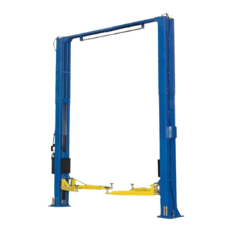
Atlas PV-12PX Installation & Operation Manual
12,000 lb. capacity two-post overhead lift
Hide thumbs
Also See for PV-12PX:
- Installation & operation manual (50 pages) ,
- Installation & operation manual (40 pages) ,
- Installation & operation manual (50 pages)
Table of Contents
Advertisement
Quick Links
Advertisement
Table of Contents

Related Manuals for Atlas PV-12PX


Summary of Contents for Atlas PV-12PX
- Page 1 Model: PV12 Revised: 09/29/23...
-
Page 2: Table Of Contents
CONTENTS Product Features and Specifications ...........3 Installation Requirement ..............5 Installation Steps ….................7 Exploded View ................32 Test Run ..................36 Operation Instruction ..............38 Maintenance ..................39 Trouble Shooting ................40 Warranty ..................41... -
Page 3: Product Features And Specifications
I. PRODUCT FEATURES AND SPECIFICATIONS CLEAR-FLOOR DIRECT-DRIVE MODEL FEATURES Model PV12 (See Fig. 1) · Direct-drive design minimizes the lift wear parts and breakdown ratio. · Dual hydraulic cylinders, designed and made to high standards, utilizing imported oil seal in cylinder. ·... - Page 4 Arm Swings View For Model PV12 Fig. 2...
-
Page 5: Installation Requirement
II. INSTALLATION REQUIREMENT A. TOOLS REQUIRED ✓ Rotary Hammer Drill (Φ19) Carpenter’s Chalk ✓ ✓ Hammer Screw Sets ✓ ✓ Level Bar Tape Measure (7.5m) ✓ ✓ English Spanner (12") Pliers ✓ ✓ Ratchet Spanner With Socket (28 Socket Head Wrench (3 ✓... - Page 6 B. Equipment storage and installation requirements. The equipment should be stored or installed in a shady, moderately temperate, ventilated and dry place. C. The equipment should be unloaded and transferred by forklift. Fig. 4 D. SPECIFICATIONS OF CONCRETE (See Fig. 5) Concrete specifications must be followed accordingly.
-
Page 7: Installation Steps
III. INSTALLATION STEPS A. Location of installation Check and ensure the installation location (concrete, layout, space size etc.) is suitable for lift installation. B. Use a carpenter’s chalk line to establish installation layout of baseplate. (See Fig. 6) Chalk Line Fig. - Page 8 3. Lift the upper column with a forklift or hoist and loosen the bolts on the upper package stand. Remove the upper column and take out the parts in the bottom column. (See Fig. 9) Fig. 9 4. Lift the lower column with a forklift or hoist, remove the package stand, then take off the lower column and remove the parts from the inner column (See Fig.
- Page 9 Parts box Fig. 12 6. Check the parts of the parts bag 1 according to parts bag list (See Fig. 13). Fig. 13 Check the parts of the parts bag 2 according to parts bag list (See Fig. 14). Fig. 14...
- Page 10 D. Install the hydraulic hose and lock release cable brackets on extension columns (See Fig. 15). Fig. 15...
- Page 11 E. Install hydraulic cylinder Wrap both ends of straight fittings with white Teflon tape, install straight fitting in each cylinder (See Fig. 16) The fitting of the cylinder toward the hole of the column Fig. 16...
- Page 12 F. Install columns Lay down the columns on the installation site parallel to each other. Position the power side column according to the installation site. This lift is designed with 2-section columns. Adjust lift height according to the ceiling height and connect the inner and extension columns.
- Page 13 2. When the ceiling height is over 165 3/8” but is less than 177 1/8”, connect the extension columns using the middle set of holes (See Fig. 18) Low Setting Fig. 18...
- Page 14 3. When the ceiling height is less than 165 3/8”, connect the extension columns using the top set of holes (See Fig. 19) NOTE: THIS SETTING REQUIRES THE ADDITIONAL PURCHASE OF SHORTER CABLES Special Low Setting Fig. 19...
- Page 15 G. Position the columns Position the columns so the base plates line up with a chalk line. Position the offside column parallel to the power side column at the approximate width of 122 5/8”. Install the overhead cross beam. Level and plumb the columns, shim where necessary. Drill 3/4”...
- Page 16 H. Install overhead top beam 1. With help of the hook of top beam, put one side of top beam on top of the extension column and connecting the top beam to extension column by bolts, tighten the bolts. (See Fig. 21) Hook on the extension columns Tighten the bolts...
- Page 17 2. Assemble overhead top beam: tighten the anchor bolts (See Fig. 22) Tighten the anchor bolts with ratchet with socket The anchor bolts should be Torqued to 125 Ft Lbs. or 150 N.m Fig. 22...
- Page 18 I. Installing the limit switch control bar and limit switch (See Fig. 23) Fig. 23...
- Page 19 J. Install safety device (See Fig. 24 & Fig. 25) Fig. 24 Power side safety device Fig. 25 Offside safety device...
- Page 20 K. Lift the carriages up manually and set on the 1 set of locks. (See Fig. 26). Fig. 26...
- Page 21 L. Install cables 1. High setting cable connection: suitable for ceiling height over 177 1/8”. 1.1 Remove carriages’ plastic cover, pass cable through from the bottom of the carriages and be pull through the openings of the carriages, then screw on/adjust the two cable nuts (See Fig.
- Page 22 1.2 Connecting cable for high setting (See Fig. 28) Cable 2 Cable 1 Cable 1 Fig. 28...
- Page 23 2. Low setting cable connection; suitable for ceiling heights between 165 3/8” to 177 1/8”. (See Fig. 29) Note : Cable should go inside of the carriage. Cable 2 Cable 1 Cable 2 Fig. 29...
- Page 24 3. Special low setting cable connection; suitable for ceiling height less than 165 3/8”. NOTE: This setting requires purchase of additional cables. (See Fig. 30) Fig. 30...
- Page 25 M. Install power unit (See Fig. 31) Fig. 31...
- Page 26 N. Install oil hose At high setting and low setting oil hose connection (See Fig. 32) Fig. 32...
- Page 27 O. Install safety cable. Install safety cable from offside safety device to power-side safety device, pass through the top beam (See Fig. 33) Fig. 33...
- Page 28 P. Install hose retainers on both columns (See Fig. 34). Fig. 34...
- Page 29 Q. Install lifting arms and adjust the arm locks 1. Install lifting arms (See Fig. 35) 2. Lower the carriages down to the lowest position, then use an 8mm allen wrench to loosen the socket bolt (See Fig. 36) 3. Adjust moon gear as direction of arrow (See Fig.
- Page 30 Remove the short “Pig Tail” wire connected to the AC contactor terminals. This wire was used to test the motor after production. ATLAS Single phase motor Please Note: This motor is powered by Alternating Current and the terminals on the AC contactor are not wire color specific. There are no positive or negative terminals.
- Page 31 Fig. 39...
-
Page 32: Exploded View
IV. EXPLODED VIEW Model PV12 Fig. 40... - Page 33 PV12 PARTS LIST Item Part # Description 217001B Power side Column 2/203 PU220VETL-12 Power unit 209003 Bolt 209033 Lock Washer 209005 QL4L-520-00 Power side Lock Cover QL4L-210-00 Main Cam Lock 217069 Bolt 206006 Washer 206023 Self-Locking Nut 420018 Self-Locking Nut 217013 Bolt 420045...
- Page 34 Item Part # Description 217047B Arm Pin 209039 Lock Washer 209022 Washer 206049 Moon Gear 217052C Lift Arm 206048 Allen Bolt 206032 C-Clip 217043 Limit Ring 206036 Roll Pin 217044 Arm Lock 217045 Spring 217046A Left Arm Lock Bar 217046 Right Arm Lock Bar 209019 Flat Head Screw...
- Page 35 Item Part # Description QL4L-200-04 Torsion Spring 217031 Cam Lock 217033 Self-Locking Nut 217032 Cable Lock Hold 217029 Small Pulley Bracket PV12-4003 Oil Hose 305720 90 Fitting for Power Unit PV12-4004 Oil Hose PV10-4021 Extended fitting for Cylinder 217191 Hose Clamp SW-001 Hydraulic T-Fitting 420029...
-
Page 36: Test Run
Fig. 42 4. Adjust the lowering speed (Only for ATLAS power unit) (Adjust with a load on the lift) (See Fig. 43) You can adjust the lowering speed of the lift if needed: Loosen the locking nut on the throttle valve, and then turn the throttle valve clockwise to decrease the lowering speed, or counterclockwise to increase the lowering speed. - Page 37 5. Test with load After finishing the above adjustment, test running the lift with load. Run the lift in low position several times first. Run the lift to the top completely. NOTE: If the lift vibrated on the way up with a load, lubricate all pulley shafts and wear blocks.
-
Page 38: Operation Instruction
VI. OPERATION INSTRUCTIONS Please read the safety tips carefully before operating the lift To lift vehicle 1. Keep the lift area clean and free of clutter; 2. Position lift arms to the lowest position, on floor; 3. Open or swing lift arms away from center of lift; 4. -
Page 39: Maintenance
VII. MAINTENANCE SCHEDULE Monthly: 1. Re-torque the anchor bolts to 85 Ft Lbs; Note: All anchor bolts should take full torque. If any of the bolts do not for any reason, DO NOT use the lift until the bolt has been replaced. 2. -
Page 40: Trouble Shooting
VIII. TROUBLE SHOOTING TROUBLE CAUSE REMEDY 1. Start button does not work 1. Replace Start button 2. Wiring connections are not in good 2.Repair all wiring connections Motor does not condition 3. Motor burned out 3. Repair or replace motor 4. -
Page 41: Warranty
X. WARRANTY: This item is warranted for five (5) years on structural components, two (2) years on hydraulic cylinders, and one (1) year on electric or air / hydraulic power units from invoice date. Wear items are covered by a 90 day warranty.
Need help?
Do you have a question about the PV-12PX and is the answer not in the manual?
Questions and answers