Table of Contents
Advertisement
Quick Links
Advertisement
Table of Contents

Related Manuals for Atlas pv-15p


Summary of Contents for Atlas pv-15p
-
Page 2: Table Of Contents
CONTENTS Product Features and Specifications ..........3 Installation Requirement ..............5 Steps of Installation ..............6 Exploded View ................32 Test Run ................... 35 Operation Instruction ..............37 Maintenance ................37 Trouble Shooting ................38 Parts List ..................39... -
Page 3: Product Features And Specifications
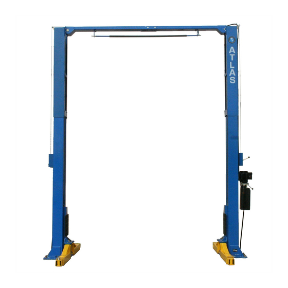
I. PRODUCT FEATURES AND SPECIFICATIONS CLEAR-FLOOR DIRECT-DRIVED MODEL FEATURES Model PV-15P (See Fig. 1) · Direct-drive design, minimizes the lift wear parts and breakdown ratio · Dual hydraulic cylinders, designed and made on ANSI standards, utilizing NOK oil seal in the cylinders ·... - Page 4 Arm Swings View For Model PV-15P 63 ¼” 41 1/8” 109 ¾” 41 1/8” 63 ¼” 150 ¾” Fig. 2 - 4 -...
-
Page 5: Installation Requirement
II. INSTALLATION REQUIREMENT A. TOOLS REQUIRED Rotary Hammer Drill (19mm / ¾”) Carpenter’s Chalk Hammer Screw Sets Level Tape Measure (25ft) Crescent Wrench (12") Pliers Lock Wrench Wrench set :(10 # # #... -
Page 6: Steps Of Installation
Check the installation location (concrete, layout, space size etc.) is suitable for lift installation. B. Use a carpenter’s chalk line to establish installation layout of the base plate (See Fig. 5) Model PV-15P Chalk Line 150 ¾” Fig. 5 - 6 -... -
Page 7: Move The Lift Aside With A Fork Lift Or Hoist, And Open The Outer Packing Carefully See Fig
C. Check the parts before assembly. 1. Packaged lift, hydraulic power unit and parts box ( See Fig. 6). Fig. 6 2. Move the lift aside with a fork lift or hoist, and open the outer packing carefully (See Fig. 7). Serial No. - Page 8 4. Lift the upper column with a fork lift or hoist, loosen the bolts on the upper package stand, take off the upper outer column, then take out the parts in the inner column (See Fig. 9). Fig. 9 5. Lift the lower column with a fork lift or hoist, take down the package stand, then take off the lower outer column, take out the parts in the inner column (See Fig.
- Page 9 7. Open the carton of parts and check the parts according to parts box list (See Fig. 12). Fig. 12 8. Check the parts in the part bag #1 according to parts bag list (See Fig. 13). Fig. 13 9. Check the parts in the parts bag #2 according to parts bag list (See Fig.
-
Page 10: See Fig.
D. Install parts on the extension columns (See Fig. 15). Fig. 15 - 10 -... - Page 11 E. Install hydraulic cylinders Connect the extended straight fitting and 90° fitting, and then install the cylinder inside the carriages (See Fig. 16) Off side column Power side column The direction of fitting Fig. 16 - 11 -...
-
Page 12: See Fig.
F. Install columns Lay down the two columns on the installation site parallel, position the power side column according to the actual installation site. Usually, it is suggested to install power side column on the front-right side from which vehicles are driven to the lift. This lift is designed with 2-Section columns. -
Page 13: See Fig.
2. When the ceiling height is between 4200mm (165 3/8”) to 4500mm (177 1/8”), connect the outer columns with the middle hole (See Fig.18) Fig. 18 Low setting - 13 -... -
Page 14: See Fig.
3. When the ceiling height is less than 4200mm (165 3/8”), connect the outer columns with the upper hole. For this height setting you will need to purchase the shorter cables (part#217063) (See Fig.19) Fig. 19 Special low setting - 14 -... - Page 15 G. Position columns (Do not drill anchor holes at this time) Position the power side column in its designated place. Place the off side column approximately 12 1/2” from the power side column. Install the overhead top beam. Once the overhead top beam is in place and secured, the anchor holes can be drilled. (See Fig.20 &...
- Page 16 H. Install overhead top beam 1. With help of the hook on the top beam, put one side of the top beam on top of the extension column and connect the top beam to the extension column with bolts, tighten the bolts. Then assemble the connecting bracket (See Fig.
- Page 17 2. Assemble overhead top beam, tighten the columns anchor bolts (See Fig. 22) Tighten Fig. 22 - 17 -...
- Page 18 I. Installing the limit switch control bar and limit switch (See Fig. 23). Loosen Screw on the Drive Rod for adjustment, Tighten the screw after adjustment Adjust Drive Rod on Limit Switch Limit Switch connected with cable NC: Normal contact Fig.
- Page 19 J. Install safety device (See Fig. 24 & Fig. 25 Fig. 24 Power side safety device Fig. 25 Off side safety device - 19 -...
- Page 20 K. Lift the carriages up by hand and lock them at the same level (See Fig. 26). Fig. 26 - 20 -...
- Page 21 L. Install cables 1. High setting cable connection. Suitable for ceiling height over 4500mm (177 1/8”). 1.1 Take off the carriages plastic cover, the cable passes through from the bottom of the carriages and is pulled out from the opening of the carriages, then screw the two cable nuts (See Fig.
- Page 22 1.2 Connecting cable for high setting (See Fig. 28) High setting Cable 2 Cable 1 Cable 2 Fig. 28 - 22 -...
- Page 23 2. Low setting cable connection. Suitable for ceiling height between 4200mm (165 3/8”) to 4500mm (177 1/8”) (See Fig. 29) Low Setting Cable 2 Cable 1 Cable 2 Fig. 29 - 23 -...
- Page 24 3. Special low setting cable connection. Suitable for ceiling heights less than 4200mm (165 3/8”) This setting needs the optional short cable. (See Fig. 30). Special low setting Cable 2 Cable 1 Cable 2 Fig. 30 - 24 -...
- Page 25 M. Install power unit (See Fig. 31) Fig. 31 - 25 -...
- Page 26 N. Install oil hose. 1. High setting and low setting oil hose connection (See Fig. 32) Limit switch wire Oil hose Oil hose and wire pass through the support bracket Oil hose passes through the wire tube on top beam Oil hose connected with T-fitting Oil hose connected...
- Page 27 O. Install the safety cable. Install safety cable from offside safety assembly to power side safety assy., pass through the top beam (See Fig. 33) Safety cable passes through the small pulley Safety cable bracket Install safety cable from offside safety assembly first Safety cable connected with the power side safety...
- Page 28 P. Install retainers (See Fig. 34). Install retainer to fix the oil hose. Car in direction Fig. 34 - 28 -...
- Page 29 Q. Install the lifting arms (See Fig. 35) Lower the carriages down to the lowest position. Then use the socket head wrench to loosen the bolt . Adjust the arm lock in the direction of the arrow (See Fig.36) (See .
- Page 30 Connect the power source on the data plate of Power Unit. Note: 1. For safety purposes, the power wiring must contact a sufficient ground. ATLAS single phase motor 1. Remove the line of connecting terminal 4# on the control button and L1 on the AC contactor (See Fig.
- Page 31 contactor marked L1, L2. b. Connect wire 12# on the limit switch with terminal L1 on the AC contactor; Connect wire 11# with terminal 4# on the control button. Limit switch wire Power wire Fig. 41 4. Connection wire (See Fig. 42) Fig.
-
Page 32: Exploded View
III. EXPLODED VIEW Model:PV-15P Fig. 43 - 32 -... - Page 33 Cylinders Fig. 44 ATLAS Manual power unit (Fig. 50) 220V/50HZ, Single Phase Fig. 45 - 33 -...
- Page 34 Illustration of the hydraulic valve for ATLAS hydraulic power unit a. PEAK manual power unit, 220V/50HZ, Single phase (See Fig. 51) Oil return port Protective ring Relief valve Release valve Handle Release Oil Outlet valve Throttle valve Check valve Fig. 46...
-
Page 35: Test Run
Ⅴ. TEST RUN 1. Adjust synchronizing cable (See Fig. 47) Use Spanner to hold the cable fitting. Meanwhile, Cable nut use ratchet spanner to tighten the cable nut. Make sure two cables have the same tension so the two carriages locks click at the same time. Fig. - Page 36 5. Test with load After finishing the above adjustment, test run the lift with a load. Run the lift in low position several times first, make sure the carriages raise and lower at the same time. The safety locks should lock and release at the same time. Test run the lift to the top. Fig.
-
Page 37: Operation Instruction
Ⅵ. OPERATION INSTRUCTIONS Please read the safety tips carefully before operating the lift To lift vehicle 1. Keep clean of site near the lift; 2. Position lift arms to the lowest position; 3. To shortest lift arms; 4. Open lift arms; 5. -
Page 38: Trouble Shooting
V. TROUBLE SHOOTING TROUBLE CAUSE REMEDY 1. Button does not work 1. Replace button 2. Wiring connections are not in good 2.Repair all wiring connections condition Motor does not 3. Motor burned out 3. Repair or replace motor 4. Height limit switch is damaged 4.Replace the limit switch 5. -
Page 39: Parts List
IX. PARTS LIST FOR MODEL PV-15P Item Part# Description Qty. Note 217001A Power side column 209002A Power unit 209003 Bolt 209034 Lock washer 217002 217003 Power side lock cover 217004 Main cam lock 217069 Bolt 206006 Washer 206023 Self locking nut... - Page 40 Item Part# Description Qty. Note 620065 Shim 680030 Rubber pad frame support 217036 Bottom pulley 217037 Bottom pin 209038 Bolt 217047A Arm pin 209039 Lock washer 209022 Washer 206049 Moon gear 217052B Lifting arm Allen bolt 206048 C-clip 206032 Limit ring 217043 Roll pin 206036...
- Page 41 Item Part# Description Qty. Note 217008 Main spring 217009 Main lock 217010 Bolt 217011 217012 Small spacer 217050 Main lock pin 217051 Screw 217066 Bolt 217030 Torsion spring 217031 Cam lock 217033 Self locking nut 217032 Cable lock hold Small pulley 217029 bracket 217057B...
- Page 42 Parts For Hydraulic Cylinder (See Fig. 49) 61-1 209069 O-Ring 61-2 209070 Bleeding Plug 61-3 201029 Support Ring 61-4 201030 Y-Ring 61-5 201031 O-Ring 61-6 217074A Piston 61-7 209075 O-Ring 61-8 217089 Piston rod 61-9 217077 Piston rod fitting 61-10 209078 Dust ring Item...
- Page 43 Parts For PEAK Manual Power Unit, 220V/50Hz, Single phase (See Fig. 50) 203-1 440014 Motor 203-2 440015 Start capacitor 203-2A 440016 Run capacitor 203-3 209112 AC contactor 203-4 440017 Allen bolt 203-5 440018 Motor fix frame 203-6 209083A Motor connecting shaft 203-7 440019 Valve body...
- Page 44 Parts For PEAK Manual Power Unit 380V/50Hz, Three phase (See Fig. 50) 203A-1 440028 Motor 203A-2 209112 AC contactor 203A-3 440017 Allen bolt 203A-4 440018 Motor fix frame 203A-5 209083A Motor connecting shaft 203A-6 440019 Valve body 203A-7 209085A Relief valve 203A-8 209113 Throttle valve...
Need help?
Do you have a question about the pv-15p and is the answer not in the manual?
Questions and answers