inVENTer iV twin Assembly Instruction Manual
Hide thumbs
Also See for iV twin:
- Installation and operating instructions manual (36 pages) ,
- Installation and operating instructions manual (21 pages)

Related Manuals for inVENTer iV twin


Summary of Contents for inVENTer iV twin
- Page 1 Assembly instruction for the ® inVENTer ventilation system iV twin Manufacturer ® Öko-Haustechnik inVENTer GmbH Ortsstraße 4a, D-07751 Löberschütz Phone: +49 (0)36427-21920, Fax: +49 (0)36427-219213 www.inventer.de, info@inventer.de Status: 05/2011...
-
Page 2: Table Of Contents
Assembly wall mounting sleeve (channel IV twin) ............. 5 Assembly of exterior hood 09 .................... 9 Finalization of the iV twin from the inside ................ 11 Assembling the heat storage tank, ventilator and electrical connection......11 ... -
Page 3: Assembly Instruction "General Part
The ventilation system can only be commissioned after finishing all building activities! Identification points of the device inVENTer twin, according to construction permit DIBt: Z-51.3-198 Manufacturer: Öko-Haustechnik inVENTer GmbH, Ortsstraße 4a, D-07751 Löberschütz Year of manufacture: 2011 Overview:... - Page 4 The iV twin was especially developed for individual room ventilation. The inVENTer ventilator may not be used in rooms that are subject to high levels of dust accumulation (e.g., in model construction) and may not be used in rooms with aggressive or corrosive gases.
- Page 5 The ventilators are allocated via the project, which must be checked and possibly changed after controller start-up. During the delivery state the ventilators are set to "exhaust". With correct installation, the iV twin ensures operation in pairs. Synchronisation:When utilising several ventilators activated by several controllers, synchronous collaboration must be observed.
-
Page 6: Assembly Wall Mounting Sleeve (Channel Iv Twin)
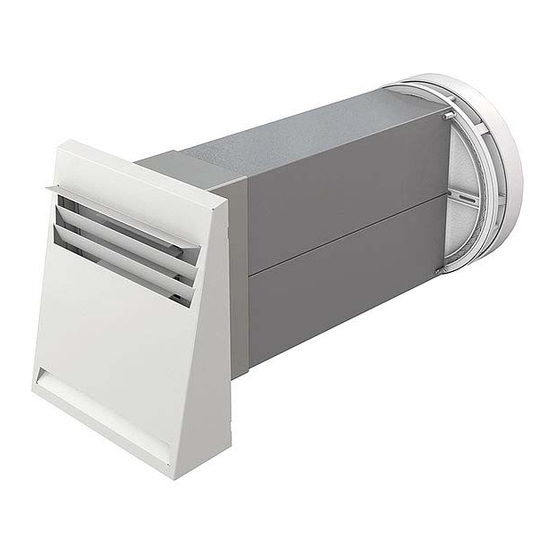
B: Inside C: Outside Included in delivery - Channel iV twin: 400 mm (Art. no. 1506-0004) / 550 mm (Art. no. 1506-0010) / 700 mm (Art. no. 1506-0011) / 900 mm (Art. no. 1506-0012) - Sliding sleeve - Assembly wedge... - Page 7 Assembly of wall mounting sleeve (channel IV twin) Specify the installation location, wall opening and cable installation Inside Minimum distance surrounding from the edge of the wall mounting sleeve to the wall/ceiling Later, there must be a space of at least...
- Page 8 Assembly of wall mounting sleeve (channel IV twin) The heat storage tank or suitable material must therefore be in the wall mounting sleeve during installation. The screws in the fastening elements of the wall mounting sleeve are removed only after finishing the wall mounting work (thread protection).
- Page 9 Assembly of wall mounting sleeve (channel IV twin) The distance between the wall mounting sleeve and the wall breakthrough (fill area [W]) must be about 10 mm. Secure the wall mounting sleeve using the enclosed assembly wedge inside and out.
-
Page 10: Assembly Of Exterior Hood 09
3. Assembly of exterior hood 09 3. Assembly of exterior hood 09 The exterior hood 09 is a component of the inVENTer ventilation system. It consists of a board and a stainless steel hood painted in "white" or brushed "plain". - Page 11 Thereafter, slide the exterior hood from the top onto the exterior plate. Close possible gaps between the exterior hood and plaster on top and at the sides using a permanent elastic sealant, which is also suitable for the outside. ® inVENTer www.inventer.de...
-
Page 12: Finalization Of The Iv Twin From The Inside
4. Finalization of the iV twin from the inside 4.1 Assembling the heat storage tank, ventilator and electrical connection The heat storage tank and ventilator are components of the inVENTer ventilation system. The heat storage tank consists of a ceramic block that is enclosed by a closed-pored insulating material. - Page 13 4. Finalization of the iV twin from the inside Electrical connection This description refers to utilizing the inVENTer round cable. Other cables (Braids!) must be connected correspondingly. For connecting the braids please use wire sleeves with flange avoid unwanted short circuits.
-
Page 14: Assembly Of The Inner Cover Plate
4. Finalization of the iV twin from the inside 4.2 Assembly of the inner cover plate The inner cover plate is a necessary component of the inVENTer ventilation system. It is closeable and only suitable for indoor spaces. Therefore, it may not be used outdoors. A dust filter is included in the delivery. - Page 15 The separating plate is slid horizontally into the centre, as shown below. In the open position, the cap is positioned in such a way that the word "inVENTer" can be read. In order to close the hood, this must be taken off and the separating plate removed. For storage, the separating plate is clamped to the inside of the cap, then the cap is turned 180°...
-
Page 16: Service And Maintenance
2.5 watts per ventilator (effective). The inner cover plate must be open at all times in order for the inVENTer to fully function. If the inVENTer is not in operation, then the inner cover plate should be closed. - Page 17 Slide the heat storage tank into the wall not moved outside mounting sleeve until it is against the stop strap. Additional noise Outside noise (street noise) can be reduced by insulation required using a noise insulation mat. ® inVENTer www.inventer.de...
- Page 18 Personal notes (e.g., responsible authorised dealer; invoice number / delivery note number):...
- Page 20 Öko-Haustechnik inVENTer GmbH Ortsstraße 4a D-07751 Löberschütz Phone: +49 (0)36427 – 2192 0 Fax: +49 (0)36427 – 2192 13 info@inventer.de www.inventer.de Subject to technical changes! Copyright: Öko-Haustechnik inVENTer GmbH, copyies are only permitted permission l-map-montage-iVtwin-110513-en...
Need help?
Do you have a question about the iV twin and is the answer not in the manual?
Questions and answers