Table of Contents
Advertisement
Quick Links
Advertisement
Table of Contents

Related Manuals for inVENTer iV-Office


Summary of Contents for inVENTer iV-Office
- Page 1 Installation and operating instructions...
- Page 2 GmbH. The copyright of this document remains with the manufacturer. Rights to all content and images: © inVENTer GmbH 2014 - 2 0. All trademarks used in this document are the property of their respective manufacturers and are hereby acknowledged.
-
Page 3: Table Of Contents
Attaching the inner cover panel ..................41 Specifications .......................... 42 General specifications ...................... 42 iV-Office energy label according to ErP Directive, Regulation 1254/2014 ....... 43 Specifications according to ErP Directive, Regulation 1254/2014 ........44 Scope of supply ........................46 Accessories and spare parts ....................47 10 Troubleshooting and disposal .................... - Page 4 Warranty and guarantee......................51 12 Service ............................51 13 Annex 1: Connection log ......................52 14 Annex 2: Cleaning log ......................53 iV-Office ventilation device • Installation and operating instructions...
-
Page 5: User And Safety Instructions
USER AND SAFETY INSTRUCTIONS User and safety instructions Thank you for purchasing this high quality product from inVENTer! This section provides an overview of the basic safety precautions for safe and proper operation of your ventilation unit. User information Safety instructions The safety and warning instructions in these installation and operating instructions have a uniform structure and are marked with a symbol on the left side of the instruction. -
Page 6: Safety Instructions
• Use the equipment/system exclusively for the applications that are described in this documentation and only in conjunction with components that are recommended, authorised and described by inVENTer GmbH in this documentation. Changes or modifications to the equipment/system are not permitted. - Page 7 Avoid contact with sharp or pointed objects, e.g. rings. • NOTE: Do not use strong cleaning agents or solvents. Use a soft, damp cloth to clean the plastic surfaces. iV-Office ventilation device • Installation and operating instructions...
- Page 8 The ventilation device complies with the technical safety requirements and standards of electrical appliances for domestic use. It conforms to current European Union directives: • 2014/30/EC: Electromagnetic compatibility • 2009/125/EC: Eco-design • 2014/35/EC: Low voltage • 2011/65/EC: RoHS iV-Office ventilation device • Installation and operating instructions...
-
Page 9: System Overview
SYSTEM OVERVIEW System overview The iV-Office is a decentralised ventilation unit with heat recovery and is designed for increased air flow requirements (performance-plus device). The iV-Office is suitable for installation in new buildings as well as for retrofitting in older buildings and is particularly suitable for use in large living spaces and similar commercial premises (e.g. -
Page 10: Construction
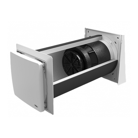
USER AND SAFETY INSTRUCTIONS Construction Flex weather protection hood Figure 1: Overview of iV-Office ventilation device Components Exterior closure: Thermal accumulator insert (thermal accumulator and inVENTron) Flex weather protection hood 1 Weather protection hood base plate 6 Sound insulation lining made... -
Page 11: Function
USER AND SAFETY INSTRUCTIONS Function The iV-Office ventilation unit is used to provide ventilation for living spaces and living space-like commercial premises. An integrated ceramic thermal accumulator ensures optimum heat recovery. The ventilation device operates on the principle of heat Supply mode recovery by changing the direction of the fan. -
Page 12: Control Elements
• Ventilation • Off (only sMove standard version) MZ-Home controller The MZ-Home controller is an electronic programming unit for controlling up to eight iV-Office ventilation devices. It features Clust-Air technology (multi-zone control), easy installation, touch operation and a wide variety of possible uses. -
Page 13: Preparing For Installation
Flex Office weather protection hood: 450 mm from borehole centre/centre axis 3 to adjoining components on the interior wall: 250 mm from borehole centre/centre axis 4 to frontally adjacent components: 300 mm for cleaning work iV-Office ventilation device • Installation and operating instructions... -
Page 14: Position Of The Wall Opening
Position of the wall opening With Flex weather protection hood: ≥ 250 Ø Figure 2: Dimensional drawing of the iV-Office wall opening (interior view) 1 Wall opening (Fig. 2, left) 3 Reveal Simplex wall installation system (Fig. 2, right) 4 Door/window frame... -
Page 15: Sectional Drawing Of The Ventilation Device
PREPARING FOR INSTALLATION Sectional drawing of the ventilation device 1 – 2° Wall thickness ≥ 260 Figure 3: Sectional drawing of the iV-Office ventilation device with Flex weather protection hood A Plaster / interior structure C Insulation B Masonry D Render... -
Page 16: Dimensional Drawings Of Components
1 Weather protection hood base plate 4 Protective grid 2 Fixing borehole exterior wall Ø 8 mm, 5 Drip rail min. 50 mm deep (4 x) 6 Flex Office insert (pre-assembled) 3 Weather protection hood cover iV-Office ventilation device • Installation and operating instructions... - Page 17 Figure 5: Dimensional drawing of the Flair - XL V-280x280 inner cover white SDE 1 Inner cover panel 2 SDE sound insulation insert 3 Inner cover base plate 4 Spacer (4 x) 5 Interior wall fixing borehole 6 Flair XL adapter 7 Fan bus entry iV-Office ventilation device • Installation and operating instructions...
-
Page 18: Installation And Assembly
Check the scope of supply Check the delivery for completeness and transport damage upon receipt using the delivery note. Report missing items immediately. Figure 6: iV-Office ventilation device standard components 1 Exterior closure 3 iV-Office thermal accumulator insert 1 a: Flex Office weather protection... -
Page 19: Create Wall Opening
► Drill a wall opening, Ø 270 mm with a slope of 1° to 2° to the exterior wall. 1 – 2° The wall opening for the ventilation device has been created. iV-Office ventilation device • Installation and operating instructions... -
Page 20: Installing The Fan Bus
Only connect the cable to the control unit when it is de-energised. Instructions for installing the fan BUS (including maximum cable lengths) can be found in the installation and operating instructions supplied with the controller. iV-Office ventilation device • Installation and operating instructions... - Page 21 ► Re-plaster the plaster/masonry slot. Ensure that the cable end protrudes approx. 500 mm (min. wall thickness X, section 4.4) into the interior. The fan BUS is installed. iV-Office ventilation device • Installation and operating instructions...
-
Page 22: Installing The Wall Sleeve
Ensure that the cut-out for the fan BUS is on the interior wall side and near the plaster/masonry slot. ► Guide the fan BUS through the cut-out in the wall sleeve. iV-Office ventilation device • Installation and operating instructions... - Page 23 ► Align the two lateral fastening elements of the wall sleeve horizontally. ► Insert the protective discs into the wall sleeve from the inside and outside. iV-Office ventilation device • Installation and operating instructions...
- Page 24 Take care not to damage the fan BUS. ► If necessary, trim the wall sleeve so it is flush with the render. ► Deburr the edges. The wall sleeve is installed. iV-Office ventilation device • Installation and operating instructions...
-
Page 25: Installing The Ventilation Device's Exterior Closure
► Level the base plate using a spirit level. ► Mark the four boreholes: Outer boreholes (blue arrow): Masonry. ø 8 mm ► Create the four boreholes with Ø 8 mm, min. 50 mm deep. iV-Office ventilation device • Installation and operating instructions... - Page 26 ► Seal the joint between the cover and the exterior wall at the sides and top with a permanently elastic exterior sealant. The Flex Office weather protection hood is installed. iV-Office ventilation device • Installation and operating instructions...
-
Page 27: Inserting The Thermal Accumulator Insert
► Shorten the sound insulation lining with a cutter so it is flush with the interior wall. Take care not to damage the fan BUS. The sound insulation lining is inserted. iV-Office ventilation device • Installation and operating instructions... - Page 28 BUS plug connection. Make sure that the narrow Slim guiding vane [16 mm] is directed towards the interior. The thermal accumulator insert has been inserted. iV-Office ventilation device • Installation and operating instructions...
-
Page 29: Installing The Inner Cover Base Plate
► Align the base plate with the inner cover adapter using a spirit level. ► Mark the four corner drill holes. ø = 6 mm ► Drill the four holes with Ø 6 mm, min. 40 mm deep. iV-Office ventilation device • Installation and operating instructions... - Page 30 ► Screw the base plate into the rawl plugs with the screws. Make sure that the marking arrow on the base plate is pointing upwards. The inner cover base plate is fitted. iV-Office ventilation device • Installation and operating instructions...
-
Page 31: Connect The Reversible Fan To The Controller And Check Its Function
► Set ventilation operating mode (DL) on the connected controller. (see the controller's installation and operating instructions) ► Make sure that all reversible fans rotate in the same direction. The functional test has been performed. iV-Office ventilation device • Installation and operating instructions... -
Page 32: Starting Ventilation Unit
Colour Colour block block block III (–) GND (–) White CW (–) Blue CCW (–) Black IV (+) Operating voltage Green V (–) GND (–) Brown CCW (–) Black CW (–) Blue iV-Office ventilation device • Installation and operating instructions... -
Page 33: Installing The Inner Cover Panel
► Place the panel on the four spacers. Ensure that the position arrows on the back of the panel are pointing upwards. Check: The inVENTer logo is located at the bottom right. ► Press the detent lugs inwards on the spacers. -
Page 34: Operation
Tilting the inner cover To reduce noise and direct the air flow, the Flair iV-Office inner cover panel can be tilted up or down. The inner cover is closed on the tilted side and the air flow is directed in the open direction. -
Page 35: Cleaning And Maintenance
The iV-Office ventilation unit is virtually maintenance free. Any necessary cleaning or care work can be carried out by the user after brief instructions. -
Page 36: Remove The Inner Cover Panel
► Pull the inner cover panel forwards. CLICK Ensure that all the spacers disengage. ► Remove the inner cover panel from the front. You have removed the panel of the inner cover. iV-Office ventilation device • Installation and operating instructions... -
Page 37: Cleaning / Replacing The Dust Filter
The tab on the filter ring faces the interior. ► Replace the cover on the four spacers. Make sure that the inVENTer logo is located at the bottom right-hand corner. ► Press the detent lugs inwards on the spacers. -
Page 38: Removing The Thermal Accumulator Insert
► Step 1: Remove the inVENTron insert from the wall sleeve by using the knob. ► Step 2: Remove the thermal accumulator from the wall sleeve by the handle. You have removed the thermal accumulator. iV-Office ventilation device • Installation and operating instructions... -
Page 39: Cleaning And Installing The Thermal Accumulator Insert
Step 2: Lift the guiding vane upwards. ► Turn the fan so that the remaining guiding vane is pointing upwards. ► Remove the guiding vane as described previously. The guiding vanes are separated from the fan. iV-Office ventilation device • Installation and operating instructions... - Page 40 Make sure that the narrow Slim guiding vane is facing the interior. ► Slide the inVENTron as far as the thermal accumulator. You have cleaned the thermal accumulator insert. iV-Office ventilation device • Installation and operating instructions...
-
Page 41: Attaching The Inner Cover Panel
The tab on the filter ring faces the interior. ► Replace the cover on the four spacers. Make sure that the inVENTer logo is located at the bottom right-hand corner. ► Press the detent lugs inwards on the spacers. -
Page 42: Specifications
(DIN EN 13141-8) Electrical protection area (in accordance with Outside protection areas 0 – 2 VDE 0100) Automatic by reversing operation Frost protection (down to -20 °C) Weight [g] Max. 8000 Conformity iV-Office ventilation device • Installation and operating instructions... -
Page 43: Iv-Office Energy Label According To Erp Directive, Regulation 1254/2014
Demand-controlled Manually controlled iV-Office MZ-Home sMove without sensor sMove with sensor technology technology 90 m dB (A) ENERGIA · ЕНЕРГИЯ · ΕΝΕΡΓΕΙΑ · ENERGIJA · ENERGY · ENERGIE · ENERGI 2020 1254/2014 iV-Office ventilation device • Installation and operating instructions... -
Page 44: Specifications According To Erp Directive, Regulation 1254/2014
SPECIFICATIONS Specifications according to ErP Directive, Regulation 1254/2014 iV-Office ventilation unit, demand-controlled: Product data sheet inVENTer GmbH (according to Regulation 1254/2014 EU of July 11, 2014) Description Parameters Supplier´s name inVENTer GmbH Supplier’s model identifier iV-Office cold -88,481 SEC class / Specific energy average -44,234 consumption (SEV) [kWh/(m²a)] -18,886... - Page 45 SPECIFICATIONS iV-Office ventilation device, manually controlled: Product data sheet inVENTer GmbH (according to Regulation 1254/2014 EU of July 11, 2014) Description Parameters Supplier´s name inVENTer GmbH Supplier’s model identifier iV-Office cold -82.817 SEC class / Specific energy average -39.977 consumption (SEV) [kWh/(m²a)] -15.435 Typology...
-
Page 46: Scope Of Supply
Wall sleeve with protective discs and mounting wedges Wall sleeve R-D250x495 1506-0072 Wall sleeve R-D250x745 1506-0073 Thermal accumulator insert WSP iV-Office insert incl. Inventin 495 1507-0028 WSP iV-Office insert incl. Inventin 745 1507-0029 Inner cover Flair-XL V-280x280 inner cover white SDE... -
Page 47: Accessories And Spare Parts
Slim R-D160 guiding vane incl. knob 3006-0278 inVENTron R-D200 guiding vane 3006-0393 Inventin cutout R-D250x495mm 2002-0084 Inventin cutout R-D250x745mm 2002-0085 R-D250 Office wall sleeve ring insert 2002-0088 Base plate IB Flair V-233x233 2003-0223 iV-Office ventilation device • Installation and operating instructions... - Page 48 Cover WSH-Flex, white – RAL 9016 2004-0202 Cover WSH-Flex, grey – RAL 9006 2004-0203 Cover WSH-Flex, north – RAL 7011 2004-0204 Cover WSH-Flex, anthracite – RAL7016 2004-0210 Cover WSH-Flex, custom colour 2004-0205 iV-Office ventilation device • Installation and operating instructions...
-
Page 49: Troubleshooting And Disposal
Check the connector plug on the Supply air is cold controller. The connector must be sitting firmly in the connector housing. The controller is operating Select heat recovery mode in Ventilation mode. on the controller. iV-Office ventilation device • Installation and operating instructions... - Page 50 Flair-XL V-280x280 inner PS-SZ Recyclable material cover white SDE Thermal accumulator Ceramic Domestic waste G4 dust filter TPU/PES Domestic waste Pollen filter Domestic waste Polyester fleece with Activated carbon filter Domestic waste activated carbon iV-Office ventilation device • Installation and operating instructions...
-
Page 51: Warranty And Guarantee
Manufacturer guarantee inVENTer GmbH provides a five-year warranty for all electrical components and the wall sleeve, as well as a 30-year warranty on the ceramic component of the thermal accumulator. This covers premature product wear. -
Page 52: Annex 1: Connection Log
ANNEX 1: CONNECTION LOG Annex 1: Connection log Starting direction Ventilation Floor Room name and position Ventilation zone Supply Extract device iV-Office ventilation device • Installation and operating instructions... -
Page 53: Annex 2: Cleaning Log
Inner cover / Filter if necessary (depending on filter type) Ceramic thermal accumulator, Xenion EFP reversible fan, Clean double guiding vane, wall sleeve, sound insulation lining Accessories Check, clean or replace if necessary iV-Office ventilation device • Installation and operating instructions... - Page 54 CEO: ANNETT WETTIG VAT ID NUMBER: DE 815494982 JENA DISTRICT COURT HRB 510380 ALL RIGHTS RESERVED / PICTURE CREDITS: © INVENTER GMBH 2020 SUBJECT TO MODIFICATIONS. ALL INFORMATION IS SUPPLIED WITHOUT GUARANTEE. NO LIABILITY IS ACCEPTED FOR PRINTING ERRORS. iV-Office ventilation device •...
- Page 55 GmbH Ortsstraße 4a 07751 Löberschütz Germany +49 (0) 36427 211-0 +49 (0) 36427 211-113 info@inventer.de Version 09/2020 Subject to modifications. Article number 5001-0030 www.inventer.de © inVENTer GmbH 2020...
Need help?
Do you have a question about the iV-Office and is the answer not in the manual?
Questions and answers