inVENTer iV-Light Installation Instructions Manual
Hide thumbs
Also See for iV-Light:
- Operating instructions manual (36 pages) ,
- Maintenance manual (2 pages) ,
- Manual (2 pages)
Table of Contents
Advertisement
Quick Links
Advertisement
Table of Contents

Related Manuals for inVENTer iV-Light


Summary of Contents for inVENTer iV-Light
- Page 1 Installation instructions iV-Light www.inventer.de...
- Page 2 ® inVENTer GmbH. The copyright to this document remains with the manufacturer. Rights to all content and images: © inVENTer GmbH 2021. All trademarks used in this document are the property of their respective manufacturers and are hereby acknowledged. Disclaimer This documentation represents an translation the original installation instructions.
-
Page 3: Table Of Contents
TABLE OF CONTENTS Table of contents User and safety instructions ....................4 User information ....................... 4 Safety instructions ......................5 System overview: iV-Light ventilation unit ................8 Construction ........................9 Function ........................... 10 Control elements ......................11 Preparing for installation ......................12 Installation position ...................... -
Page 4: User And Safety Instructions
USER AND SAFETY INSTRUCTIONS User and safety instructions Thank you for purchasing this high quality product from inVENTer! This section provides an overview of the basic safety precautions for safe and proper operation of your ventilation unit. User information Safety and warning instructions The safety and warning instructions in these installation instructions have a uniform structure and are marked with a symbol on the left side of the instruction. -
Page 5: Safety Instructions
These installation instructions only cover the standard variant (referred to as the "Standard vari- ant" in the following text) of the iV-Light ventilation unit. Information on the variants can be found in the separate installation instructions for the respective components. - Page 6 You should connect all controllers via a mains fuse in the house distribution board. If your unit has a fault, contact your nearest distributor or our technical service. Any kind of use other than the intended use will exclude all liability claims. iV-Light ventilation unit | Installation instructions...
- Page 7 The ventilation unit complies with the technical safety requirements and standards of electrical appliances for domestic use. It conforms to current European Union directives and United Kingdom standards: • 2014/30/EC: Electromagnetic compatibility • 2014/35/EC: Low voltage • 2009/125/EC: Eco-design • 2011/65/EC: RoHS iV-Light ventilation unit | Installation instructions...
-
Page 8: System Overview: Iv-Light Ventilation Unit
• Standard variant: iV-Light ventilation units with weather protection grille. The operating instructions for the controller are not part of this documentation. In connection with the inVENTer Connect controller platform, it is mandatory to use the Connect inner cover. iV-Light ventilation unit | Installation instructions... -
Page 9: Construction
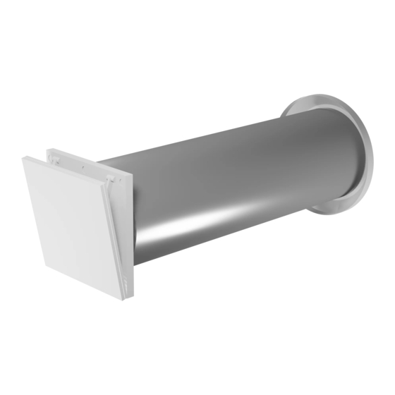
SYSTEM OVERVIEW: IV-LIGHT VENTILATION UNIT Construction Figure 1: Overview of the iV-Light ventilation unit Components External termination: Thermal accumulator insert Light weather protection grille (thermal accumulator and inVENTron) Weather protection grille Thermal accumulator with insulation Fixing claws (2 x, pre-installed) -
Page 10: Function
For this principle to work correctly and to ensure pressure stability in the room, the supply air vol- ume must always correspond to the extract air volume, i.e. at least two iV-Light ventilation devices are required. These are operated in pairs in push-pull mode: another ventilation unit is assigned to the ventilation unit that delivers supply air and at the same time removes used extract air from the interior to the outside. -
Page 11: Control Elements
SYSTEM OVERVIEW: IV-LIGHT VENTILATION UNIT Control elements The ventilation unit is operated via an inVENTer system controller. Depending on the controller, different operating modes and functions can be set. inVENTer Connect Designation sMove MZ-Home (Easy Connect e16) Number of controll- Max. -
Page 12: Preparing For Installation
1,2 m – 0,75 y 1,2 m 1,2 m Installation over corner 1,0 m 1,0 m 1,0 m 1,4 m 1,0 m 1,4 m 1,2 m – 0,75 y 1,2 m – 0,75 y iV-Light ventilation unit | Installation instructions... -
Page 13: Position Of The Wall Opening
Ø Position of wall opening Position of Simplex wall installation system Figure 2: Dimensioned drawing of the iV-Light wall opening (interior view) 1 Wall opening (Fig. 2, left) 2 Outer edge of reveal (insulation with Simplex wall installation system (Fig. 2, right) -
Page 14: Sectional Drawings Of The Ventilation Unit
For sectional drawings of other variants of your ventilation unit, see the installation instructions for your specific external termination. Sectional drawing of the iV-Light ventilation unit 1 – 2° ≥ 290 Figure 3: Sectional drawing of the iV-Light ventilation unit A Interior plaster/ interior structure C Insulation B Masonry D Render... -
Page 15: Dimensional Drawings Of Components
Figure 5: Dimensional drawing of Light V-220x220 inner cover 1 Inner cover base plate 5 Filter holder 2 Connecting element 6 Interior wall fixing hole (optional) 3 Locking hook 7 Connecting element fixing 4 Inner cover panel iV-Light ventilation unit | Installation instructions... -
Page 16: Installation And Assembly
For the scope of supply of the external terminations variants, wall sleeves for integrating the Connect controller platform and the interior closure variants, please refer to the separately available installation instructions for the respective system component. Figure 6: iV-Light ventilation unit standard components 1 External termination: 3 iV-Light thermal accumulator insert... -
Page 17: Create Wall Opening
► Create an opening for the flush-mounted housing on the interior wall, centred on the core drill hole,for installing the inner cover. Dimensions: 245 x 245 x 40 (W x H x D, mm) iV-Light ventilation unit | Installation instructions... -
Page 18: Laying The Cables To The Wall Opening Of The Ventilation Unit
NYM-J 3x1.5 mm² cover) RS485 data cable, Unit communication Easy Connect e16 operating unit e. g.: (only if the system compo- Type J-Y(ST)Y 2x2x0.8 mm² nents communicate by cable [otherwise radio]) iV-Light ventilation unit | Installation instructions... - Page 19 Length max. 500 m System communication by radio: Cable NYM-J, wire cross-section 1.5 mm² House distributor Operating unit: Control unit: Control unit: Easy Connect e16 Connect inner cover Connect inner cover Ventilation unit n Ventilation unit 1 iV-Light ventilation unit | Installation instructions...
-
Page 20: Installing The Wall Sleeve
A + B + C + D - 38 ► Cut the wall sleeve to the determined dimension X + a protrusion of Y on the exterior wall. Be careful not to cut away the cut-out for the ventilation unit connecting cable. iV-Light ventilation unit | Installation instructions... - Page 21 • Before foaming the free space between the wall sleeve and masonry, insert styrofoam discs. ► Insert the styrofoam discs into the wall sleeve from the inside and outside. iV-Light ventilation unit | Installation instructions...
- Page 22 Flush with the exterior wall Flush with the exterior wall • • 30 mm 30 mm 30 mm Take care not to damage the connecting cable on the interior wall. The wall sleeve is installed. iV-Light ventilation unit | Installation instructions...
-
Page 23: Installing The Ventilation Unit's External Terminal
Both ends of the end-stop tape are located above the horizontal central axis, so that the fixing claws on the weather protection grille are able to hook into the wall sleeve on the left and right. iV-Light ventilation unit | Installation instructions... - Page 24 The fixing claws hook into the wall sleeve. ► Seal the joint between the panel and the exterior wall all the way around with a permanently elastic exterior sealant. (2) The weather protection grille is installed. iV-Light ventilation unit | Installation instructions...
-
Page 25: Inserting The Thermal Accumulator Insert
► Insert the inVENTron from the interior into the Standard wall sleeve so that you can reach the BUS plug Slim connection. The narrow Slim guiding vane [16 mm] is aligned towards the interior. The thermal accumulator insert has been inserted. iV-Light ventilation unit | Installation instructions... -
Page 26: Electrical Connection Of The Reversible Fan
Electrical connection of the reversible fan The function of the iV-Light ventilation system requires the simultaneous operation of two iV-Light ventilation units in push-pull mode. This section therefore describes the connection of a pair of units, not a single unit. - Page 27 ► Reconnect the connected plug-in connector to the plug-in connector on the reversible fan. a Ventilation unit with start direction extract air mode b Ventilation unit with start direction supply air mode The reversible fan is connected to the controller. iV-Light ventilation unit | Installation instructions...
-
Page 28: Check Function And Complete Fan Installation
► Set heat recovery operating mode (WRG) on the connected controller. (see the controller's installation and operating instructions) ► Push the connected and checked fan as far as the thermal accumulator. inVENTron is connected and installed. iV-Light ventilation unit | Installation instructions... -
Page 29: Installing The Inner Cover
• The thermal accumulator insert has been installed. ► Slide the pre-assembled inner cover into the wall sleeve. The inVENTer logo is located at the bottom right. ► Level the inner cover base plate using a spirit level. TIP: If the inner cover does not sit firmly enough in the wall sleeve, it can optionally be screwed onto the interior wall. -
Page 30: Technical Data
Sensitivity of the air flow at ± 20 Pa (EN 13141-8) Electrical protection area Outside protection areas 0 – 2 (in accordance with VDE 0100) Automatic by reversing operation Frost protection (down to -20 °C) Conformity iV-Light ventilation unit | Installation instructions... -
Page 31: Iv- Light Energy Label According To Erp Directive, Regulation 1254/2014
On the energy label you will find the following information from the product data sheet: • Energy efficiency class (SEC class) • Sound power level L • Maximum air flow (supply air) Demand-controlled Manually controlled MZ-Home sMove without sensor sMove with sensors technology Easy Connect e16 iV-Light ventilation unit | Installation instructions... -
Page 32: Specifications According To Erp Directive, Regulation 1254/2014
TECHNICAL DATA Specifications according to ErP Directive, Regulation 1254/2014 iV-Light ventilation unit, demand-controlled: iV-Light product data sheet according to EU Ordinance 1254/2014 dated 11 July 2014 Description Values Supplier inVENTer GmbH Model identifier iV-Light Cold -85.671 SEC class / Specific Energy Average -42.513... - Page 33 TECHNICAL DATA iV-Light ventilation unit, manually controlled: iV-Light product data sheet according to EU Ordinance 1254/2014 dated 11 July 2014 Description Values Supplier inVENTer GmbH Model identifier iV-Light Cold -78.012 SEC class / Specific Energy Average -36.847 Consumption (SEC) [kWh/(m²a)] Warm -13.265...
-
Page 34: Scope Of Supply
In connection with the Connect controller platform, the inner cover is not part of the scope of delivery. The Connect inner cover is ordered as part of the Connect controller platform and replaces the Light or Undercover manual inner cover. iV-Light ventilation unit | Installation instructions... -
Page 35: Troubleshooting And Disposal
Check the connector plug on the Supply air is cold controller. The connector plug must be sitting firmly in the connector housing. The controller is operating in Select heat recovery mode on the ventilation mode. controller. iV-Light ventilation unit | Installation instructions... -
Page 36: Warranty And Guarantee
Manufacturer guarantee inVENTer GmbH provides a five-year warranty for all electrical components and the wall sleeve, as well as a 30-year warranty on the ceramic component of the thermal accumulator. This covers premature product wear. - Page 37 WARRANTY AND GUARANTEE NOTES iV-Light ventilation unit | Installation instructions...
- Page 38 WARRANTY AND GUARANTEE NOTES iV-Light ventilation unit | Installation instructions...
- Page 39 WARRANTY AND GUARANTEE NOTES iV-Light ventilation unit | Installation instructions...
- Page 40 GmbH Ortsstraße 4a D-07751 Löberschütz Germany www.inventer.eu Subject to modifications. We accept no liability for printing errors. Item number: 5001-0042 Version: 1.0 – 07/2021...
Need help?
Do you have a question about the iV-Light and is the answer not in the manual?
Questions and answers