inVENTer iV-Office Installation Instructions Manual
Hide thumbs
Also See for iV-Office:
- Installation and operating instructions manual (55 pages) ,
- Cleaning (2 pages)
Table of Contents
Advertisement
Quick Links
Advertisement
Table of Contents

Related Manuals for inVENTer iV-Office


Summary of Contents for inVENTer iV-Office
- Page 1 Installation instructions iV-Office www.inventer.de...
- Page 2 ® inVENTer GmbH. The copyright to this document remains with the manufacturer. Rights to all content and images: © inVENTer GmbH 2021. All trademarks used in this document are the property of their respective manufacturers and are hereby acknowledged. Disclaimer This documentation represents an translation of the original installation instructions.
-
Page 3: Table Of Contents
Installing the inner cover panel ..................32 Technical data .......................... 33 General specifications ....................33 iV-Office energy label according to ErP Directive, Regulation 1254/2014 ..... 34 Specifications according to ErP Directive, Regulation 1254/2014 ......... 35 Scope of supply ........................37 Troubleshooting ........................ -
Page 4: User And Safety Instructions
USER AND SAFETY INSTRUCTIONS User and safety instructions Thank you for purchasing this high quality product from inVENTer! This section provides an overview of the basic safety precautions for safe and proper operation of your ventilation unit. User information Safety and warning instructions The safety and warning instructions in these installation instructions have a uniform structure and are marked with a symbol on the left side of the instruction. -
Page 5: Safety Instructions
USER AND SAFETY INSTRUCTIONS Safety instructions The installation instructions are part of your iV-Office ventilation unit and must be available at all times (see www.inventer.de/downloads). When handing the system to a third party, the informa- tion regarding access to the installation instructions must be handed over also. - Page 6 You should connect all controllers via a mains fuse in the house distribution board. If your unit has a fault, contact your nearest distributor or our technical service. Any kind of use other than the intended use will exclude all liability claims. iV-Office ventilation unit | Installation instructions...
- Page 7 The ventilation unit complies with the technical safety requirements and standards of electrical appliances for domestic use. It conforms to current European Union directives and United Kingdom standards:: • 2014/30/EC: Electromagnetic compatibility • 2014/35/EC: Low voltage • 2009/125/EC: Eco-design • 2011/65/EC: RoHS iV-Office ventilation unit | Installation instructions...
-
Page 8: System Overview: Iv-Office Ventilation Unit
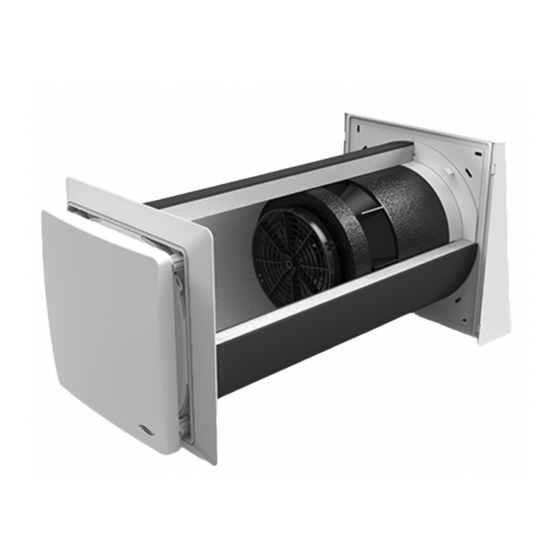
The ventilation unit consists of a wall sleeve in which the thermal accumulator insert is mounted. A lockable inner cover conceals the iV-Office discreetly from the interior. The filter integrated into the inner cover ensures that no pollen or dust from outside enters the interior. Outside, a driving rain-proof cover conceals the components of the ventilation unit. -
Page 9: Construction
SYSTEM OVERVIEW: IV-OFFICE VENTILATION UNIT Construction Standard variant Flex Office Figure 1: Overview of the iV-Office ventilation unit Components External termination: Thermal accumulator insert Flex Office weather protection hood (Thermal accumulator, inVENTron, sound insulation lining made of Inventin) 1 Weather protection hood base plate... -
Page 10: Function
For this principle to work correctly and to ensure pressure stability in the room, the supply air volume must always correspond to the extract air volume, i. e. at least two iV-Office ventilation units are required. These are operated in pairs in push-pull mode: another ventilation unit is assigned to the ventilation unit that delivers supply air and at the same time removes used extract air from the interior to the outside. -
Page 11: Control Elements
SYSTEM OVERVIEW: IV-OFFICE VENTILATION UNIT Control elements The ventilation unit is operated via an inVENTer system controller. Depending on the controller, different operating modes and functions can be set. Designation sMove MZ-Home Number of controllable Max. 4 Max. 8 (excl. sensors) -
Page 12: Preparing For Installation
1,2 m – 0,75 y 1,2 m 1,2 m Installation over corner 1,0 m 1,0 m 1,4 m 1,0 m 1,0 m 1,4 m 1,2 m – 0,75 y 1,2 m – 0,75 y iV-Office ventilation unit | Installation instructions... -
Page 13: Position Of The Wall Opening
≥ 250 Ø Position of wall opening Position of Simplex wall sleeve system Figure 2: Dimensional drawing of the iV-Office wall opening (interior view) 1 Wall opening (Fig. 2, left) 3 Reveal Simplex wall installation system (Fig. 2, right) 4 Door/window frame... -
Page 14: Sectional Drawing Of The Ventilation Unit
Sectional drawing of the ventilation unit For sectional drawings of other variants of your ventilation unit, see the installation instructions for your specific external termination. Sectional drawing of the iV-Office ventilation unit, standard variant 1 – 2° Wandstärke ≥ 260... -
Page 15: Dimensional Drawings Of Components
Figure 5: Dimensional drawing of the Flair XL V-280x280 inner cover incl. SDE 1 Inner cover panel 5 Interior wall fixing borehole 2 SDE sound insulation insert 6 Inner cover base plate 3 Flair XL adapter 7 Pass-through for controller connecting 4 Spacer (4 x) cable iV-Office ventilation unit | Installation instructions... -
Page 16: Installation And Assembly
The Flex-Office weather protection hood is available in different colours and materials (stainless steel / aluminium [with increased salt resistance]) and must be ordered according to the desired colour and properties. Figure 6: iV-Office ventilation unit standard components 1 External termination 3 iV-Office thermal accumulator insert... -
Page 17: Create Wall Opening
1° to 2° to the exterior wall. 1 – 2° ► Drill a wall opening, Ø 270 mm with a slope of 1° to 2° to the exterior wall. The wall opening for the ventilation unit has been created. iV-Office ventilation unit | Installation instructions... -
Page 18: Laying The Cables To The Wall Opening Of The Ventilation Unit
Cable type Cable origin sMove Operating voltage fan Stranded cable sMove operating unit and unit 6 – 16 V DC, MZ-Home Clust-Air module CAM17 communication e. g.: LiYY 3x0.75 mm² in the ventilation zone iV-Office ventilation unit | Installation instructions... - Page 19 MZ-Home: Clust-Air module Cable type LiYY, 3-wire, Star-shaped: Ventilation wire cross-section 0.75 mm², length max. 33 m units Operated in pairs Control unit: Terminal Switching power sMove: Control unit blocks supply unit MZ-Home: Clust-Air module iV-Office ventilation unit | Installation instructions...
-
Page 20: Installing The Wall Sleeve
The recess for the connecting cables is located on the interior wall side and near the cables laid to the wall opening. ► Guide all connecting cables through the cut-out in the wall sleeve. iV-Office ventilation unit | Installation instructions... - Page 21 Take care not to damage the connecting cable on the interior wall. ► If necessary, trim the wall sleeve so it is flush with the render. ► Deburr the edges. The wall sleeve is installed. iV-Office ventilation unit | Installation instructions...
-
Page 22: Installing The Ventilation Unit's External Termination
► Level the base plate using a spirit level. ► Mark the four drill holes (blue arrow). ø 8 mm ► Drill the four holes with Ø 8 mm, min. 50 mm deep. iV-Office ventilation unit | Installation instructions... - Page 23 ► Place the cover onto the base plate from the top. ► Slide the cover downwards as far as the stop. The guides on the cover hook in behind the base plate. The Flex Office weather protection hood is installed. iV-Office ventilation unit | Installation instructions...
-
Page 24: Inserting The Thermal Accumulator Insert
(approx. 12 o'clock). ► Make sure that the sound insulation lining made of Inventin is pushed into the ring insert on the weath- er protection hood. iV-Office ventilation unit | Installation instructions... - Page 25 ► Shorten the sound insulation lining on the inner wall side with a cutter so it is flush with the wall sleeve. Take care not to damage the connecting cable on the interior wall. The sound insulation lining is inserted. iV-Office ventilation unit | Installation instructions...
- Page 26 ► Insert the inVENTron from the interior into the wall sleeve so that you can reach the BUS plug connection. The narrow Slim guiding vane [16 mm] is aligned towards the interior. The thermal accumulator insert has been inserted. iV-Office ventilation unit | Installation instructions...
-
Page 27: Installing The Inner Cover Base Plate
► Clip the adapter into the base plate so that • The position arrow on the base plate is pointing upwards, and • The positions of the cable entry and connecting cable match. The inner cover base plate is prepared. iV-Office ventilation unit | Installation instructions... - Page 28 ► Screw the base plate into the rawl plugs with the screws. The position arrow on the base plate points upwards. The inner cover base plate is fitted. iV-Office ventilation unit | Installation instructions...
-
Page 29: Electrical Connection Of The Reversible Fan
Electrical connection of the reversible fan The function of the iV-Office ventilation system requires the simultaneous operation of two iV-Office ventilation units in push-pull mode. This section therefore describes the connection of a pair of units, not a single unit. - Page 30 ► Reconnect the connected plug-in connector to the plug-in connector on the reversible fan. a Ventilation unit with start direction extract air mode b Ventilation unit with start direction supply air mode The reversible fan is connected to the controller. iV-Office ventilation unit | Installation instructions...
-
Page 31: Check Function And Complete Fan Installation
► Set heat recovery operating mode (WRG) on the connected controller. (see the controller's installation and operating instructions) ► Push the connected and checked fan as far as the thermal accumulator. inVENTron is connected and installed. iV-Office ventilation unit | Installation instructions... -
Page 32: Installing The Inner Cover Panel
► Place the panel on the four spacers. The position arrows on the back of the inner cover panel point upwards. Check: The inVENTer logo is located at the bottom right 4 x CLICK ► Press the locking lugs inwards on the spacers. -
Page 33: Technical Data
Sensitivity of the air flow at ± 20 Pa (EN 13141-8) Electrical protection area Outside protection areas 0 – 2 (in accordance with VDE 0100) Automatic by reversing operation Frost protection (down to -20 °C) Conformity iV-Office ventilation unit | Installation instructions... -
Page 34: Iv-Office Energy Label According To Erp Directive, Regulation 1254/2014
TECHNICAL DATA iV-Office energy label according to ErP Directive, Regulation 1254/2014 On the energy label you will find the following information from the product data sheet: • Energy efficiency class (SEC class) • Sound power level L • Maximum air flow (supply air) -
Page 35: Specifications According To Erp Directive, Regulation 1254/2014
TECHNICAL DATA Specifications according to ErP Directive, Regulation 1254/2014 iV-Office ventilation unit, demand-controlled: iV-Office product data sheet according to EU Ordinance 1254/2014 dated 11 July 2014 Description Values Supplier inVENTer GmbH Model identifier iV-Office Cold -88.481 SEC class / Specific Energy Average -44.234... - Page 36 TECHNICAL DATA iV-Office ventilation unit, manually controlled: iV-Office product data sheet according to EU Ordinance 1254/2014 dated 11 July 2014 Description Values Supplier inVENTer GmbH Model identifier iV-Office Cold -82.817 SEC class / Specific Energy Con- Average -39.977 sumption (SEC) [kWh/(m²a)] Warm -15.435...
-
Page 37: Scope Of Supply
Wall sleeve with styrofoam discs and mounting wedges Wall sleeve R-D250x495 1506-0072 Wall sleeve R-D250x745 1506-0073 Thermal accumulator insert iV-Office thermal accumulator insert [incl. Inventin 495 mm] 1507-0028 iV-Office thermal accumulator insert [incl. Inventin 745 mm] 1507-0029 Inner cover Flair XL V-280x280 inner cover, white, incl. SDE... -
Page 38: Troubleshooting
Check the connector plug on the control- Supply air is cold ler. The connector plug must be sitting firmly in the connector housing. The controller is operating in Select heat recovery mode on the ventilation mode. controller. iV-Office ventilation unit | Installation instructions... -
Page 39: Warranty And Guarantee
Manufacturer guarantee inVENTer GmbH provides a five-year guarantee for all electrical components and the wall sleeve, as well as a thirty-year guarantee on the ceramic component of the thermal accumulator. This covers premature product wear. - Page 40 GmbH Ortsstraße 4a D-07751 Löberschütz Germany www.inventer.eu Subject to modifications. We accept no liability for printing errors. Item number: 5001-0043 Version: 1.0 – 07/2021...
Need help?
Do you have a question about the iV-Office and is the answer not in the manual?
Questions and answers