inVENTer iV14-Zero Installation Instructions Manual
Hide thumbs
Also See for iV14-Zero:
- User and safety instructions (52 pages) ,
- Operating instructions manual (36 pages) ,
- Installation instructions manual (36 pages)
Table of Contents
Advertisement
Quick Links
Advertisement
Table of Contents

Related Manuals for inVENTer iV14-Zero


Summary of Contents for inVENTer iV14-Zero
- Page 1 Installation instructions iV14-Zero www.inventer.de...
- Page 2 ® inVENTer GmbH. The copyright to this document remains with the manufacturer. Rights to all content and images: © inVENTer GmbH 2021. All trademarks used in this document are the property of their respective manufacturers and are hereby acknowledged. Disclaimer This documentation represents an translation of the original installation instructions.
-
Page 3: Table Of Contents
Installing the inner cover panel ..................33 Technical data .......................... 34 General specifications ....................34 iV14-Zero energy label according to ErP Directive, Regulation 1254/2014 ....35 Specifications according to ErP Directive, Regulation 1254/2014 ......... 36 Scope of supply ........................38 Troubleshooting ........................ -
Page 4: User And Safety Instructions
USER AND SAFETY INSTRUCTIONS User and safety instructions Thank you for purchasing this high quality product from inVENTer! This section provides an overview of the basic safety precautions for safe and proper operation of your ventilation unit. User information Safety and warning instructions The safety and warning instructions in these installation instructions have a uniform structure and are marked with a symbol on the left side of the instruction. -
Page 5: Safety Instructions
USER AND SAFETY INSTRUCTIONS Safety instructions The installation instructions are part of your iV14-Zero ventilation unit and must be available at all times (see www.inventer.de/downloads). When handing the system to a third party, the informa- tion regarding access to the installation instructions must be handed over also. - Page 6 You should connect all controllers via a mains fuse in the house distribution board. If your unit has a fault, contact your nearest distributor or our technical service. Any kind of use other than the intended use will exclude all liability claims. iV14-Zero ventilation unit | Installation instructions...
- Page 7 The ventilation unit complies with the technical safety requirements and standards of electrical appliances for domestic use. It conforms to current European Union directives and United Kingdom standards: • 2014/30/EC: Electromagnetic compatibility • 2014/35/EC: Low voltage • 2009/125/EC: Eco-design • 2011/65/EC: RoHS iV14-Zero ventilation unit | Installation instructions...
-
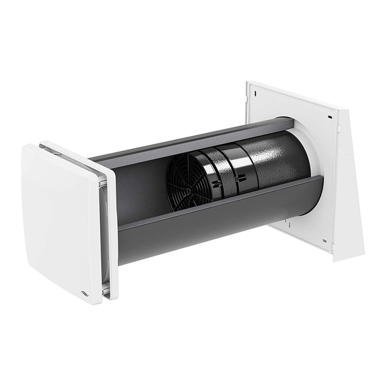
Page 8: System Overview: Iv14-Zero Ventilation Unit
The ventilation unit consists of a wall sleeve in which the thermal accumulator insert is mounted. A closeable inner cover with integrated air filter seals the iV14-Zero off from the interior space. Outside, a driving rain-proof cover conceals the components of the ventilation unit. -
Page 9: Construction
SYSTEM OVERVIEW: IV14-ZERO VENTILATION UNIT Construction Standard variant Flex Zero Figure 1: Overview of the iV14-Zero standard variant ventilation unit Components External termination: Thermal accumulator insert Flex Zero weather protection hood (Thermal accumulator, inVENTron, sound insulation lining made of Inventin) -
Page 10: Function
For this principle to work correctly and to ensure pressure stability in the room, the supply air volume must always correspond to the extract air volume, i.e. at least two iV14-Zero ventilation units are required. These are operated in pairs in push-pull mode: another ventilation unit is as- signed to the ventilation unit that delivers supply air and at the same time removes used extract air from the interior to the outside. -
Page 11: Control Elements
SYSTEM OVERVIEW: IV14-ZERO VENTILATION UNIT Control elements The ventilation unit is operated via an inVENTer system controller. Depending on the controller, different operating modes and functions can be set. inVENTer Connect Designation sMove MZ-Home (Easy Connect e16) Number of controll- Max. -
Page 12: Preparing For Installation
1,2 m – 0,75 y 1,2 m 1,2 m Installation over corner 1,0 m 1,0 m 1,0 m 1,0 m 1,4 m 1,4 m 1,2 m – 0,75 y 1,2 m – 0,75 y iV14-Zero ventilation unit | Installation instructions... -
Page 13: Position Of The Wall Opening
≥ 250 Ø Position of wall opening Position of Simplex wall sleeve system Figure 2: Dimensional drawing of the iV14-Zero wall opening (interior view) 1 Wall opening (Fig. 2, left) 3 Reveal Simplex wall installation system (Fig. 2, right) 4 Door/window frame... -
Page 14: Sectional Drawings Of The Ventilation Unit
Sectional drawing of the ventilation unit For sectional drawings of other variants of your ventilation unit, see the installation instructions for your specific external termination. Sectional drawing of the iV14-Zero ventilation unit, standard variant 1 – 2° ≥ 255 Figure 3: Sectional drawing of the iV14-Zero ventilation unit... -
Page 15: Dimensional Drawings Of Components
5 Guide for sealing tape 2 Flex Zero ring insert (pre-installed) 6 Weather protection hood cover 3 Exterior wall fixing hole (4 x) 7 Protective grid 4 Simplex fixing hole (4 x) 8 Drip rail iV14-Zero ventilation unit | Installation instructions... -
Page 16: Installation And Assembly
The Flex-Zero weather protection hood is available in different colours and materials (stainless steel / aluminium [with increased salt resistance]) and must be ordered according to the desired colour and properties. Figure 6: iV14-Zero ventilation unit standard components 1 External termination 3 iV14-Zero thermal accumulator insert... -
Page 17: Create Wall Opening
► Create an opening for the flush-mounted housing on the interior wall, centred on the core drill hole, for installing the inner cover. Dimensions: 245 x 245 x 40 (W x H x D, mm) iV14-Zero ventilation unit | Installation instructions... -
Page 18: Laying The Cables To The Wall Opening Of The Ventilation Unit
NYM-J 3x1.5 mm² cover) RS485 data cable, Unit communication Easy Connect e16 operating unit e. g.: (only if the system compo- Type J-Y(ST)Y 2x2x0.8 mm² nents communicate by cable [otherwise radio]) iV14-Zero ventilation unit | Installation instructions... - Page 19 The corresponding connection diagrams and assembly steps for installing the controller are not part of this documentation! They can be found in the installation instructions for the respective control unit. (sMove, MZ-Home, inVENTer Connect controller platform). 6 – 16 V DC...
-
Page 20: Installing The Wall Sleeve
(min. 30 mm) ► Cut the wall sleeve to the determined dimension X + a protrusion of Y on the exterior wall. Be careful not to cut away the cut-out for the fan connecting cable. iV14-Zero ventilation unit | Installation instructions... - Page 21 • Do not remove the thread locks of the fixing elements until the inner cover is attached. ► Align the two lateral fastening elements of the wall sleeve horizontally. iV14-Zero ventilation unit | Installation instructions...
- Page 22 Flush with the exterior wall Flush with the exterior wall • • 30 mm 30 mm 30 mm Take care not to damage the connecting cable on the interior wall. The wall sleeve is installed. iV14-Zero ventilation unit | Installation instructions...
-
Page 23: Installing The External Termination Of The Standard Ventilation Unit Variant
► Level the base plate using a spirit level. ► Mark the four boreholes: Outer boreholes (blue arrow): Masonry. ø 8 mm Inner boreholes (green arrow): Simplex. ► Drill the four holes with Ø 8 mm, min. 50 mm deep. iV14-Zero ventilation unit | Installation instructions... - Page 24 ► Place the cover onto the base plate from the top. ► Slide the cover downwards as far as the stop. The guides on the cover hook in behind the base plate. The Flex Zero weather protection hood is installed. iV14-Zero ventilation unit | Installation instructions...
-
Page 25: Inserting The Thermal Accumulator Insert
(any ring insert present is aligned with the exterior wall). Position the abutting surfaces (red arrow) in the upper section of the wall sleeve (ap- prox. 12 o'clock [upper fastening element]). iV14-Zero ventilation unit | Installation instructions... - Page 26 ► Shorten the sound insulation lining on the inner wall side with a cutter so it is flush with the wall sleeve. Take care not to damage the connecting cable on the interior wall. The sound insulation lining is inserted. iV14-Zero ventilation unit | Installation instructions...
- Page 27 ► Insert the inVENTron from the interior into the wall sleeve so that you can reach the BUS plug Standard connection. The narrow Slim guiding vane [16 mm] Slim is aligned towards the interior. The thermal accumulator insert has been inserted. iV14-Zero ventilation unit | Installation instructions...
-
Page 28: Installing The Inner Cover Base Plate
► Clip the Flair Zero insert into the base plate so that • The position arrow on the base plate is pointing upwards, and • The positions of the cable entry and connecting cable match. The inner cover base plate is prepared. iV14-Zero ventilation unit | Installation instructions... - Page 29 ► Screw the base plate to the wall sleeve's fixing elements using a hex key. The position arrow on the base plate points upwards. The inner cover base plate is fitted. iV14-Zero ventilation unit | Installation instructions...
-
Page 30: Electrical Connection Of The Reversible Fan
Electrical connection of the reversible fan The function of the iV-Zero ventilation system requires the simultaneous operation of two iV14-Zero ventilation units in push-pull mode. This section therefore describes the connection of a pair of units, not a single unit. - Page 31 ► Reconnect the connected plug-in connector to the plug-in connector on the reversible fan. a Ventilation unit with start direction extract air mode b Ventilation unit with start direction supply air mode The reversible fan is connected to the controller. iV14-Zero ventilation unit | Installation instructions...
-
Page 32: Check Function And Complete Fan Installation
► Set heat recovery operating mode (WRG) on the connected controller. (see the controller's installation and operating instructions) ► Push the connected and checked fan as far as the thermal accumulator. inVENTron is connected and installed. iV14-Zero ventilation unit | Installation instructions... -
Page 33: Installing The Inner Cover Panel
► Place the panel on the four spacers. The position arrows on the back of the inner cover panel point upwards. Check: The inVENTer logo is located at the 4 x CLICK bottom right. ► Press the locking lugs inwards on the spacers. -
Page 34: Technical Data
Sensitivity of the air flow at ± 20 Pa (EN 13141-8) Electrical protection area Outside protection areas 0 – 2 (in accordance with VDE 0100) Automatic by reversing operation Frost protection (down to -20 °C) Conformity iV14-Zero ventilation unit | Installation instructions... -
Page 35: Iv14-Zero Energy Label According To Erp Directive, Regulation 1254/2014
TECHNICAL DATA iV14-Zero energy label according to ErP Directive, Regulation 1254/2014 On the energy label you will find the following information from the product data sheet: • Energy efficiency class (SEC class) • Sound power level L • Maximum air flow (supply air) -
Page 36: Specifications According To Erp Directive, Regulation 1254/2014
TECHNICAL DATA Specifications according to ErP Directive, Regulation 1254/2014 iV14-Zero ventilation unit, demand-controlled: iV14-Zero product data sheet according to EU Ordinance 1254/2014 dated 11 July 2014 Description Values Supplier inVENTer GmbH iV14-Zero Model identifier iV14-Zero Corner iV14-Zero Nordic Cold -88.068... - Page 37 TECHNICAL DATA iV14-Zero ventilation unit, manually controlled: iV14-Zero product data sheet according to EU Ordinance 1254/2014 dated 11 July 2014 Description Values Supplier inVENTer GmbH iV14-Zero Model identifier iV14-Zero Corner iV14-Zero Nordic Cold -82.062 SEC class / Specific Energy Con- Average -39.422...
-
Page 38: Scope Of Supply
Wall sleeve with Styrofoam discs and mounting wedges Wall sleeve R-D200x495 1506-0070 Wall sleeve R-D200x745 1506-0071 Thermal accumulator insert iV14-Zero thermal accumulator insert [incl. Inventin 495 mm] 1507-0018 iV14-Zero thermal accumulator insert [incl. Inventin 745 mm] 1507-0019 iV14-Zero Corner/Nordic thermal accumulator insert 1507-0025 [incl. -
Page 39: Troubleshooting
Check the connector plug on the control- Supply air is cold ler. The connector plug must be sitting firmly in the connector housing. The controller is operating in Select heat recovery mode on the ventilation mode. controller. iV14-Zero ventilation unit | Installation instructions... -
Page 40: Warranty And Guarantee
Manufacturer guarantee inVENTer GmbH provides a five-year warranty for all electrical components and the wall sleeve, as well as a 30-year warranty on the ceramic component of the thermal accumulator. This covers premature product wear. - Page 41 WARRANTY AND GUARANTEE NOTES iV14-Zero ventilation unit | Installation instructions...
- Page 42 WARRANTY AND GUARANTEE NOTES iV14-Zero ventilation unit | Installation instructions...
- Page 43 WARRANTY AND GUARANTEE NOTES iV14-Zero ventilation unit | Installation instructions...
- Page 44 GmbH Ortsstraße 4a D-07751 Löberschütz Germany www.inventer.eu Subject to modifications. We accept no liability for printing errors. Item number: 5001-0040 Version: 1.1 – 07/2021...
Need help?
Do you have a question about the iV14-Zero and is the answer not in the manual?
Questions and answers