inVENTer iV14-MaxAir Installation And Operating Instructions Manual
Hide thumbs
Also See for iV14-MaxAir:
- Installation instructions manual (36 pages) ,
- Cleaning (2 pages)
Table of Contents
Advertisement
Quick Links
Advertisement
Table of Contents

Related Manuals for inVENTer iV14-MaxAir


Summary of Contents for inVENTer iV14-MaxAir
- Page 1 Installation and operating instructions...
- Page 2 GmbH. The copyright of this document remains with the manufacturer. Rights to all content and images: © inVENTer GmbH 2014-20. All trademarks used in this document are the property of their respective manufacturers and are hereby acknowledged.
-
Page 3: Table Of Contents
Attaching the inner cover panel ..................39 Specifications .......................... 40 General specifications ...................... 40 IV14-MaxAir energy label according to ErP Directive, Regulation 1254/2014 ....41 Specifications according to ErP Directive, Regulation 1254/2014 ........42 Scope of supply ........................44 Accessories and spare parts ....................45 10 Troubleshooting and disposal .................... - Page 4 Warranty and guarantee......................49 12 Service ............................49 13 Annex 1: Connection log ......................50 14 Annex 1: Connection log ......................51 15 Annex 2: Cleaning log ......................52 Ventilation device iV14-MaxAir • Installation and operating instructions...
-
Page 5: User And Safety Instructions
USER AND SAFETY INSTRUCTIONS User and safety instructions Thank you for purchasing this high quality product from inVENTer! This section provides an overview of the basic safety precautions for safe and proper operation of your ventilation unit. User information Safety instructions The safety and warning instructions in these installation and operating instructions have a uniform structure and are marked with a symbol on the left side of the instruction. -
Page 6: Safety Instructions
• Use the equipment/system exclusively for the applications that are described in this documentation and only in conjunction with components that are recommended, authorised and described by inVENTer GmbH in this documentation. Changes or modifications to the equipment/system are not permitted. - Page 7 Avoid contact with sharp or pointed objects, e.g. rings. • NOTE: Do not use strong cleaning agents or solvents. Use a soft, damp cloth to clean the plastic surfaces. Ventilation device iV14-MaxAir • Installation and operating instructions...
- Page 8 The ventilation device complies with the technical safety requirements and standards of electrical appliances for domestic use. It conforms to current European Union directives: • 2014/30/EC: Electromagnetic compatibility • 2009/125/EC: Eco-design • 2014/35/EC: Low voltage • 2011/65/EC: RoHS Ventilation device iV14-MaxAir • Installation and operating instructions...
-
Page 9: System Overview
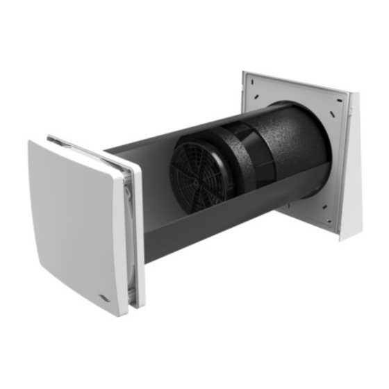
The ventilation device consists of a wall sleeve in which the thermal accumulator insert is mounted. A lockable inner cover conceals the iV14-MaxAir discreetly from the interior. The filter integrated into the inner cover ensures that no pollen or dust from outside enters the interior. -
Page 10: Construction
USER AND SAFETY INSTRUCTIONS Construction Flex weather protection hood Figure 1: Overview of the iV14-MaxAir ventilation device Components Exterior closure: Thermal accumulator insert (thermal accumulator and inVENTron) Flex weather protection hood 1 Weather protection hood base plate 5 Thermal accumulator with insulation... -
Page 11: Function
USER AND SAFETY INSTRUCTIONS Function The iV14-MaxAir ventilation unit is used to provide ventilation for living spaces and living space-like commercial premises. An integrated ceramic thermal accumulator ensures optimum heat recovery. The ventilation device operates on the principle of heat Supply mode recovery by changing the direction of the fan. -
Page 12: Control Elements
• Ventilation • Off (only sMove standard version) MZ-Home controller The MZ-Home controller is an electronic programming unit for controlling up to eight iV14-MaxAir ventilation devices. It features Clust-Air technology (multi-zone control), easy installation, touch operation and a wide variety of possible uses. -
Page 13: Preparing For Installation
Flex weather protection hood: 450 mm from borehole centre/centre axis 3 to adjoining components on the interior wall: 250 mm from borehole centre/centre axis 4 to frontally adjacent components: 300 mm for cleaning work Ventilation device iV14-MaxAir • Installation and operating instructions... -
Page 14: Position Of The Wall Opening
≥ 250 Ø Position of wall opening Position of Simplex wall installation system Figure 2: Dimensioned drawing of the iV14-MaxAir wall opening (interior view) 1 Wall opening (Fig. 2, left) 3 Reveal Simplex wall installation system (Fig. 2, right) 4 Door/window frame... -
Page 15: Sectional Drawing Of The Iv14-Maxair Ventilation Device
PREPARING FOR INSTALLATION Sectional drawing of the iV14-MaxAir ventilation device 1 – 2° Wall thickness ≥ 280 Figure 3: Sectional drawing of the iV14-MaxAir ventilation device with Flex weather protection hood A Plaster / interior structure C Insulation B Masonry... -
Page 16: Dimensional Drawings Of Components
Minimum distance to adjacent components on the interior wall Attach the weather protection hood at lintel height Ensure a minimum distance to adjoining building components Note insulation thickness and any roller shutters on the exterior wall Ventilation device iV14-MaxAir • Installation and operating instructions... - Page 17 1 Inner cover panel 2 SDE sound insulation insert 3 Holding plate 4 Inner cover base plate 5 Spacer (4 x) 6 Fixing borehole interior wall, Ø 6 mm, 40 mm deep (4 x) Ventilation device iV14-MaxAir • Installation and operating instructions...
-
Page 18: Installation And Assembly
Check the scope of supply Check the delivery for completeness and transport damage upon receipt using the delivery note. Report missing items immediately. Figure 6: Standard components of the iV14-MaxAir ventilation device 1 Exterior closure 3 c: Xenion EFP reversible fan... -
Page 19: Create Wall Opening
► Drill a wall opening, Ø 225 mm with a slope of 1° to 2° to the exterior wall. 1 – 2° The wall opening for the ventilation device has been created. Ventilation device iV14-MaxAir • Installation and operating instructions... -
Page 20: Installing The Fan Bus
Switching power Control unit Ventilation devices supply unit Cable type LiYY, 3-wire, max 33 m Star-shaped: Operated in pairs Ventilation devices Terminal Switching power Control unit Operated in pairs blocks supply unit Ventilation device iV14-MaxAir • Installation and operating instructions... - Page 21 ► Re-plaster the plaster/masonry slot. Ensure that the cable end protrudes approximately 500 mm into the interior space. The fan BUS is installed. Ventilation device iV14-MaxAir • Installation and operating instructions...
-
Page 22: Installing The Wall Sleeve
► Note the thickness of the plaster. Ensure that the cut-out for the fan BUS is on the interior wall side and near the plaster/masonry slot. ► Guide the fan BUS through the cut-out in the wall sleeve. Ventilation device iV14-MaxAir • Installation and operating instructions... - Page 23 ► Trim the 2K polyurethane foam and protruding mounting wedges so they are flush with the exterior and interior wall. Take care not to damage the fan BUS. The wall sleeve is installed. Ventilation device iV14-MaxAir • Installation and operating instructions...
-
Page 24: Installing The Ventilation Device's Exterior Closure
Make sure that the cut-out in the circumferential end-stop tape is placed in the lower area of the wall sleeve. ► Break the pre-punched ring out of the base plate. Ventilation device iV14-MaxAir • Installation and operating instructions... - Page 25 These are not included in the scope of supply, they are available as an option. Ventilation device iV14-MaxAir • Installation and operating instructions...
- Page 26 ► Seal the joint between the cover and the exterior wall at the sides and top with a permanently elastic exterior sealant. The Flex weather protection hood is installed. Ventilation device iV14-MaxAir • Installation and operating instructions...
-
Page 27: Inserting The Thermal Accumulator Insert
Make sure that the narrow Slim guiding vane [16 mm] is directed towards the interior. The thermal accumulator insert has been inserted. Ventilation device iV14-MaxAir • Installation and operating instructions... -
Page 28: Connect The Reversible Fan To The Controller And Check Its Function
► Set ventilation operating mode (DL) on the connected controller. (see the controller's installation and operating instructions) ► Make sure that all reversible fans rotate in the same direction. The functional test has been performed. Ventilation device iV14-MaxAir • Installation and operating instructions... -
Page 29: Starting Ventilation Unit
Colour Colour block block block III (–) GND (–) White CW (–) Blue CCW (–) Black IV (+) Operating voltage Green V (–) GND (–) Brown CCW (–) Black CW (–) Blue Ventilation device iV14-MaxAir • Installation and operating instructions... -
Page 30: Installing The Inner Cover
The thermal accumulator insert has been installed. The start direction of the reversible fan is set. ► Break out the four tabs on the inner cover base plate with pliers at the predetermined breaking points. Ventilation device iV14-MaxAir • Installation and operating instructions... - Page 31 Ensure you push the detent lugs on the spac- ers inwards. ► Slide the inner cover panel onto the spacers. All spacers noticeably snap in. The Flair V-233x233 inner cover is installed. Ventilation device iV14-MaxAir • Installation and operating instructions...
-
Page 32: Operation
The inner cover panel is tilted downwards (upwards). The flow rate will be directed upwards (downwards). The sound pressure level is reduced. Ventilation device iV14-MaxAir • Installation and operating instructions... -
Page 33: Cleaning And Maintenance
The iV14-MaxAir ventilation unit is virtually maintenance free. Any necessary cleaning or care work can be carried out by the user after brief instructions. -
Page 34: Remove The Inner Cover Panel
► Pull the inner cover panel forwards. Ensure that all the spacers disengage. ► Remove the inner cover panel from the front. You have removed the panel of the inner cover. Ventilation device iV14-MaxAir • Installation and operating instructions... -
Page 35: Cleaning / Replacing The Dust Filter
The tab on the filter ring faces the interior. ► Replace the cover on the four spacers. Make sure that the inVENTer logo is located at the bottom right-hand corner. ► Press the detent lugs inwards on the spacers. -
Page 36: Removing The Thermal Accumulator Insert
► Step 1: Remove the inVENTron insert from the wall sleeve by using the knob. ► Step 2: Remove the thermal accumulator from the wall sleeve by the handle. You have removed the thermal accumulator. Ventilation device iV14-MaxAir • Installation and operating instructions... -
Page 37: Cleaning And Installing The Thermal Accumulator Insert
Step 2: Lift the guiding vane upwards. ► Turn the fan so that the remaining guiding vane is pointing upwards. ► Remove the guiding vane as described previously. The guiding vanes are separated from the fan. Ventilation device iV14-MaxAir • Installation and operating instructions... - Page 38 Make sure that the narrow Slim guiding vane is facing the interior. ► Reassemble the plug connection. ► Slide the inVENTron as far as the thermal accumulator. You have cleaned the thermal accumulator insert. Ventilation device iV14-MaxAir • Installation and operating instructions...
-
Page 39: Attaching The Inner Cover Panel
The tab on the filter ring faces the interior. ► Replace the cover on the four spacers. Make sure that the inVENTer logo is located at the bottom right-hand corner. ► Press the detent lugs inwards on the spacers. -
Page 40: Specifications
Sensitivity of the air flow at ± 20 Pa (DIN EN 13141-8) S2 Electrical protection area (in accordance with Outside protection areas 0 – 2 VDE 0100) Automatic by reversing operation Frost protection (down to -20 °C) Weight Max. 7000 Conformity Ventilation device iV14-MaxAir • Installation and operating instructions... -
Page 41: Iv14-Maxair Energy Label According To Erp Directive, Regulation 1254/2014
SPECIFICATIONS IV14-MaxAir energy label according to ErP Directive, Regulation 1254/2014 On the energy label you will find the following information from the product data sheet: • Energy efficiency class (SEC class) • Sound power level L • Maximum air flow (supply air) -
Page 42: Specifications According To Erp Directive, Regulation 1254/2014
SPECIFICATIONS Specifications according to ErP Directive, Regulation 1254/2014 iV14-MaxAir ventilation unit, demand-controlled: Product data sheet inVENTer GmbH (according to Regulation 1254/2014 EU of July 11, 2014) Description Parameters Supplier´s name inVENTer GmbH Supplier’s model identifier iV14-MaxAir cold -88,481 SEC class / Specific energy average -44,234 consumption (SEV) [kWh/(m²a)]... - Page 43 SPECIFICATIONS iV14-MaxAir ventilation device, manually controlled: Product data sheet inVENTer GmbH (according to Regulation 1254/2014 EU of July 11, 2014) Description Parameters Supplier´s name inVENTer GmbH Supplier’s model identifier iV14-MaxAir cold -82.817 SEC class / Specific energy average -39.977 consumption (SEV) [kWh/(m²a)] -15.435...
-
Page 44: Scope Of Supply
Wall sleeve with protective discs and mounting wedges Wall sleeve R-D200x495 1506-0070 Wall sleeve R-D200x745 1506-0071 Thermal accumulator insert iV14-MaxAir thermal accumulator insert 1507-0030 Inner cover Inner cover Flair V-223x223, white 1505-0036 Flair V-223x233 inner cover, white, incl. SDE 1505-0037 Ventilation device iV14-MaxAir •... -
Page 45: Accessories And Spare Parts
1506-0090 Simplex 490 incl. R-D200 wall sleeve 1506-0091 D230 V-280x249x120 wall installation block 3008-0078 R-D230x30 protective disc (for wall installation block) 3007-0106 WEH R-D200 extension set 1004-0176 Wallplug set for insulation 1004-0067 Ventilation device iV14-MaxAir • Installation and operating instructions... - Page 46 Cover WSH-Flex, white – RAL 9016 2004-0202 Cover WSH-Flex, grey – RAL 9006 2004-0203 Cover WSH-Flex, north – RAL 7011 2004-0204 Cover WSH-Flex, anthracite – RAL7016 2004-0210 Cover WSH-Flex, custom colour 2004-0205 Ventilation device iV14-MaxAir • Installation and operating instructions...
-
Page 47: Troubleshooting And Disposal
Check the connector plug on the controller. Supply air is cold The connector must be sitting firmly in the connector housing. The controller is operating Select heat recovery mode on the in Ventilation mode. controller. Ventilation device iV14-MaxAir • Installation and operating instructions... - Page 48 Recyclable material Flair V-233x233 PS-SZ Recyclable material inner cover Thermal accumulator Ceramic Domestic waste Dust filter TPU/PES Domestic waste Pollen filter Domestic waste Polyester fleece with Activated carbon filter Domestic waste activated carbon Ventilation device iV14-MaxAir • Installation and operating instructions...
-
Page 49: Warranty And Guarantee
Manufacturer guarantee inVENTer GmbH provides a five-year warranty for all electrical components and the wall sleeve, as well as a 30-year warranty on the ceramic component of the thermal accumulator. This covers premature product wear. -
Page 50: Annex 1: Connection Log
ANNEX 1: CONNECTION LOG Annex 1: Connection log Starting direction Ventilation Floor Room name and position Ventilation zone Supply Extract device Ventilation device iV14-MaxAir • Installation and operating instructions... -
Page 51: Annex 1: Connection Log
ANNEX 1: CONNECTION LOG Annex 1: Connection log Starting direction Ventilation Floor Room name and position Ventilation zone Supply Extract device Ventilation device iV14-MaxAir • Installation and operating instructions... -
Page 52: Annex 2: Cleaning Log
Inner cover: Clean / Filter: Check, clean or replace Inner cover / Filter if necessary (depending on filter type) Ceramic thermal accumulator, Xenion EFP reversible fan, Clean double guiding vane, wall sleeve Accessories Check, clean or replace if necessary Ventilation device iV14-MaxAir • Installation and operating instructions... - Page 53 Inner cover: Clean / Filter: Check, clean or replace Inner cover / Filter if necessary (depending on filter type) Ceramic thermal accumulator, Xenion EFP reversible fan, Clean double guiding vane, wall sleeve Accessories Check, clean or replace if necessary Ventilation device iV14-MaxAir • Installation and operating instructions...
- Page 54 CEO: ANNETT WETTIG VAT ID NUMBER: DE 815494982 JENA DISTRICT COURT HRB 510380 ALL RIGHTS RESERVED / PICTURE CREDITS: © INVENTER GMBH 2020 SUBJECT TO MODIFICATIONS. ALL INFORMATION IS SUPPLIED WITHOUT GUARANTEE. NO LIABILITY IS ACCEPTED FOR PRINTING ERRORS. Ventilation device iV14-MaxAir •...
- Page 55 GmbH Ortsstraße 4a 07751 Löberschütz Germany +49 (0) 36427 211-0 +49 (0) 36427 211-113 info@inventer.de Version 09/2020 Subject to modifications. Article number 5001-0031 www.inventer.de © inVENTer GmbH 2020...
Need help?
Do you have a question about the iV14-MaxAir and is the answer not in the manual?
Questions and answers