Table of Contents
Advertisement
Quick Links
Advertisement
Table of Contents

Related Manuals for AMGO Hydraulics MRL09


Summary of Contents for AMGO Hydraulics MRL09
- Page 1 Original MID-RISED SCISSORS LIFT Model:MRL09...
-
Page 2: Table Of Contents
CONTENTS Product Features and Specifications ............1 Installation Requirement ................2 Step of Installation .................. 3 Exploded View ..................12 Test Run....................20 Operation Instructions ................21 Maintenance Schedule ................22 Trouble Shooting ..................23 Lift disposal ...................23... -
Page 3: Product Features And Specifications
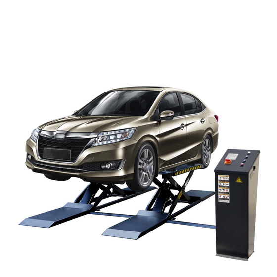
I. PRODUCT FEATURES AND SPECIFICATIONS (See Fig.1) MID-RISED SCISSORS LIFT: MODEL MRL09 · Mid-rised scissor lift, 24V Safety voltage control. . Dual hydraulic synchronization & hydraulic locking system; . Lifting scissors made of thickened steel which are more strong; . Adjustable lift platform length, applicable to vehicles with different wheelbases;... -
Page 4: Installation Requirement
II. INSTALLATION REQUIREMENT A. Tools requirement Screw Set Grease gun Claw Wrench ( for 40-42mm) Socket Head Wrench (8″) Pliers Wrench sets # # # # :(13 、15 、17 、19 Fig.2 B. Equipment storage and installation requirements. The equipment should be stored or installed in a shady, normal temperature, ventilated and dry place. -
Page 5: Step Of Installation
III. STEPS OF INSTALLATION A. Check the parts before assembly, make sure all the parts are completed. Packaged lift, Parts box, Control Cabinet (See Fig. 4) Fig. 4 Move aside the parts, Open the outer packing and check the parts according to the shipment parts list (See Fig.5) Fig. - Page 6 1.3 Open the parts bag , check the parts according to the part list (See Fig.7) Fig. 7 B. SPECIFICATIONS OF CONCRETE 210kg/cm 1. Concrete must be thickness 4”(100mm) minimum and test strength (3,000psi) minimum; floors must be in good condition and no cracks. 2.
- Page 7 3. Install the lift according to the actual installation site. Fig.9 C. Install Oil hose Connect oil hoses of control cabinet and lifts according to the numbers marked Fig. 10...
- Page 8 Part No. Specification 10620072 1/4*650mm 1003285007 1/4*668mm 1003285008 No. ③ 1/4*2530mm 1003285009 No. ① 1/4*2770mm 1003285010 No. ④ 1/4*3780mm No. ⑥ 1/4*4030mm 1003285011 1003285012 No. ② 1/4*2620mm No.⑤ 1/4*3970mm 1003285013 D. Install electrical system Single phase circuit connection 1. Connecting the power supply wires and limit switch wires. (Fig.11) Wire of Wire of Wire of...
- Page 9 2. Circuit diagram (Fig.12) Single Phase Fig.12 3. Part list Description Code Specification Power Switch 380V AC Breaker Breaker Breaker AC Contactor 24V AC High Limit Switch Low Limit Switch Hydraulic Solenoid Valve AC 24V Push Button Single Push Button Down Single Push Button...
- Page 10 E. Limit Device Illustration When lift rise to 47 1/4”(1220mm), slide block touches the limit High Limit Device switch rod, effect the limit switch to stop the rising. This is the maximum lifting height. Fig. 13 2. Low Limit Device When the lift lowers to Platform 12”(300mm) from ground, the...
- Page 11 F. Level two platforms and install anchor bolts 1. Check by level bar and use the shim to adjust the platforms until two platforms are in the same level. Using the Level Bar for measurement 40/41 Using the adjusted shim for the level Fig.15 2.
- Page 12 2.2 Drilling the hole for the anchor bolt with the rotary hammer drill, type the anchor bolt into the ground, and then fasten it with Ratchet spanner. Note: The Torque of anchor bolt is 150 N.m, the length inside ground of anchor bolt must be over 3 1/2”(90mm).
- Page 13 H. Install oil hose cover and anchor the control cabinet. 1. Tidy up the oil hose and wire, cover the oil hose cover and layout the control cabinet. Tidy up the oil hose and wire, and then cover the oil hose cover Fig.
-
Page 14: Exploded View
2. Install the colloidal screw of oil hose cover Type the expansion by screws Fastening Cleaning Drilling colloidal screw Fig. 21 3. Install the control cabinet anchor bolt Install screw Drilling Cleaning Tighten Fig. 22 IV. EXPLODED VIEW Fig.23... - Page 15 PARTS LIST FOR MODEL MRL09 Item Part# Description QTY. Note 1103283001A Platform 1003105001 Upper Slide Block HK023 60*42*33 1103282001A Outer Scissors 10610008 Snap Ring Ф30 1103282008 Piston Rod Connecting shaft φ30*226 10610123 Self Locking Nut M30*3.5 10610108 Washer Ф44*Ф30.5*2 1106582010 Connecting Pin for inner scissors φ45*103...
- Page 16 Item Part# Description QTY. Note 10620069 Wood Screw M4*30 10620070 Colloidal Ф6 10620034 Rubber Pads (120*100*38) 10610070 Rubber Pads (100*70*120) 1103281006 Oil Hose Cover L=840mm 11620036A Oil Hose Cover L=1060mm 11620161 Oil Hose Cover 10620079 Fitting 1/4JIC(M)*1/4JIC(M) 1103283013 10620072 Oil Hose 1/4*650mm 1003285007 Oil Hose 1/4*668mm 1003285008...
- Page 17 Parts list for control cabinet Item Part# Description QTY. Note 63-1 1162K001A Cabinet 10620150 Breaker DZ47-60/3P 25A 63-2 10202046 Breaker 2P 220V 63-3 10202049 Breaker TGB1V-63/1P 6A 63-4 10420084A 24V AC Contactor (KM) 63-5 10420134 24V Transformer (TC) 63-6 10202049 Breaker 1P 6A 63-7 1061K052...
- Page 18 3 Main Cylinder (1003286001) 25-6 25-5 25-4 25-3 25-2 25-1 25-7 25-14 25-8 25-9 25-10 25-11 25-15 25-12 25-10 25-13 Fig.25 Item Part# Description QTY. Note 25-1 1103286003 Bore Weldment 25-2 10620046 Y Ring OSI Ф40*Ф50*6 25-3 10620047 Support Ring Ф40*Ф46*12.5*3 25-4 10209078A Dust Ring Ф40*Ф48*(5~6.5)
- Page 19 4 Secondly Cylinder (1003286001) Fig.26 Item Part# Description QTY. Note 26-1 1103286005 Bore Weldment 26-2 10620049 O ring Ф69*5.3 26-3 1103286016 End Cap 26-4 10620058 O Ring Ф40*3.55 Dust Ring Ф40*Ф48*(5~6.5) 26-5 10209078A 26-6 10201034 Buzzer 26-7 1103286004 Piston Rod 26-8 10620197 O Ring Ф25*3.1(进口...
- Page 20 5. Power Unit 220V/50HZ/Single Phase Fig.27 Power Unit 220V/50Hz Single Phase Item Part No. Description QTY. Note 81400180 Rubber Pad 81400250 Start Capacitor 81400200 Run Capacitor 10420148 Cup Head Bolt with Washer 81400066 Capacitor Cover 81400363 Motor Connecting Shaft 80101015 Manifold Block 81400333 Socket Plug...
- Page 21 81400566 Check Valve 81400420 Solenoid valve coil 81400423 Electric Release Valve 10209149 Lock Washer φ6 85090142 Socket Bolt 81400280 Gear Pump 81400364 Clamp 10209034 Lock Washer φ8 81400295 Socket Bolt 81400290 Filter 81400590 Motor 81400287 Terminal Box Cover 71111231 AMGO name Plate 81400560 Throttle Valve 81400259...
-
Page 22: Test Run
V. TEST RUN 1. Turn on the power after connecting oil system correctly. Push the UP button, and check the rotated direction of the Motor (This is right if lift is upward, otherwise, it is wrong direction of the Motor). Shut off power and exchange the phase connection if the direction is wrong. -
Page 23: Operation Instructions
d. After the platform P1 and P2 were confirmed of acting synchronously, idling test should be done for a complete route of lifting and lowering, and then test with car. e. Once the lift cannot be lowered from the highest position while press DOWN during idling test , turn the 2pcs shutoff valves quickly into oil filling position (Fig.32), then quickly to normal working position (Fig.33). -
Page 24: Maintenance Schedule
lowered continually and stopped at the height 300mm from ground. Keep feet clear off lift, push button DOWN while push the Lowering Alarm Button(black) at the side of control cabinet, the lift will be lowered to ground with alarm tone; 3. -
Page 25: Trouble Shooting
VIII. TROUBLE SHOOTING TROUBLE CAUSE REMEDY 1. Start Button does not work 1. Replace start button 2. AC contactor burned out 2. Replace AC Contactor Motor does not 3. Motor burned out 3. Repair or replace motor 1. Lack of phase (Only for three phase) 1. - Page 27 AMGO HYDRAULIC CORPORATION 1931 Joe Rogers Blvd, Manning, South Carolina, USA Zip: 29102 Tel: (803) 505-6410 Fax: (803) 505-6410 Manual no:72257101 Revised date:2022/08...
Need help?
Do you have a question about the MRL09 and is the answer not in the manual?
Questions and answers