Advertisement
Quick Links
Advertisement

Related Manuals for AMGO Hydraulics MR06


Summary of Contents for AMGO Hydraulics MR06
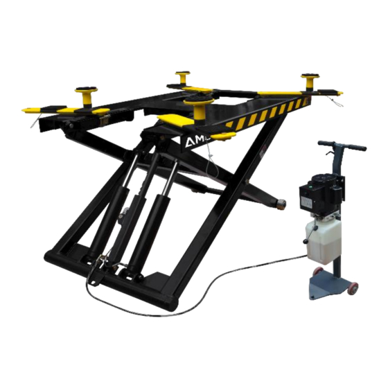
- Page 1 Original PORTABLE MID-RISED LIFT MODEL MR06...
-
Page 2: Table Of Contents
CONTENTS Product Features and Specifications ............1 Installation Requirement................2 Steps of Installation................3 Exploded View..................10 Operation Instruction................17 Maintenance ..................18 Trouble Shooting ..................20 Lift Disposal ...................20... -
Page 3: Product Features And Specifications
I. PRODUCT FEATURES AND SPECIFICATIONS PORTABLE MID-RISED MODEL MR06 Manual safety lock: mechanical safety locks release, No need air source. ● High speed: From 0-1090mm (43”) in just 21 seconds ● Portable design: It is easy to move the whole lift with the power unit stand ●... -
Page 4: Installation Requirement
II. INSTALLATION REQUIREMENT A. TOOLS REQUIRED Screw Set Grease gun Hook spanner (40~42mm) English Spanner (12″) Pliers Wrench sets : # # # # 、15 、17 、19 Fig. 2 B. POWER SUPPLY The electrical source must be 1.0HP minimum. - Page 5 III. INSTALLATION STEPS A. Check the parts before assembly, make sure all the parts are completed. 1. Packaged lift, Parts box, Power Unit and Power Unit Stand. Move the parts aside, open the outer packing and check the parts according to the shipment parts list (See Fig.
- Page 6 3. Check the parts of the parts bag according to the parts bag list (See Fig. 5) Fig.5 B. Install the brake Remove the cover first, then put the brake in and tighten the screws Fig.6...
- Page 7 Then Install hydraulic power unit and fitting (See Fig. 7) Fig. 7...
- Page 8 C. Install oil hose (See Fig. 8) Fig. 8...
- Page 9 D. Install safety device and cable 1. Put the safety device parts as Fig.9 The safety stop needs to be 10mm high, and then install wire cable Fig. 9 Fig. 10 Put the small wire rope into the hole on the screw and then tighten Item Part#...
- Page 10 E. Tighten supporting arm 1. Raise the lift up to 1000mm and lock the safety device, then tighten the self-lock nut. Make sure the supporting arms not move left/right (See Fig. 11) Tighten the self-lock nut Fig. 11...
- Page 11 F Install electric system Connect the power source on the data plate of Motor Note: 1. For the safety of operators, the power wiring must contact the floor well. 2. Pay attention to the direction of rotations when using three phase motors. Single phase motor (See Fig.
-
Page 12: Exploded View
IV. EXPLODED VIEW Model MR06 Fig. 13... - Page 13 PARTS LIST FOR MODEL MR06 Note Item Part# Description QTY. 11640001 Platform 11640002A Stackable Adapter Bracket 11209052B Stackable Adapter (2.5”) 11209051B Stackable Adapter (1.5”) 10201046A Rubber pad assy. 10420138 Socket bolt M6*16 10209134 Rubber pad 11680030C Supporting pad 10209009 Cup Head Bolt...
- Page 14 Item Part# Description QTY. Note 10209005 Self Locking Nut 10640138 Power Unit Stand 10206006 Washer 12 10201005 Split Pin 1003275021 White Roller 1003015002 Oil Hose Assy (include spring) 10201046A Rubber Pad Assy. 10420138 M6*16 Socket Bolt 10209134 Rubber Pad 11680030C Support Frame 10640500A Part Box...
- Page 15 1. CYLINDER (10640116) Fig.14 PARTS FOR HYDRAULIC CYLINDER Item Part# Description QTY. Note 12-1 11640657 Bore Weldment 12-2 11640031A Piston Rod 12-3 10201034 Bleeding Plug 12-4 11203083 Head Cap 12-5 10209078 Dust Ring 12-6 10201032 O - Ring 12-7 10203084 O - Ring 12-8 11203079...
- Page 16 2. MANUAL POWER UNIT (071103) 110V/60HZ/1 phase Fig.15 Parts for Manual power unit Item Part# Description QTY. Note 81400180 Rubber pad 81400250 Start capacitor 81400200 Run capacitor 10420148 Cup head bolt with washer 81400066 Cover for capacitor 81400363 Motor connecting shaft 80101013 Manifold block 10209149...
- Page 17 Item Part# Description QTY. Note 81400290 Filter mesh 81400412 Motor 10420070 Button switch AC contactor 81400559 81400287 Cover of motor terminal box 71111211 AMGO label 81400560 Throttle valve 81400266 Release valve 81400284 Iron plug 81400452 Hair pin 81400451 Handle for release valve 10209020 Plastic ball for arm lock 81400421...
-
Page 18: Operation Instruction
V. OPERATION INSTRUCTIONS 1. Install the oil hose between oil cylinder and power unit, connect with the power supply wire well. The machine can be ready to use. 2. When lifting vehicle, be sure the center of gravity of vehicle must be in the middle of lift, select the suitable adapters , pull the small cable of the yellow support arms to open the lock ,and move the arms to find the support point. -
Page 19: Maintenance
4. Move the lift with the power unit stand (See Fig. 22) Fig. 22 VI. MAINTENANCE SCHEDULE Monthly: 1. Lubricate all moving parts with lubricant (See Fig.23) Fig. 23 2. Check all connectors, bolts and pins to insure proper mounting. 3. - Page 20 Every six months: 1. Make a visual inspection of all moving parts for possible wear, interference or damage. 2. Check all fastener and re-torque. Cylinder Maintenance and Maintenance: In order to extend the life of the cylinder, please follow the following requirements. 1.
-
Page 21: Trouble Shooting
VII. TROUBLE SHOOTING TROUBLE CAUSE REMEDY 1. Button does not work 1. Replace button 2. Wiring connections are not in good 2. Repair all wiring connections condition Motor does not 3. Motor burned out 3. Repair or replace motor 4. Safety Switch is damaged 4. - Page 22 AMGO HYDRAULIC CORPORATION 1931 Joe Rogers Blvd, Manning, South Carolina, Zip:29102 Tel: (803) 505-6410 Fax: (803) 505-6410 Manual Part No.: 72215503 Revision Date: 2022/03...
Need help?
Do you have a question about the MR06 and is the answer not in the manual?
Questions and answers