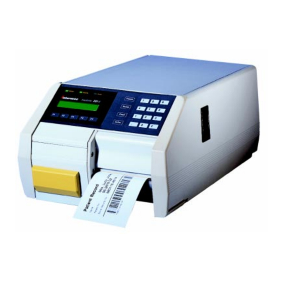
Intermec EasyCoder 201 II Technical Manual
Bar code label printer
Hide thumbs
Also See for EasyCoder 201 II:
- Startup manual (21 pages) ,
- Supplementary manual (14 pages) ,
- Technical manual (9 pages)

Subscribe to Our Youtube Channel
Related Manuals for Intermec EasyCoder 201 II


Summary of Contents for Intermec EasyCoder 201 II
- Page 1 Technical Manual P/N 1-960317-05 Edition 6 September 1998 EasyCoder 201 II Bar Code Label Printer...
-
Page 2: Table Of Contents
Intermec EasyCoder 201 II – Technical Manual CONTENTS Introduction Models Installation Starting Up Setup Parameters Setting Up EasyCoder 201 IIS General Information ... 31 Setting Up EasyCoder 201 IIE & 201 IISA Entering the Setup Mode at Installation... 33 Intermec EasyCoder 201 II Technical Manual Intermec Fingerprint 6.13... - Page 3 Intermec EasyCoder 201 II – Technical Manual CONTENTS, cont'd. Printing Principles Thermal Paper Paper Dimensions Memory Card Adapter Label-taken Sensor Paper Cutter Black Mark Sensor Kit Printhead Replacement Electronics Interfaces Direct Thermal Printing ... 45 Dot Size ... 45 Conversion Table ... 45 General Information ...
- Page 4 Intermec EasyCoder 201 II – Technical Manual CONTENTS, cont'd. Optional Interface Boards ... 74 RS 232C (V24) on "uart1:" ... 75 20 mA Current Loop on "uart1:"... 77 Serial Interface Board ... 80 RS 422/485 Interface Board ... 83 Parallel Interface Board ... 88...
-
Page 5: Fcc, Doc And Vde Notices
Information in this manual is subject to change without prior notice and does not represent a commitment on the part of Intermec Printer AB. © Copyright Intermec PTC AB, 1998. All rights reserved. Published in Sweden. EasyCoder, Fingerprint, and LabelShop are registered trademarks of Intermec Technologies Corp. -
Page 6: Preface
Gives information on how to run and maintain the printer and how to load paper supply. • Intermec Shell 4.01 Standard and Shell 4.01 Enhanced, Startup Manuals Gives information on how to run the Intermec Shell startup program in EasyCoder 201 IIS and EasyCoder 201 IIE respectively • EasyCoder 201 II, Service Manual Gives information on troubleshooting, adjustments and repair of the various EasyCoder 201 II printer models. -
Page 7: Models Easycoder 201 Iis
6 dots/mm printhead density for EAN/UPC bar code printing, or 8 dots/mm for high quality printing of text, bar codes and images. EasyCoder 201 IIS is fitted with the Intermec Fingerprint firmware, which is compatible with the various versions of the Intermec LabelShop label-editing program, the Intermec Windows Driver (optional parallel interface board required), and the Intermec Direct Protocol. -
Page 8: Easycoder 201 Iis
Intermec EasyCoder 201 II – Technical Manual MODELS, cont'd. Feature Print Technique Quick-Mount Printhead Print Width (6 or 8 dots/mm resp.) Media Width Print Length (6 or 8 dots/mm resp.) Print Speed Fonts, expandible 4 times Print Directions for Text, Images, Lines, and Boxes... -
Page 9: Easycoder 201 Iie
It is available with 6 dots/mm printhead density for EAN/UPC bar code printing, or 8 dots/mm for high quality printing of text, bar codes and images. EasyCoder 201 IIE is fitted with the Intermec Fingerprint firmware, which is compatible with the various versions of the Intermec LabelShop label- editing program, the Intermec Windows Driver (optional parallel interface board required), and the Intermec Direct Protocol. -
Page 10: Easycoder 201 Iie
Intermec EasyCoder 201 II – Technical Manual MODELS, cont'd. Feature Print Technique Quick-Mount Printhead Print Width, Standard (6 or 8 dots/mm resp.) Print Width, Big Roll (6 or 8 dots/mm resp.) Media Width, Standard Media Width, Big Roll Print Length (6 or 8 dots/mm resp.) -
Page 11: Easycoder 201 Iisa
Thus, this printer is fitted with special software in its configuration EPROM's and an expanded RAM memory. The printer can be temporarily or permanently connected to a PC for up- or downloading of label texts and formats. The EasyCoder 201 IISA is available with 6 dots/mm printhead density for EAN/UPC bar code printing, or 8 dots/mm for high quality printing of text, bar codes and images. -
Page 12: Easycoder 201 Iisa
Intermec EasyCoder 201 II – Technical Manual MODELS, cont'd. Feature Print Technique Quick-Mount Printhead Print Width (6 or 8 dots/mm resp.) Media Width Print Length (6 or 8 dots/mm resp.) Print Speed Fonts, expandible 4 times Print Directions for Text, Images, Lines, and Boxes... -
Page 13: Installation Installation Check List
“Electronics” and “Interfaces” at the end of this manual. Then go on to next step. Connect the printer to a mains socket as described later on in this chapter. Connect the printer to its host computer by means of a suitable communication cable, as described later in this chapter. -
Page 14: Unpacking
Intermec EasyCoder 201 II – Technical Manual INSTALLATION, cont'd. Unpacking Machine Sign Before starting the installation, carefully examine the delivery for possible damage or missing parts: Open the box and lift the printer, together with the foam-plastic shock absorbers, out of the box. -
Page 15: Mains Connection
Intermec EasyCoder 201 II – Technical Manual INSTALLATION, cont'd. Mains Connection Power On LED P o w e r R e a d y E r r o r P a u s e EasyCoder S e t u p... -
Page 16: Computer Connection
• For Intermec Windows Driver, use the "centronics:" parallel communication channel. • Intermec's standard communication cables and adapters makes it possible to connect the printer directly to the serial or parallel port of an IBM AT, XT or PS-2 personal computer. -
Page 17: Starting Up Startup Files
(autoexec) file, i.e. a program that automati- cally starts running when the printer is turned on. There are five major possibilities: The printer is fitted with the Intermec Shell file-managing program, which allows the operator to choose between a variety of applications and functions. -
Page 18: Messages At Startup
Refer to the Startup Manual of Intermec Shell Standard or Intermec Shell Enhanced respectively for further information. The digits in the lower right corner of the display indicate the version of Intermec Shell. B. Intermec Stand-Alone Program (EasyCoder 201 IISA):... -
Page 19: Setup Parameters General Information
- Rec buff size - Trans buff size /. “Default” refers to the default setup values in the standard configuration EPROM's. A custom-made printer fitted with nonstandard configuration EPROM's may have a different combination of setup values. /. The software is able to detect if any of the optional serial interface boards is fitted. If so, the communication parameters and the size of the buffers are set up separately for each of the serial communication channels "uart1:", "uart2:", and... -
Page 20: Contrast
Up EasyCoder 201 IIS” and “Setting Up EasyCoder 201 IIE & 201 IISA”. • By means of the Terminal Setup option in Intermec Shell, see the Intermec Shell Standard and Enhanced Startup Manuals. • By means of setup files or setup strings. See the Intermec Fingerprint Reference Manual, Direct Protocol Programmer's Guide. - Page 21 Intermec EasyCoder 201 II – Technical Manual SETUP PARAMETERS, cont'd. Serial Communication, cont'd. • Baudrate The baudrate is the transmission speed in bits per second. The following baudrates can be selected: 1200 2,400 4,800 9,600 Max. recommended baudrate for 20 mA current loop...
-
Page 22: New Line
“XON/XOFF; Data to Host: Enable/Disable” decides RS 422 or RS 485 commu- nication. When using the option ”Prot addr: Enable”, the verbosity must be turned off by means of a VERBOFF statement. See Intermec Fingerprint Programmer's Guide for further information. -
Page 23: Detection
If the printer works as expected, there is no need to adjust the label stop sensor, but if the printer starts to feed out labels or tickets in an unexpected manner, check that the paper web passes between the two legs of the fork-shaped sensor and that the sensor has not become dirty or blocked. - Page 24 Note: It is possible to turn off the label stop sensor or black mark sensor for a certain amount of paper feed, and to override the start adjustment and stop adjustment setup by means of the Intermec Fingerprint statement LBLCOND Reference Manual.
-
Page 25: Media Size
Intermec EasyCoder 201 II – Technical Manual SETUP PARAMETERS, cont'd. Media Size • X-start • Width • Length 6 dots/mm (153.9 dpi): 1 dot = 0.165 mm = 6.5 mils 8 dots/mm (203.2 dpi): 1 dot = 0.125 mm = 4.9 mils... - Page 26 Intermec EasyCoder 201 II – Technical Manual SETUP PARAMETERS, cont'd. Media Size, cont'd. 6 dots/mm (153.9 dpi): 1 dot = 0.165 mm = 6.5 mils 8 dots/mm (203.2 dpi): 1 dot = 0.125 mm = 4.9 mils Length serves three purposes: •...
-
Page 27: Print Window (6 Dots/Mm Printhead)
Intermec EasyCoder 201 II – Technical Manual SETUP PARAMETERS, cont'd. Print Window: 6 dots/mm (153.9 dpi) printhead 3.0 mm (0.12") Dot-line on printhead Dot 0 85.3 mm (3.36") PRINT WINDOW Length Origin X-start Width PAPER FEED DIRECTION Dot 12 7" INTERNAL "BIG ROLL”... -
Page 28: Print Window (8 Dots/Mm Printhead)
Intermec EasyCoder 201 II – Technical Manual SETUP PARAMETERS, cont'd. Print Window: 8 dots/mm (203.2 dpi) printhead 3.0 mm (0.12") Dot-line on printhead Dot 0 80.0 mm (3.15") PRINT WINDOW Length Origin X-start Width PAPER FEED DIRECTION Dot 16 7" INTERNAL "BIG ROLL”... -
Page 29: Media Type
(may even be a blank space character or a “white dot” in an image) to allow the strip to be torn off. It is important to select the correct option, so the printer can indicate possible paper errors. Two different error conditions may occur: Error 1005 “Out of paper”... - Page 30 Test label 3 Test label 5 Note: The illustrations of the test labels are not representative of the printout quality to be expected from your printer. First, four test labels intended to facilitate adjustment of the printhead alignment are printed. Then come two or more labels showing the printer's current setup, before the loop starts all over again.
-
Page 31: Performance
Intermec EasyCoder 201 II – Technical Manual SETUP PARAMETERS, cont'd. Performance Horizontal bar code printing (picket fence style) Vertical bar code printing (ladder style) Memory Allocation • Image Buffer • Receive Buffer(s) • Transmit Buffer(s) The Performance setup allows you to select the printer's print speed. -
Page 32: Setting Up Easycoder 201 Iis General Information
• You can change any setup parameter via the Terminal Setup option in Intermec Shell. • You can change the LSS setup via the Setup option of Intermec Shell. • As an alternative, you can also change the setup by means of a... -
Page 33: Setting Up General Information
“Setup Mode” which allows it to be set up in regard of all parameters by means of its own keyboard. The Setup Mode can be accessed via the Intermec Shell program, by the issuing of the Intermec Fingerprint statement pressing the <... -
Page 34: Easycoder 201 Iie & 201 Iisa Entering The Setup Mode At Installation
Press the < Setup > key (this facility can be used anywhere within Intermec Shell). • Set up the printer as described in this chapter. • Return to Intermec Shell by pressing the < Setup > key. B. EasyCoder 201 IISA: • Turn on the power. -
Page 35: Using The Keyboard In The Setup Mode
Intermec EasyCoder 201 II – Technical Manual SETTING UP EASYCODER 201 IIE & 201 IISA, cont'd. Using the Keyboard in the Setup Mode 201 IIE 201 IISA Application Used to view the current value of the LSS setup. Used to move up between menus, to scroll backwards between options in stacks, and to decrease the value of the contrast or the LSS/BMS 1 step. -
Page 36: Setup Mode Overview, Part 1
Intermec EasyCoder 201 II – Technical Manual SETTING UP EASYCODER 201 IIE & 201 IISA, cont'd. Setup Mode Overview, Part 1 SETUP: min CONTRAST max CONTRAST SETUP: SER-COM: SER-COM UART1 UART2 UART3 If an optional interface board with at least one serial channel... -
Page 37: Setup Mode Overview, Part 2
Intermec EasyCoder 201 II – Technical Manual SETTING UP EASYCODER 201 IIE & 201 IISA, cont'd. Setup Mode Overview, Part 2 SETUP: SERVICE SETUP: SERVICE: PASSWD: MEDIA SIZE Password: 1138 SERVICE: MEDIA TYPE SERVICE: PRINT DEFS SERVICE: PERFORMANCE SERVICE: MEMORY ALLOC •... -
Page 38: Contrast
Intermec EasyCoder 201 II – Technical Manual SETTING UP EASYCODER 201 IIE & 201 IISA, cont'd. Contrast Serial Communication (SER-COM) • Baudrate • Parity • Character Length • Stop Bits • Flow Control • New Line Detection • LSS Adjustment •... -
Page 39: Technical Manual
Intermec EasyCoder 201 II – Technical Manual SETTING UP EASYCODER 201 IIE & 201 IISA, cont'd. Detection, cont'd. Label (w gaps): Put a piece of paper with backing paper between the two parts of the sensor. The cursor should appear at the left side of the... -
Page 40: Technical Manual
Intermec EasyCoder 201 II – Technical Manual SETTING UP EASYCODER 201 IIE & 201 IISA, cont'd. Detection, cont'd. If you cannot make the LSS/BMS work correctly by means of the potentiometer, you must change its light intensity level. You can check the present level of the LSS/BMS emitter by pressing the <... -
Page 41: Technical Manual
Intermec EasyCoder 201 II – Technical Manual SETTING UP EASYCODER 201 IIE & 201 IISA, cont'd. Detection, cont'd. Feed adjustment: STARTADJ: [0]: The present value of the start adjustment is displayed within brackets. Accept the value by pressing < Enter >, or type a new value and press <... -
Page 42: Service
Intermec EasyCoder 201 II – Technical Manual SETTING UP EASYCODER 201 IIE & 201 IISA, cont'd. Service Media Size • X-start • Width • Length The Service part of the Setup Mode is protected by a password to avoid unauthorized access. To enter Service, press < Enter >. A... -
Page 43: Media Type
Intermec EasyCoder 201 II – Technical Manual SETTING UP EASYCODER 201 IIE & 201 IISA, cont'd. Media Type Print Defines • Printhead Resistance • Paper Type • Testprint A stack of five menus will be displayed, with the current media type... -
Page 44: Performance
Intermec EasyCoder 201 II – Technical Manual SETTING UP EASYCODER 201 IIE & 201 IISA, cont'd. Print Defines, cont'd. Performance Memory Allocation Testprint, cont'd. “Check status” reports four possible error conditions: • Printhead lifted. • Label not removed. • Printer out of paper. -
Page 45: Leaving The Setup Mode
Return to “Setup; Service” menu Exit Setup Mode If you have entered the Setup Mode from the Intermec Shell or the Intermec Stand-Alone program, you will return to the program in question when you press < Setup > or < Save > respectively. -
Page 46: Printing Principles Direct Thermal Printing
These black imprint can be combined into patterns, which make up letters, bar codes, or images. The basis for all measures and positioning in the Intermec Finger- print programming language is the size of printhead dots. For example, in an 8 dots/mm printhead, each dot has a nominal size of 0.125 mm (4.9 mils). -
Page 47: Thermal Paper General Information
They have been specifically engineered with Intermec printers to provide the highest printout quality and the best possible read rates. Intermec offers two quality grades of direct thermal paper for the EasyCoder range of printers: • Premium Quality: Top-coated papers with high demands on printout quality and resistance against moisture, plasticisers and vegetable oils. -
Page 48: Setup Options
Due to the increased amount of energy to the printhead, they shall be used with extreme care. Further, a more frequent cleaning of the printhead is recommended with these setup options. Consult your local Intermec reseller or sales representative for more information. Energy Level Paper Sensitivity High... -
Page 49: Additional Setup Options
Intermec EasyCoder 201 II – Technical Manual THERMAL PAPER, cont'd. Additional Setup Options Additional setup options are included in the “Paper Type” stack of menus for compatibility reasons. 6 dots/mm printers: KANZAKI 86S, RICOH 120 LAB/LAM, RICOH 130 LAB/LAM 8 dots/mm printers:... -
Page 50: Paper Dimensions Roll Size, Standard Printers (Internal 4.9" Paper Roll)
Intermec EasyCoder 201 II – Technical Manual PAPER DIMENSIONS Roll Size, Standard Printers (internal 4.9" paper roll) Bobbin (Ø 38 mm/1.5") Adapter (Ø 76 mm/3") Note: This is the recommended maximum thickness. Thicker web may be used at the possible expense of an impaired printout quality. -
Page 51: Roll Size, "Big Roll" Printers (Internal 7" Paper Roll)
Intermec EasyCoder 201 II – Technical Manual PAPER DIMENSIONS, cont'd. Roll Size, “Big Roll” Printers (internal 7" paper roll) Bobbin (Ø 38 mm/1.5") Adapter (Ø 76 mm/3") Note: This is the recommended maximum thickness. Thicker web may be used at the possible expense of an impaired printout quality. -
Page 52: Non-Adhesive Strip
Intermec EasyCoder 201 II – Technical Manual PAPER DIMENSIONS, cont'd. Non-adhesive Strip NON-ADHESIVE STRIP NORMAL ROLL PRINTERS: Web width: Maximum (standard) ... : Minimum ... : “BIG ROLL” PRINTERS (7" internal roll): Web width: Maximum (standard) ... : Minimum ... : 89.0 mm... -
Page 53: Self-Adhesive Strip
Intermec EasyCoder 201 II – Technical Manual PAPER DIMENSIONS, cont'd. Self-adhesive Strip SELF-ADHESIVE STRIP NORMAL ROLL PRINTERS: Web width (incl. backing paper): Maximum ... : Minimum ... : Paper width (excl. backing paper): Maximum ... : Minimum ... : Backing paper: The backing paper must not extend more than 1.6 mm (0.06") outside the... -
Page 54: Self-Adhesive Labels
Intermec EasyCoder 201 II – Technical Manual PAPER DIMENSIONS, cont'd. Self-adhesive Labels SELF-ADHESIVE LABELS PAPER FEED DIRECTION /. The last third of a label with maxi- mum length cannot be used for print- ing! Also see “Max. printable length”. NORMAL ROLL PRINTERS: Web width (incl. -
Page 55: Tickets And Tags
Intermec EasyCoder 201 II – Technical Manual PAPER DIMENSIONS, cont'd. Tickets and Tags TICKETS & TAGS PAPER FEED DIRECTION /. The last third of a ticket or tag with maximum length cannot be used for printing! Also see “Max. printable length”. -
Page 56: Tickets With Black Mark (Normal Roll Printers)
Intermec EasyCoder 201 II – Technical Manual PAPER DIMENSIONS, cont'd. Tickets with Black Mark TICKETS PAPER FEED DIRECTION /. The last third of a ticket or tag with maximum length cannot be used for printing! Also see “Max. printable length”. -
Page 57: Tickets With Black Mark ("Big Roll" Printers)
Intermec EasyCoder 201 II – Technical Manual PAPER DIMENSIONS, cont'd. Tickets with Black Mark TICKETS PAPER FEED DIRECTION /. The last third of a ticket or tag with maximum length cannot be used for printing! Also see “Max. printable length”. -
Page 58: Memory Card Adapter Memory Card Types
SRAM (Static Random Access Memory), each in several sizes in regard of memory capacity, see below. • OTPROM cards can only be read by the Intermec Fingerprint firmware after being preprogrammed using e.g. the Intermec Configuration program. Once programmed, they cannot repro- grammed. -
Page 59: Fitting A Memory Card
Intermec EasyCoder 201 II – Technical Manual MEMORY CARD ADAPTER, cont'd. Fitting a Memory Card IMPORTANT! The printer must be OFF when the memory card is inserted or removed. Removing a Memory Card Turn off the power to the printer and open the right-hand door. -
Page 60: Label-Taken Sensor General Information
Intermec EasyCoder 201 II – Technical Manual LABEL-TAKEN SENSOR General Information The Label-Taken Sensor (LTS) is a device, which enables the printer's software to detect if the latest printed label, ticket, tag etc. has been removed before printing another copy. -
Page 61: Adjusting The Sensitivity
LTS works properly. If a proper adjustment cannot be achieved by means of the potentiometer, fit or remove the strap on P-14 (see above). Another way is to make a simple Intermec Fingerprint program that checks the printer's status using the see Intermec Fingerprint manuals). -
Page 62: Program Example
FONT "SW030RSN" PRTXT "HELLO" LTS& ON PRINTFEED 10 In Intermec Fingerprint versions earlier than 6.0, the status of the label-taken sensor must be polled by a example as above can be run by a program like this: FONT "SW030RSN.1" PRTXT "HELLO"... -
Page 63: Paper Cutter General Information
Fingerprint Reference Manual or the Intermec Direct Protocol Programmer's Guide. In EasyCoder 201 IISA, the cutter can be turned on or off by means of a menu in the Set Mode, see the Intermec Stand-Alone Concept; Operating Instructions. ) for... -
Page 64: Maintenance
Intermec EasyCoder 201 II – Technical Manual PAPER CUTTER, cont'd. Maintenance Turn off the power before cleaning. Keep fingers away from cutting parts. Dimensions The cutter requires no maintenance other than occasional cleaning of the outside surfaces and the cutting parts. -
Page 65: Black Mark Sensor Kit General Information
Intermec EasyCoder 201 II – Technical Manual BLACK MARK SENSOR KIT General Information Bracket The Black Mark Sensor Kit can be fitted to replace the standard label-taken sensor in such EasyCoder 201 II printers that do not use an internal backing paper rewind unit. The Black Mark Sensor... -
Page 66: Printhead Replacement Step-By-Step Instructions
Intermec EasyCoder 201 II – Technical Manual PRINTHEAD REPLACEMENT Step-by-Step Instructions Screw Bracket Printhead assy. The quick-mount thermal printhead is designed to be easy to replace. Proceed as follows: Turn off the printer. Open the right-hand door and the front flap. (In case of cutter- equipped printer, tilt the cutter forward). -
Page 67: Technical Manual
Intermec EasyCoder 201 II – Technical Manual PRINTHEAD REPLACEMENT, cont'd. Step-by-Step Instructions, cont'd. Close the front flap and side door. Turn on the power. The printer will automatically reset itself to the characteristics of the printhead in regard of head resistance and density. -
Page 68: Electronics Accessing The Cpu Board
Intermec EasyCoder 201 II – Technical Manual ELECTRONICS Accessing the CPU Board WARNING! Disconnect the power cord before removing the cover plate. Dangerous voltage! The CPU board is situated in the electronics compartment on the left side of the printer's centre-line wall. To gain access to the electronics... -
Page 69: Cpu Board
Intermec EasyCoder 201 II – Technical Manual ELECTRONICS, cont'd. CPU Board 971700,10 LAYER P-14 The CPU board contains a number of jumpers and socket-mounted circuits, which decide how the printer will work. IC-1 IC-3 IC-2 IC-4 P-24 P-22 Before touching the CPU board, carefully read the following instructions: •... -
Page 70: Intermec Fingerprint Eprom's
Intermec EasyCoder 201 II – Technical Manual ELECTRONICS, cont'd. Intermec Fingerprint EPROM's Configuration EPROM's EPROM Size Strap /. 27C010 EPROM's will work with strap in either upper or lower position. The EasyCoder 201 II printers are usually fitted with four EPROM's (Erasable Programmable Read-Only Memory). -
Page 71: Eprom/Flash Memory Strap
If the printer is kept turned on less than full working hours, it is recommended to leave the power on overnight at least once a week. Do not leave the printer off for several weeks (e.g. during holidays) without having made a full memory backup on a computer disk. -
Page 72: Gal Circuit
RTC is fitted on IC-14, the time and date do not have to be set manually each time the printer is started. (See variables in the Intermec Fingerprint Reference Manual or in the Intermec Direct Protocol Programmer's Guide). When installing an RTC, be careful to fit it with the semi-circular marking pointing downwards, as seen when the CPU board is fitted in the printer. -
Page 73: Potentiometers
Intermec EasyCoder 201 II – Technical Manual ELECTRONICS, cont'd. Potentiometers Thermal Printer 201 Model # LISTED 65B5 LR67809 1-201011-11 Serial # MADE IN SWEDEN geprüfte Sicherheit 50105 115-230V 2.6-1.3A 50-60Hz N309 This equipment complies with the requirements for a Class A computing device in FCC Rules Part 15 Subpart J. -
Page 74: Interfaces Communication Port "Uart1
Intermec EasyCoder 201 II – Technical Manual INTERFACES Communication Port "uart1:" UART = Universal Asynchronous Receiver and Transmitter Thermal Printer 201 Model # LISTED 65B5 LR67809 1-201011-11 Serial # MADE IN SWEDEN geprüfte Sicherheit 50105 115-230V 2.6-1.3A 50-60Hz N309 This equipment complies with the requirements for a Class A computing device in FCC Rules Part 15 Subpart J. -
Page 75: Optional Interface Boards
Intermec EasyCoder 201 II – Technical Manual INTERFACES, cont'd. Optional Interface Boards Thermal Printer 201 Model # LISTED 65B5 LR67809 1-201011-11 Serial # MADE IN SWEDEN geprüfte Sicherheit 50105 115-230V 2.6-1.3A 50-60Hz N309 This equipment complies with the requirements for a Class A computing device in FCC Rules Part 15 Subpart J. -
Page 76: Rs 232C (V24) On "Uart1
Intermec EasyCoder 201 II – Technical Manual INTERFACES, cont'd. RS 232C (V24) on "uart1:" P-10 (DTR/RTS select) P-15 (Interface select) /. Warning! Be careful not to enable the external 5V unintentionally, which may cause harm to the terminal, PC or other... -
Page 77: Technical Manual
CTS open (pulled up in the printer). Cable configuration: The following ready-made RS 232C connection cables can be ordered from Intermec. Cables procured from other sources should follow the same wiring principles. Note: Be careful not to connect the external +5V unintentionally, which may harm your computer or terminal. -
Page 78: Ma Current Loop On "Uart1
Intermec EasyCoder 201 II – Technical Manual INTERFACES, cont'd. 20 mA Current Loop on "uart1:" IC-40 & IC-41 (opto-couplers) P-15 (interface select) The 20 mA current loop interface is a single-ended, full duplex serial interface which uses current instead of voltage to transmit signals on a four-wire line. -
Page 79: Technical Manual
Intermec EasyCoder 201 II – Technical Manual INTERFACES, cont'd. 20 mA Current Loop on "uart1:", cont'd. On the CPU board, check: Opto-couplers must be fitted on IC-40 and IC-41. These are not included as standard and must be ordered separately. -
Page 80: Technical Manual
Intermec EasyCoder 201 II – Technical Manual INTERFACES, cont'd. 20 mA Current Loop on "uart1:", cont'd. Printer active transmitter/active receiver Transmitter Receiver Printer active transmitter/passive receiver Transmitter Receiver The examples below illustrate two of four possible cases of the printer or host computer being active transmitter or receiver, i.e. -
Page 81: Serial Interface Board
Intermec EasyCoder 201 II – Technical Manual INTERFACES, cont'd. Serial Interface Board The Serial Interface Board adds two serial communication ports ("uart2:" and "uart3:") to the standard serial communication port ("uart1:"). The Serial Interface Board may either be bought separately as a kit complete with installation instructions, or be factory installed. -
Page 82: Technical Manual
Intermec EasyCoder 201 II – Technical Manual INTERFACES, cont'd. Serial Interface Board, cont'd. The following straps and circuits are used to set up the desired type of interface on the communication ports "uart2:" and "uart3:". Communication Port "uart2:" There are no straps for controlling the RS 232C interface on "uart2:". -
Page 83: Technical Manual
Intermec EasyCoder 201 II – Technical Manual INTERFACES, cont'd. Serial interface Board, cont'd. "uart2:" "uart3:" DB25 female DB25 male GNDC GNDC TXDA TXDB RXDA RXDB RTSA RTSB CTSA CTSB DSRA DSRB GNDI GNDI – – – +20M1 – –20M1 –... -
Page 84: Rs 422/485 Interface Board
Intermec EasyCoder 201 II – Technical Manual INTERFACES, cont'd. RS 422/485 Interface Board The RS 422/485 Interface Board adds two more serial communica- tion ports ("uart2:" and "uart3:") to the standard serial communica- tion port ("uart1:"). The RS 422/485 interface is galvanically insulated from the printer in order to avoid electrical interference. - Page 85 This port can be used for either RS 422 or RS 485 interface: RS 422 is a point-to-point serial interface, which can connect one printer to a host computer at a distance of up to 1,200 metres (4,000 ft.) using a four-wire screened cable. The transmission is full duplex, i.e.
-
Page 86: Technical Manual
Intermec EasyCoder 201 II – Technical Manual INTERFACES, cont'd. RS 422/485 Interface Board, cont'd. P-11 P-10 The following straps are used to set up the desired interface: Communication Port "uart2:" (RS 422/485) Selects 2- or 4-wire communication (see text on board). -
Page 87: Technical Manual
Intermec EasyCoder 201 II – Technical Manual INTERFACES, cont'd. RS 422/485 Interface Board, cont'd. RS 422 POINT-TO-POINT (printer to printer) Screened twisted 4-line cable (approx. 50 pf/m) PRINTER P-11 P-10 100 ohm 100 ohm +VEE GNDE P-8 and P-9 strapped on both units. -
Page 88: Technical Manual
Intermec EasyCoder 201 II – Technical Manual INTERFACES, cont'd. RS 422/485 Interface Board, cont'd. Address straps (P-7): STRAP: Address 0 Address 1 Address 2 Address 3 Address 4 Address 5 Address 6 Address 7 Address 8 Address 9 Address 10... -
Page 89: Parallel Interface Board
Intermec EasyCoder 201 II – Technical Manual INTERFACES, cont'd. Parallel Interface Board The Parallel Interface Board adds one extra parallel communication port ("centronics:") to the standard serial communication port ("uart1:"). The Parallel Interface Board may either be bought separately as a kit complete with installation instructions, or be factory installed. -
Page 90: Technical Manual
Intermec EasyCoder 201 II – Technical Manual INTERFACES, cont'd. Parallel Interface Board, cont'd. /. A jumper must be fitted on either S-2 or S-3. Three different straps can be fitted on the Parallel Interface Board: External +5V Jumper fitted on connector P-2 enables external +5V (max. 200 mA) on pin 18. -
Page 91: Technical Manual
/SLCTIN 37–38 Housing Note: The PE signal (Paper End) on pin 12 requires an error-trapping routine to be included in the Intermec Fingerprint software, activat- ing the statements. Here is an example on how BUSY READY such a routine may be written:... -
Page 92: Industrial Interface Board
The input and output signals can be read by means of the Intermec Fingerprint function output signals can be controlled by The Industrial Interface Board can either be bought separately as a kit complete with installation instructions, or be factory installed. -
Page 93: Technical Manual
Intermec EasyCoder 201 II – Technical Manual INTERFACES, cont'd. Industrial Interface Board, cont'd. Communication Port "uart3:" RS 232C: There are no straps for controlling the RS 232C interface on "uart3:". External +5V: External +5V ( max. 200 mA) can be made available on pin 16 by fitting a strap on P-1. -
Page 94: Technical Manual
Intermec EasyCoder 201 II – Technical Manual INTERFACES, cont'd. Industrial Interface Board, cont'd. "uart3:" Remarks DB25 female GNDC Cable shield TXDB Transmitted data from printer RXDB Received data to printer RTSB RTS from printer CTSB CTS to printer DRSB DSR to printer... -
Page 95: Technical Manual
Intermec EasyCoder 201 II – Technical Manual INTERFACES, cont'd. Industrial Interface Board, cont'd. Example of an IN port TIL193B Signal Min. Typical Input Voltage High 10V Input Voltage Low -1V Example of an OUT port REL1 OUT1 Max AC Load Breaking Capacity Current max.
Need help?
Do you have a question about the EasyCoder 201 II and is the answer not in the manual?
Questions and answers