Table of Contents
Advertisement
Quick Links
Advertisement
Table of Contents

Related Manuals for Advantech iDAQ-817


Summary of Contents for Advantech iDAQ-817
- Page 1 User Manual iDAQ-817, iDAQ-821 Analog Input and output Industrial DAQ Modules...
- Page 2 No part of this manual may be reproduced, copied, translated, or transmitted in any form or by any means without the prior written permission of Advantech Co., Ltd. The information provided in this manual is intended to be accurate and reliable.
- Page 3 This product has passed the CE test for environmental specifications when shielded cables are used for external wiring. We recommend the use of shielded cables. This type of cable is available from Advantech. Please contact your local supplier for ordering information.
- Page 4 Document Feedback To assist us with improving this manual, we welcome all comments and constructive criticism. Please send all such feedback in writing to support@advantech.com. Packing List Before system installation, check that the items listed below are included and in good condition.
- Page 5 In accordance with IEC 704-1:1982 specifications, the sound pressure level at the operator's position does not exceed 70 dB (A). DISCLAIMER: These instructions are provided according to IEC 704-1 standards. Advantech disclaims all responsibility for the accuracy of any statements contained herein. iDAQ-817_821 User Manual...
- Page 6 Der arbeitsplatzbezogene Schalldruckpegel nach DIN 45 635 Teil 1000 beträgt 70dB(A) oder weiger. Haftungsausschluss: Die Bedienungsanleitungen wurden entsprechend der IEC- 704-1 erstellt. Advantech lehnt jegliche Verantwortung für die Richtigkeit der in die- sem Zusammenhang getätigten Aussagen ab. iDAQ-817_821 User Manual...
- Page 7 Safety Precautions - Static Electricity Follow these simple precautions to protect yourself from harm and the products from damage. To avoid electrical shock, always disconnect the power from the PC chassis before manual handling. Do not touch any components on the CPU card or other cards while the PC is powered on.
- Page 8 iDAQ-817_821 User Manual viii...
-
Page 9: Table Of Contents
Figure 2.4 Analog output signal connection......... 8 2.3.3 Pin Assignment ................9 Figure 2.5 Pin Assignment for iDAQ-817........9 Table 2.1: Pin Assignment for iDAQ-817........9 Figure 2.6 Pin Assignment for iDAQ-821........9 Table 2.2: Pin Assignment for iDAQ-821........9... - Page 10 Field Application Notes ................18 3.5.1 DAC Code Change Glitch............18 3.5.2 Output Status When Changing Range ........18 Appendix A Specifications........19 Analog Input (iDAQ-817)................. 20 Analog Output (iDAQ-821)..............21 General ....................22 Function Block ..................22 Appendix B System Dimensions......23 System Dimensions ................
-
Page 11: Chapter 1 Start Using Idaq-817/821
Chapter Start Using iDAQ-817/... -
Page 12: Overview
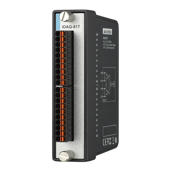
This chapter provides an overview of Advantech industrial data acquisition (iDAQ) modules for iDAQ-817 and iDAQ-821, ranging the product lineups, features and accessories. iDAQ-817 is an 8-channel analog input module. It features a maximum sampling rate of 200kS/s multiplexing, high common-mode voltage 275 V , input isolation, and low-pass filter. -
Page 13: Product Features
Driver Installation The driver package could be found on Advantech Support Portal (https://www.advan- tech.com/support). Search for iDAQ on the support portal, then the corresponding driver/SDK package can be found. You’ll get the XNavi installer after the download session finishes. -
Page 14: Software Utility
All these software packages are available on the Advantech website: http://www.advantech.com/. The Advantech Navigator is a utility that allows you to set up, configure and test your device, and later store your settings in a proprietary database. -
Page 15: Chapter 2 Installation Guide
Chapter Installation Guide... -
Page 16: Initial Unpacking Check
Initial Unpacking Check Before you install your iDAQ modules, please make sure you have the following nec- essary components when unpacking the package: DAQ modules*1 Startup manual*1 Terminal blocks If anything in the packing list is missing, please contact your local support for further assistance. -
Page 17: Signal Connection And Pin Assignment
Signal Connection and Pin Assignment 2.3.1 Analog Input Connection An analog input channel measures the voltage or current of the external sensor or source, converts the value into a digital form of data by an analog-to-digital converter (ADC), and passes it through a galvanic isolator to the internal circuit. Figure 2.2 shows the analog input signal connection. -
Page 18: Analog Output Connection
There is only one ADC in the device. An analog multiplexer selects one of the analog input channels at a time to be measured by the ADC. Therefore, the sample rate of the ADC is shared by all enabled channels. Refer to Appendix A Specifications for the sample rate supported. -
Page 19: Pin Assignment
2.3.3 Pin Assignment iDAQ-817 Figure 2.5 Pin Assignment for iDAQ-817 Table 2.1: Pin Assignment for iDAQ-817 Pin Name Description Pin Number AI<n>+ Analog input n positive terminal, n = 0~7 2, 4, 6, … , 18 AI<n>- Analog input n negative terminal, n = 0~7 3, 5, 7, …... - Page 20 iDAQ-817_821 User Manual...
-
Page 21: Chapter 3 Function Details
Chapter Function Details... -
Page 22: Function Details
Function Details The iDAQ system relys on the chassis module as a platform to bring all the signals together in order to achieve functions including synchronization, data streaming, and timing control. This chapter describes all the functions that the iDAQ system provides and how they work. - Page 23 Figure 3.2 Buffered analog input acquisition. The start and stop mechanism of the data acquisition are controlled by the start trig- ger and stop trigger respectively. When configuration is completed, the acquisition engine of the iDAQ chassis is at standby state. After receiving a start trigger, acquisi- tion becomes active and each rising edge of the sample clock acquires one analog input sample.
-
Page 24: High Common-Mode Amplifier
Figure 3.4 Start and stop of the analog input acquisition with delay. Buffered analog input acquisition has several advantages over instant analog input acquisition: The start and stop time of acquisition (or duration of the acquisition) can be pre- cisely controlled by hardware trigger signals. -
Page 25: Analog Multiplexer
3.2.5 Analog Multiplexer The analog multiplexer routes one of the analog input channels at a time (one for sin- gle-ended configuration, and two for differential configuration) to the PGIA and ADC to be measured. This mechanism is called channel scanning. It realizes multiple channel measurement using only one ADC at a cost of sharing ADC sample rate among all scanned channels. - Page 26 Figure 3.7 Buffered analog output waveform generation The start and stop of the generation are controlled by the start trigger and stop trig- ger, respectively. When configuration is completed, the acquisition engine of the iDAQ chassis is at standby state. After receiving a start trigger, generation becomes active and each rising edge of the sample clock converts one analog output sample.
-
Page 27: Analog Output Isolation
Buffered analog output waveform generation has several advantages over static ana- log output update: The start and stop time of generation (or duration of the generation) can be pre- cisely controlled by hardware trigger signals. DAC conversion rate is configurable, and update rate can be much higher by ... -
Page 28: Field Application Notes
Figure 3.10 Device description shown in Navigator Field Application Notes Here are some notes related to field applications. They are mainly about the consid- erations of safety, especially the output function in some machine-controlling scenar- ios. 3.5.1 DAC Code Change Glitch When the output voltage or current of an analog output channel changes, glitches may be observed. -
Page 29: Appendix A Specifications
Appendix Specifications... -
Page 30: Analog Input (Idaq-817)
Analog Input (iDAQ-817) Channels: 8 differential Analog-to-digital converter (ADC) resolution: 16 bits Analog-to-digital converter (ADC) type: Successive approximation (SAR) Input range: ±10 V or ±20 mA, each channel can be configured independently by software Input common-mode voltage range: ±275 V max. -
Page 31: Analog Output (Idaq-821)
Analog Output (iDAQ-821) Channels: 4 Digital-to-analog converter (DAC) resolution: 16 bits Output range: 0 ~ +5 V, 0 ~ +10 V, ±5 V, ±10 V, 0 ~ 20 mA, 4 ~ 20 mA, software selectable per channel Output coupling: DC ... -
Page 32: General
General Power consumption from chassis – iDAQ-817: 1,000 mW typ./1,250 mW max. – iDAQ-821: 675 mW typ./ 2,900 mW max. Module dimensions: 100 x 80 x 25 mm (3.94 x 3.15 x 0.98 in.) Operating temperature: -20 °C to 60 °C (-4 °F to 140 °F) ... -
Page 33: Appendix B System Dimensions
Appendix System Dimensions... -
Page 34: System Dimensions
System Dimensions iDAQ-817 iDAQ-817 AI0+ 8-ch, 16-bit, 200kS/s, ±275V Common-Mode Voltage AI0- ±10V / ±20mA Analog Input AI1+ AI1- AI2+ AI2- AI3+ AI0+ AI3- AI0- AI7+ AI4+ AI7- AI4- iDAQ-817 AI5+ AI5- AI6+ AI6- AI7+ AI7- iDAQ-817_821 User Manual... - Page 35 iDAQ-817_821 User Manual...
- Page 36 No part of this publication may be reproduced in any form or by any means, such as electronically, by photocopying, recording, or otherwise, without prior written permission from the publisher. All brand and product names are trademarks or registered trademarks of their respective companies. © Advantech Co., Ltd. 2021...
Need help?
Do you have a question about the iDAQ-817 and is the answer not in the manual?
Questions and answers