Table of Contents
Advertisement
Quick Links
Advertisement
Table of Contents

Related Manuals for Advantech ROM-5880


Summary of Contents for Advantech ROM-5880
- Page 1 User Manual ROM-5880 ® Rockchip RK3568 Cortex -A55 SMARC 2.1 Computer-on- Module...
- Page 2 No part of this manual may be reproduced, copied, translated, or transmitted in any form or by any means without the prior written permission of Advantech Co., Ltd. The information provided in this manual is intended to be accurate and reliable.
- Page 3 Acknowledgments ARM is a trademark of ARM Corporation. Rockchip is a trademark of Rockchip Corporation. All other product names or trademarks are properties of their respective owners. ROM-5880 User Manual...
- Page 4 Product Warranty (2 years) Advantech warrants the original purchaser that each of its products will be free from defects in materials and workmanship for two years from the date of purchase. This warranty does not apply to any products that have been repaired or altered by persons other than repair personnel authorized by Advantech, or products that have been subject to misuse, abuse, accident, or improper installation.
- Page 5 Increase the separation between the equipment and receiver. Connect the equipment into an outlet on a circuit different from that to which the receiver is connected. Consult the dealer or an experienced radio/TV technician for assistance. ROM-5880 User Manual...
- Page 6 Packing List Before system installation, check that the items listed below are included and in good condition. If any item does not accord with the list, contact your dealer immediately. 1 x ROM-5880 4 x Screws 1 x China ROHS ...
- Page 7 Part No. Description ROM-5880CQ-REA1 SMARC2.1 RK3568 2.0GHz, 2GBDDR, 16GB eMMC, 0~60°C ROM-5880CQ-RFA1 SMARC2.1 RK3568 2.0GHz, 4GBDDR, 32GB eMMC, 0~60°C ROM-5880WQ-REA1 SMARC2.1 RK3568 2.0GHz, 2GBDDR, 16GB eMMC, -40~85°C SOM-DB2510-R0A1 SMARC R2.1 Devel. Board Rev. A1 for RISC Module ROM-5880 User Manual...
- Page 8 Optional Accessories Part No. Description 1700022373-01 Debug port cable for ROM-5880 ROM-ED20-00A1E Debug port adapter board 1970005667T001 Heat spreader 1970004755T001 Heat sink 1930004835 Screws for heat spreader and semi heat sink 96PSA-A36W12R1-3 ADAPTER 100-240V 36W 12V 3A 1700001524 Power cord 3P UL 10A 125V 180 cm...
- Page 9 The equipment has been dropped and damaged. – The equipment shows obvious signs of breakage. DISCLAIMER: These instructions are provided according to IEC 704-1 standards. Advantech disclaims all responsibility for the accuracy of any statements contained herein. ROM-5880 User Manual...
- Page 10 Do not touch any components on the CPU card or other cards while the PC is powered on. Disconnect the power before making any configuration changes. A sudden rush of power after connecting a jumper or installing a card may damage sensitive electronic components. ROM-5880 User Manual...
-
Page 11: Table Of Contents
GPIO ................... 33 3.1.9 RTC..................... 34 3.1.10 Watchdog..................34 3.1.11 CAN .................... 35 Chapter System Recovery.......37 Create update.img................... 38 Using SDDiskTool to Create an Upgrade SD ......... 39 Upgrade or Recovery ROM-5880 ............40 Chapter Advantech Services ......41 XXX-XXXX User Manual... - Page 12 RISC Design-in Services ................ 42 Contact Information................. 45 Global Service Policy ................46 5.3.1 Warranty Policy................46 5.3.2 Repair Process ................47 XXX-XXXX User Manual...
- Page 13 Chapter Introduction This chapter gives background information on the ROM-5880. Sections include: Introduction Specifications...
-
Page 14: Chapter 1 Introduction
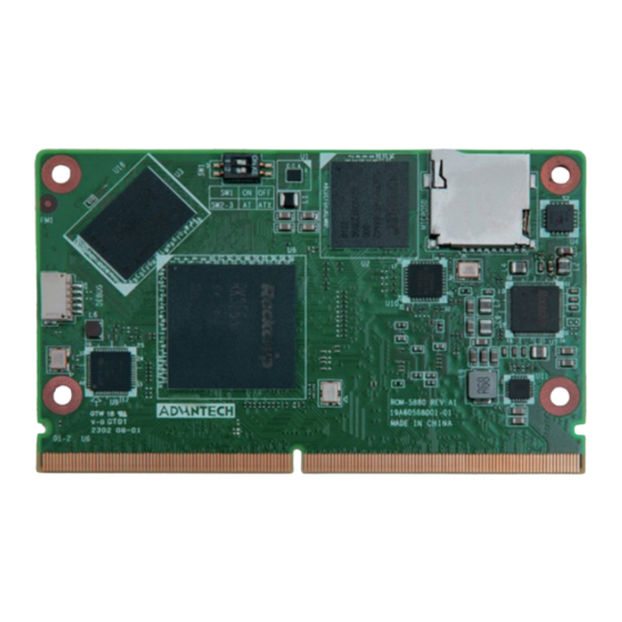
Introduction The Advantech ROM-5880 SMARC 2.1 Computer-on-Module is powered by the Rockchip RK3568 SOC, which includes the Quad-Core Arm Cortex-A55 processor and Arm Mali-G52 3D graphics engine. It provides rich display interfaces: HDMI 4K @ 60Hz, LVDS or DSI or eDP to meet different requirements. It also features USB 3.0, PCIe 3.0, SATA, Gigabit Ethernet, MIPI-CSI for embedded applications. -
Page 15: Mechanical Specifications
Environmental Specifications Operating temperature: 0 ~ 60°C / -40 ~ 85°C Operating humidity: 5 ~ 95% relative humidity, non-condensing Storage temperature: -40 ~ 85°C (-40 ~ 185°F) Storage humidity: 60°C @ 95% RH Non-condensing ROM-5880 User Manual... - Page 16 ROM-5880 User Manual...
-
Page 17: Chapter 2 Hardware Installation
Chapter Hardware Installation This chapter details mechanical and connector information on the ROM-5880. Sections include: Jumper Information Connector Information Block Diagram Pin Definitions... -
Page 18: Connector Locations
DEBUG DEBUG Port Table 2.2: Switch Position Description AT& ATX mode selection Table 2.3: SW1: AT/ATX Mode Selection Setting Function 1 off 2 on AT Mode (Default) 1 on 2 off ATX Mode AT Mode ATX Mode ROM-5880 User Manual... -
Page 19: Connector Pin Definitions
Part Number 1655004158 Footprint WF_5P_39_BOX_RA Description WAFER BOX 5P 1.0mm 90D(M) SMD 87213-0500G Pin Name VCC3V3_PMU UART2_TX_M0_DEBUG UART2_RX_M0_DEBUG Table 2.5: Switch AT& ATX mode selection Part Number 1600004360-01 Footprint SW_2X2P_50_162X327 Description DIP SW SMD 4P P:1.27 5.4x4.11x2.4 ROM-5880 User Manual... -
Page 20: Block Diagram
Block Diagram Pin Definitions Please refer to the 314 Pin MXM golden finger following SMARC 2.1 standard pin definitions as detailed below: Table 2.6: Pin Definitions ROM-5880 SMARC Schematic P-Pin Primary (Top) Side Checklist V2.1-Internal SMB_ALERT_1V8# POWER CSI1_CK+ SCAM MIPI_CSI_RX0_CLK0P... - Page 21 SATA_TX+ SATA SATA2_TXP SATA_TX- SATA SATA2_TXN POWER SATA_RX+ SATA SATA2_RXP SATA_RX- SATA SATA2_RXN POWER ESPI_CS0#/SPI1_CS0# ESPI_CS1#/SPI1_CS1# ESPI_CK/SPI1_CK ESPI_IO_1/SPI1_DIN/ QSPI_IO_1 ESPI_IO_0/SPI1_DO/ QSPI_IO_0 POWER USB0+ USB2_HOST2_DP USB0- USB2_HOST2_DM USB0_EN_OC# USB2_HOST2_EN_OC# USB0_VBUS_DET USB0_OTG_ID USB1+ USB2_HOST3_DP USB1- USB2_HOST3_DM USB1_EN_OC# USB2_HOST3_EN_OC# POWER ROM-5880 User Manual...
- Page 22 HDMI/DP HDMI_TX_HPDIN P105 HDMI_CTRL_CK/DP1_AUX+ HDMI/DP HDMI_CTRL_CK P106 HDMI_CTRL_DAT/DP1_AUX- HDMI/DP HDMI_CTRL_DAT P107 DP1_AUX_SEL HDMITX_CEC_M0 GPIO/ P108 GPIO0/CAM0_PWR# GPIO2_D0 SCAM GPIO/ P109 GPIO1/CAM1_PWR# GPIO2_D1 SCAM GPIO/ P110 GPIO2/CAM0_RST# GPIO2_D2 SCAM GPIO/ P111 GPIO3/CAM1_RST# GPIO2_D3 SCAM P112 GPIO4/HDA_RST# GPIO/HDA GPIO2_C6 ROM-5880 User Manual...
- Page 23 +V5_IN_1 P148 VDD_IN POWER +V5_IN_1 P149 VDD_IN POWER +V5_IN_1 P150 VDD_IN POWER +V5_IN_1 P151 VDD_IN POWER +V5_IN_1 P152 VDD_IN POWER +V5_IN_1 P153 VDD_IN POWER +V5_IN_1 P154 VDD_IN POWER +V5_IN_1 P155 VDD_IN POWER +V5_IN_1 P156 VDD_IN POWER +V5_IN_1 ROM-5880 User Manual...
- Page 24 Table 2.7: Pin Definitions ROM-5880 SMARC Schematic S-Pin Secondary (Bottom) Side Checklist V2.1-Internal CSI1_TX+/I2C_CAM1_CK SCAM I2C2_SCL_M1 CSI1_TX-/I2C_CAM1_DAT SCAM I2C2_SDA_M1 POWER RSVD RSVD CSI0_TX+/I2C_CAM0_CK SCAM CAM_MCK SCAM CAM_MCK CSI0_TX-/I2C_CAM0_DAT SCAM CSI0_CK+ SCAM MIPI_CSI_RX0_CLK1P CSI0_CK- SCAM MIPI_CSI_RX0_CLK1N POWER CSI0_D0+ SCAM CSI0_D0- SCAM...
- Page 25 <Key> PCIE_B_RST# PCIe PCIE30X2_PERST#_M0 PCIE_C_RST# PCIe PCIE20_PERST#_M0 PCIE_C_RX+ PCIe PCIE_C_RX- PCIe POWER PCIE_C_TX+ PCIe PCIE_C_TX- PCIe POWER PCIE_B_REFCK+ PCIe PCIE_B_REFCK+ PCIE_B_REFCK- PCIe PCIE_B_REFCK- POWER PCIE_B_RX+ PCIe PCIE30_RX1P PCIE_B_RX- PCIe PCIE30_RX1N POWER PCIE_B_TX+ PCIe PCIE30_TX1P PCIE_B_TX- PCIe PCIE30_TX1N ROM-5880 User Manual...
- Page 26 MIPI_DSI_TX1_D3P DSI1_D3+ LVDS1_3-/EDP1_TX3-/ LVDS/eDP/ S121 MIPI_DSI_TX1_D3N DSI1_D3- S122 LCD1_BKLT_PWM LCD1_BKLT_PWM S123 GPIO13 GPIO GPIO0_D6 S124 POWER LVDS0_0+/EDP0_TX0+/ LVDS/eDP/ LVDS0_D0P/EDP0_TX0P/ S125 DSI0_D0+ DSI0_D0P LVDS0_0-/EDP0_TX0-/ LVDS/eDP/ LVDS0_D0N/EDP0_TX0N/ S126 DSI0_D0- DSI0_D0N S127 LCD0_BKLT_EN LVDS_BLENH LVDS0_1+/EDP0_TX1+/ LVDS/eDP/ LVDS0_D1P/EDP0_TX1P/ S128 DSI0_D1+ DSI0_D1P ROM-5880 User Manual...
- Page 27 S147 VDD_RTC POWER +V3.0_RTC S148 LID# LID# S149 SLEEP# SLEEP# S150 VIN_PWR_BAD# VIN_PWR_BAD# S151 CHARGING# CHARGING# S152 CHARGER_PRSNT# CHARGER_PRSNT# S153 CARRIER_STBY# CARRIER_STBY# S154 CARRIER_PWR_ON CARRIER_PWR_ON S155 FORCE_RECOV# MISC FORCE_RECOV# S156 BATLOW# BATLOW# S157 TEST# TEST# S158 POWER ROM-5880 User Manual...
-
Page 28: Quick Start Guide
Connect debug port cable (1700022373-01) to debug port (DEBUG) on ROM- 5880. Connect it to your PC with the RS-232 Cable (1700019474). Table 2.8: Debug Port Connection Item Picture Debug port cable 1700022373-01 Debug port adapter board ROM-ED20-00A1E ROM-5880 User Manual... -
Page 29: Debug Port Settings
2.4.2 Debug Port Settings ROM-5880 can communicate with a host server using serial cables. Common serial communication programs such as HyperTerminal, Tera Term, or PuTTY can be used in this case. The example below describes the serial terminal setup using HyperTer- minal on a Windows host: Connect ROM-5880 with your PC using a serial cable. - Page 30 ROM-5880 User Manual...
-
Page 31: Chapter 3 Software Functionality
Chapter Software Functionality This chapter details the software programs on the ROM-5880 plat- form. -
Page 32: Test Tools
Test Tools All test tools must be verified using the ROM-5880 evaluation kit. Please prepare the required test fixtures before verifying each specified I/O. If you have any problems during testing, please contact Advantech for help. 3.1.1 HDMI 3.1.1.1 HDMI Resolution Enter: Start ->... - Page 33 MIPI, please set in U-boot as follows: setenv display0 mipi-gl0uan setenv display1 setenv display2 saveenv reset LVDS, please set in U-boot as follows: setenv display0 setenv display1 lvds-g070vw01 setenv display2 saveenv reset ROM-5880 User Manual...
- Page 34 HDMI and MIPI are for the main display, please set in U-boot as demonstrated below: setenv display0 hdmi-default setenv display1 mipi-gl0uan setenv display2 saveenv reset HDMI and LVDS are for the main display, please set in U-boot as demonstrated below: setenv display0 hdmi-default setenv display1 lvds-g070vw01 setenv display2 saveenv reset ROM-5880 User Manual...
-
Page 35: Audio
3.1.3.1 Audio Settings ROM-5880 supports 2 sound cards: 0 hdmi (with Audio), 1 rt5640-codec. (Connect Audio board ROM-EG57 on CN17 of the SOM-DB2510 carrier board, set SW3 to 2.) Set the default audio output when playing media files, if it supports audio. - Page 36 1 [rockchiprt5640c]: rockchip_rt5640 - rockchip,rt5640-codec rockchip,rt5640-codec Record. Take Card ID 1 for example: arecord -Dplughw:1,0 -f S16_LE -r 16000 -d 10 -t wav test.wav Playback. Take Card ID 1 for example: aplay -Dplughw:1,0 -t wav test.wav ROM-5880 User Manual...
-
Page 37: Test
NOTE: Make sure the device is powered off before inserting the 4G module and SIM card; otherwise the device, 4G module, and/or SIM card may be damaged. Power on the device. Click the network connection icon, then choose “New Mobile Broadband connection”. ROM-5880 User Manual... - Page 38 Then you will see the following window. Click the "Next" button to proceed to the next step. Choose your Provider's country or region for the SIM card in STEP 1. Choose or Set the Provider's name. ROM-5880 User Manual...
- Page 39 Choose or Set the APN. Confirm your configuration and finish. ROM-5880 User Manual...
-
Page 40: Wi-Fi / Bt Test
Wi-Fi / BT Test 3.1.5.1 Wi-Fi Click the Wi-Fi icon in the bottom right corner of the screen and select a Wi-Fi connection (for example, Advantech for guest). Enter the Wi-Fi password to connect to the device. ROM-5880 User Manual... - Page 41 If the password is correct, the device will connect quickly. ROM-5880 User Manual...
- Page 42 Enter: Start -> Preferences -> Bluetooth manager. Click the Search button to search for Bluetooth devices. Right-click to select a device, such as DXJ, and send a file. ROM-5880 will start sending files when the receiver device, such as DXJ, con- firms Bluetooth reception. ROM-5880 User Manual...
-
Page 43: Ethernet Test
3.1.6 Ethernet Test Enter: Start -> Preferences -> Network Connections. Double-click “Wired Connection 1” to configure it. ROM-5880 User Manual... -
Page 44: Uart
RS232. Device Node COM Port Name /dev/ttyS3 COM1 (RS232 4-wire) /dev/ttyS4 COM3 (RS232 4-wire) /dev/ttyS5 COM4 (RS232 2-wire) /dev/ttyS7 COM2 (RS232 2-wire) 4-wire (Take COM1 for example). /tools/test/adv/uart/rs232_4_wire_test.sh /dev/ttyS3 2-wire (Take COM4 for example). /tools/test/adv/uart/rs232_2_wire_test.sh /dev/ttyS5 ROM-5880 User Manual... -
Page 45: Gpio
Trigger on rising edge falling: Trigger on falling edge both: Trigger on both edges none: Disable interrupt on both edges Unexport GPIO echo 88 > /sys/class/gpio/unexport GPIO0 and GPIO1 are taken as an example: Connect GPIO0 and GPIO1 ROM-5880 User Manual... -
Page 46: Rtc
Sat Jan 1 00:00:00 UTC 2000 Restore the RTC time to system time root@linaro-alip:~# hwclock -s && date Wed Feb 17 10:46:58 UTC 2016 3.1.10 Watchdog The system will reboot after 60 seconds if cat/dev/watchdog. cat /dev/watchdog ROM-5880 User Manual... -
Page 47: Can
1000000 dbitrate 8000000 fd on ip link set can1 up ip -details link show can1 cansend can1 123##155 If there is no error, can0 will receive the following: can0 [01] ROM-5880 User Manual... - Page 48 ROM-5880 User Manual...
-
Page 49: Chapter 4 System Recovery
Chapter System Recovery This chapter introduces how to recover the Linux operating sys- tem if it is damaged accidentally. -
Page 50: Create Update.img
Create update.img Download Release Image to PC (Windows OS). Decompress the Image, double-click mkupdate.bat in the folder “rockdev”. Then you can find update.img in the folder “rockdev”. ROM-5880 User Manual... -
Page 51: Using Sddisktool To Create An Upgrade Sd
Decompress SDDiskTool, double-click SD_Firmware_Tool.exe. Create an upgrade SD card. (1) Choose the SD device. (2) Choose "Upgrade firmware". (3) Choose the update.img path. (4) Create the update SD. Receive confirmation the upgrade SD card was successfully created. ROM-5880 User Manual... -
Page 52: Upgrade Or Recovery Rom-5880
Insert the upgrade SD card into the ROM-5880 unit. Power on ROM-5880. ROM-5880 will automatically enter recovery mode to upgrade the system. If the upgrade is successful, you will get the message “Please remove SD CARD!!!, wait for reboot” on the screen and debug console. -
Page 53: Chapter 5 Advantech Services
Chapter Advantech Services This chapter introduces Advant- ech Design-In serviceability, tech- nical support and the warranty policy for the ROM-5880 evalua- tion kit. -
Page 54: Risc Design-In Services
Easy Development Advantech has support firmware, a root file system, BSP and other developer tools for customers. This helps customers to easily develop their carrier boards and differ- entiate their embedded products and applications. - Page 55 Advantech has been involved in the industrial computer industry for many years and has found that customers usually have the following concerns when implementing modular designs.
- Page 56 RISC COM. Design stage When a product moves into the design stage, Advantech will supply a carrier board design guide for reference. The carrier board design guide provides pin definitions for the COM connector with limitations and recommendations for carrier board design, so customers can have clear guidelines to follow during their carrier board develop- ment.
-
Page 57: Contact Information
RISC platforms usually have less support for ready-made drivers on the carrier board, therefore the customer has to learn from trial and error and finally get the best solution with the least effort. Advantech’s team has years of experience in customer support and HW/SW development knowledge. Conse- quently, we can support customers with professional advice and information as well as shortening development time and enabling more effective product integration. -
Page 58: Global Service Policy
Arrival). The DOA cross-shipment excludes any shipping damage, customized and/ or build-to-order products. For those products which are not DOA, the return fee to an authorized ADVANTECH repair facility will be at the customer’s expense. The shipping fee for repaired prod- ucts from ADVANTECH back to customers' sites will be at ADVANTECH's expense. -
Page 59: Repair Process
"Problem Description". Vague entries such as "does not work" and "failure" are not acceptable. If you are uncertain about the cause of the problem, please contact ADVANTECH's Application Engineers (AE). They may be able to find a solution that does not require sending the product for repair. - Page 60 Product updates and tests upon the request of customers who are without warranty. If a product has been repaired by ADVANTECH, and within three months after such a repair the product requires another repair for the same problem, ADVANTECH will perform this repair free of charge.
- Page 61 ADVANTECH will take reasonable measures to stay in proper contact with the cus- tomer during this one month period. 5.3.2.6 Shipping Back to the Customer The forwarding company for RMA returns from ADVANTECH to customers is selected by ADVANTECH. Per customer requirement, other express services can be utilized, such as UPS, FedEx, etc.
- Page 62 ROM-5880 User Manual...
- Page 63 ROM-5880 User Manual...
- Page 64 No part of this publication may be reproduced in any form or by any means, such as electronically, by photocopying, recording, or otherwise, without prior written permission from the publisher. All brand and product names are trademarks or registered trademarks of their respective companies. © Advantech Co., Ltd. 2023...
Need help?
Do you have a question about the ROM-5880 and is the answer not in the manual?
Questions and answers