Table of Contents
Advertisement
Quick Links
Advertisement
Table of Contents

Related Manuals for Advantech SOM-5899


Summary of Contents for Advantech SOM-5899
- Page 1 User Manual SOM-5899...
- Page 2 No part of this manual may be reproduced, copied, translated or transmitted in any form or by any means without the prior written permission of Advantech Co., Ltd. Information provided in this manual is intended to be accurate and reliable. How- ever, Advantech Co., Ltd.
-
Page 3: Declaration Of Conformity
Class I, Division 2, Groups A, B, C and D indoor hazards. Technical Support and Assistance Visit the Advantech website at http://support.advantech.com where you can find the latest information about the product. Contact your distributor, sales representative, or Advantech's customer service center for technical support if you need additional assistance. - Page 4 Document Feedback To assist us in making improvements to this manual, we welcome comments and constructive criticism. Please send all such, in writing, to: support@advantech.com Packing List Before setting up the system, check that the items listed below are included and in good condition.
-
Page 5: Safety Instructions
The sound pressure level at the operator's position according to IEC 704-1:1982 is no more than 70 dB (A). DISCLAIMER: This set of instructions is given according to IEC 704-1. Advantech disclaims all responsibility for the accuracy of any statements contained herein. - Page 6 Don't touch any components on the CPU card or other cards while the PC is on. Disconnect power before making any configuration changes. The sudden rush of power as you connect a jumper or install a card may damage sensitive elec- tronic components. SOM-5899 User Manual...
-
Page 7: Table Of Contents
Power Management..............9 1.3.10 Environment.................. 9 1.3.11 MTBF ..................10 1.3.12 OS Support (duplicate with SW chapter) ........10 1.3.13 Advantech iManager ..............10 1.3.14 Power Consumption..............11 1.3.15 Performance ................12 1.3.16 Selection Guide w/ P/N ............... 12 1.3.17 Packing list.................. 12 1.3.18 Development Board .............. - Page 8 4.2.1 Windows Driver Setup ..............84 4.2.2 Other OS..................84 Advantech iManager ................84 Appendix A Assignment......... 87 SOM-5899 Type 6 Pin Assignment............88 Appendix B Watchdog Timer........ 93 Programming the Watchdog Timer ............94 Appendix C Programming GPIO......95 GPIO Register..................
-
Page 9: Chapter 1 General Information
Chapter General Information This chapter gives background information on the SOM-5899 CPU Computer on Module Sections include: Introduction Functional Block Diagram Product Specification... -
Page 10: Introduction
Introduction The SOM-5899 series is equipped with the 8th Generation Intel® Core™/ Xeon Product Family designed by 14nm processor technology. This product supports DDR4 2400MT/s with 1.2V power design, up to 48GB capacity, and memory ECC by specific SKU. SOM-5899 supports higher memory bandwidth - with an i7-8850H SKU upgrade to hexa-core for enhanced computing performance. - Page 11 Serial Presence Detect - refers to serial EEPROM on DRAMs that has DRAM Module configuration information Trusted Platform Module, chip to enhance the security features of a computer system UEFI Unified Extensible Firmware Interface Watch Dog Timer SOM-5899 User Manual...
-
Page 12: Functional Block Diagram
Functional Block Diagram SOM-5899 User Manual... -
Page 13: Product Specifications
Power Good VCC_5V_SBY Contacts Sleep Thermal Protection Lid Input Battery Low Alarm Suspend/Wake Signals Fan PWM / Tachometer Trusted Platform Modules Display Digital Display Interfaces 1 - 3 PEG (PCI Express x16) PCI Express x1 USB3.0 Rapid Shutdown SOM-5899 User Manual... -
Page 14: Processor System
1.3.4 Memory There are a total of 3 sockets on SOM-5899, up to a 48GB capacity (supporting ECC memory modules for specific SKU), 2 DDR4 260pin SODIMM sockets, different channels on the front side (dual-channel), and 1 socket DDR4 SODIMM on the rear side. -
Page 15: Expansion Interface
PCI Express x1: Supports default 8 ports PCIe x1 compliant to PCIe Gen3 (8.0 GT/s) specification, configurable to PCIe x4 or PCIe x2. Several configurable combinations may need BIOS modification. Please contact to Advantech sales or FAE for more detail. - Page 16 The BIOS chip is on module by default. Users can place BIOS chip on the carrier board with appropriate design and jumper setting on BIOS_DIS#[1:0]. BIOS_DIS0# BIOS_DIS#1 Boot up destination/function Open Open Boot from Module’s SPI BIOS Open SPI_CS0# to Carrier Board, SPI_CS1# to Module SPI_CS0# to Module, SPI_CS1# to Carrier Board SOM-5899 User Manual...
-
Page 17: Power Management
Note! If system COMS is cleared, Advantech strongly suggests going to the BIOS setup menu and loading default settings at the first boot up. 1.3.9 Power Management 1.3.9.1 Power Supply Supports both ATX and AT power modes. VSB is for suspended power and can be optional if not required by standby (suspend-to-RAM) support. -
Page 18: Mtbf
1.3.12 OS Support (duplicate with SW chapter) The mission of Advantech Embedded Software Services is to "enhance quality of life with Advantech platforms and Microsoft Windows Embedded technology." We enable Windows Embedded software products on Advantech platforms to more effectively support the embedded computing community. -
Page 19: Power Consumption
Maximum load mode: According to Intel thermal/power test tools Burn-in mode: Burn InTest V8.1 Pro(1013)(CPU, RAM, 2D&3D Graphics and Disk with 100%) Idle mode: DUT power management off and not running any program OS: Windows 10 Enterprise SOM-5899 User Manual... -
Page 20: Performance
1.3.15 Performance To compare performance or benchmark data with other modules, please refer to “Advantech COM Performance & Power Consumption Table.” 1.3.16 Selection Guide w/ P/N Therma Operating Freq Core DDR4 Part No. Temperatur Memory Solutio CM24 ECC/ SOM-5899E6C-U7A1 Active 0 ~ 60 °C... -
Page 21: Pin Description
1.3.20 Pin Description Advantech provides useful checklists for schematic design and layout routing. The schematic checklist will specify details about each pin’s electrical property and how to connect under different user scenarios. The layout checklist will specify the layout constraints and recommendations for trace length, impedance, and other necessary information during design. - Page 22 SOM-5899 User Manual...
-
Page 23: Chapter 2 Mechanical Information
Chapter Mechanical Information This chapter gives mechanical information on the SOM-5899 CPU Computer on Module Sections include: Board Information Mechanical Drawing Assembly Drawing... -
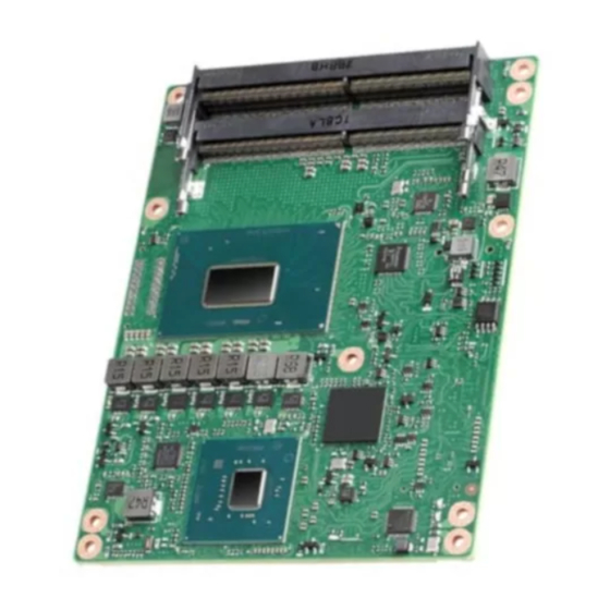
Page 24: Board Information
Board Information The figures below show the location of the main chips on the SOM-5899 Computer- on-Module. When designing customized boards, take care of positioning to avoid contact with thermal solutions and other mechanical issues for optimal performance. Smart Fan... -
Page 25: Connector List
Wafer 2.0mm 3P 90D (M) DIP 2001-WR-03-LF W/Lock Pin Name Fan Tacho-Input Fan Out Mechanical Drawing For more detail regarding 2D/3D models, please visit the Advantech COM support service website: http://com.advantech.com. 59.95 40.55 30.15 Figure 2.3 Board Mechanical Drawing – Front... -
Page 26: Figure 2.4 Board Mechanical Drawing - Rear
Figure 2.4 Board Mechanical Drawing – Rear 9.20 Figure 2.5 Board Mechanical Drawing – Side SOM-5899 User Manual... -
Page 27: Assembly Drawing
These figures demonstrate the assembly order from the thermal module and COM module to carrier board. Semi-cooler Heat Spreader SOM-5899 SOM-DB5830 Figure 2.6 Assembly Drawing There are 5 reserved screw holes for SOM-5899 to be pre-assembled with the heat spreader. SOM-5899 User Manual... -
Page 28: Assembly Drawing
Please consider the CPU and chip height tolerance when designing your thermal solution. Figure 2.7 CPU 6C + GT2 Height and Tolerance (For all other SKUs please contact Advantech sales or FAE for more details) Figure 2.8 PCH Height and Tolerance ... -
Page 29: Chapter 3 Ami Bios
Chapter AMI BIOS This chapter gives BIOS setup information for the SOM-5899 CPU Computer-on Module Sections include: Introduction Entering Setup Hot/Operation Key Exit BIOS Setup Utility... -
Page 30: Starting
Starting The SOM-5899 BIOS is stored into a flash ROM which can be inserted into a BIOS socket on the board. With the BIOS Setup program, users can modify BIOS settings and control various system features. This chapter describes the basic navigation of the SOM-5899 BIOS setup screens. -
Page 31: Main Setup
Enter Entering submenu or display option items. SOM-5899 BIOS has a built-in Setup program that allows users to modify the basic system configuration. This information is stored in flash ROM so it retains the Setup information when the power is turned off. - Page 32 Core Version No Option sion. Displays this BIOS supporting industry stan- Compliancy No Option dards compliance. Displays the project version of Advantech Project Version No Option projects. Build Date and Time No Option Displays this BIOS build date and time.
-
Page 33: Advanced Bios Features Setup
3.1.2 Advanced BIOS Features Setup Select the Advanced tab from the SOM-5899 setup screen to enter the Advanced BIOS Setup screen. Users can select any item in the left frame of the screen, such as CPU Configuration, to go to the sub menu for that item. Users can display an Advanced BIOS Setup options by highlighting them using the <Arrow>... - Page 34 This variable determines if we enable the ACPI Lower Power S0 Idle Capabil- Disabled ity (Mutually exclusive with Smart con- Low Power S0 Idle Capability Enabled nect). While this is enabled, it also disables the 8254 timer for SLP_S0 sup- port. SOM-5899 User Manual...
- Page 35 Enabled for Windows XP and Linux (OS optimized for Hyper-Threading Technol- Disabled Hyper-Threading ogy) and Disabled for other OS (OS not Enabled optimized for Hyper-Threading Technol- ogy). Disabled Enable/Disable AES (Advanced Encryp- Enabled tion Standard) SOM-5899 User Manual...
- Page 36 3.1.2.3 Power & Performance Feature Options Description CPU - Power Management Control CPU - Power Management Control <Sub Menu> Options GT - Power Management Control GT - Power Management Control <Sub Menu> Options SOM-5899 User Manual...
- Page 37 Turbo Performance Intel(R) Disabled Allows more than two frequency ranges to Speed- Enabled be supported. Step(tm) Disabled Enable/Disable processor Turbo Mode Turbo Mode Enabled (requires Intel Speed Step or Intel SOM-5899 User Manual...
- Page 38 GT - Power Management Control Feature Options Description RC6(Render Disabled Check to enable render standby sup- Standby) Enabled port. SOM-5899 User Manual...
- Page 39 When Disabled ME will not be unconfig- ME Unconfig on RTC Clear Enabled ured on RTC Clear Configure Management Engine Tech- Firmware Update Configuration <Sub Menu> nology Parameters Check to enable render standby sup- PTT Configuration <Sub Menu> port. SOM-5899 User Manual...
- Page 40 AMT Configuration Feature Options Description Disabled Enable/Disable Alert Standard Format ASF support Enabled support. Disabled Enable/Disable of AMT USB Provi- USB Provisioning of AMT Enabled sioning. SOM-5899 User Manual...
- Page 41 Network Access must be activated first from MEBx Setup. OEM defined timeout for MPS connec- tion to be established. 0 - use the default timeout value of 60 CIRA Timeout No Option seconds. 255 - MEBx waits until the connection succeeds SOM-5899 User Manual...
- Page 42 PET Events. Disabled WatchDog Enable/Disable WatchDog Timer Enabled OS Timer No Option Set OS watchdog timer. BIOS Timer No Option Set BIOS watchdog timer. Disabled Adds ASF Sensor Table into ASF! ASF Sensors Table Enabled ACPI Table SOM-5899 User Manual...
- Page 43 Secure Erase Configuration Feature Options Description Simulated Secure Erase Configuration Secure Erase configuration menu Real Disabled Force Secure Erase Force Secure Erase on next boot Enabled SOM-5899 User Manual...
- Page 44 ME uncon- figuration. Disabled OEMFlag Bit 14: MEBx OEM Debug Menu Enable Enabled Enable OEM debug menu in MEBx. OEMFlag Bit 15: Disabled Unconfigure ME Unconfigure ME with resetting Enabled MEBx password to default. SOM-5899 User Manual...
- Page 45 MEBx Resolution Settings Feature Options Description Auto Non-UI Mode Resolution 80x25 Resolution for non-UI text mode. 100x31 Auto UI Mode Resolution 80x25 Resolution for UI text mode. 100x31 Auto 640x480 Graphics Mode Resolution Resolution for graphics mode. 800x600 1024x768 SOM-5899 User Manual...
- Page 46 Firmware Update Configuration Feature Options Description Disabled Enable/Disable Me FW Image Re- Me FW Image Re-Flash Enabled Flash function. SOM-5899 User Manual...
- Page 47 Selects TPM device: PTT or dTPM. PTT - Enables PTT in SkuMgr dTPM 1.2 - dTPM TPM Device Selection Disables PTT in SkuMgr Warning ! PTT/ dTPM will be disabled and all data saved on it will be lost. SOM-5899 User Manual...
- Page 48 3.1.2.5 Trusted Computing Feature Options Description Enables or Disables BIOS support for Disabled security device. O.S. will not show Security Device Support Enabled Security Device. TCG EFI protocol and INT1A interface will not be available. SOM-5899 User Manual...
- Page 49 Select the highest ACPI sleep state the Suspend Disabled S3 (Sus- ACPI Sleep State system will enter when the SUSPEND pend to RAM) button is pressed. Disabled S3 Video Repost Enable or Disable S3 Video Repost Enabled SOM-5899 User Manual...
- Page 50 Power Saving Mode Select Power Saving Mode Deep Sleep Serial Port 1 Config- <Sub Menu> Set Parameters of Serial Port 1 (COMA) uration Serial Port 2 Config- <Sub Menu> Set Parameters of Serial Port 2 (COMB) uration SOM-5899 User Manual...
- Page 51 Serial Port Enable or Disable Serial Port (COM) Enabled Device Settings No Option Device settings for Super IO Device IO=3F8h; IRQ=4; IO=2F8h; IRQ=4; Select an optimal setting for Super IO Change Settings IO=3E8h; IRQ=4; Device IO=2E8h; IRQ=4; SOM-5899 User Manual...
- Page 52 Serial Port Enable or Disable Serial Port (COM) Enabled Device Settings No Option Device settings for Super IO Device IO=3F8h; IRQ=3; Change Settings IO=2F8h; IRQ=3; Select an optimal settings for Super IO IO=3E8h; IRQ=3; Device IO=2E8h; IRQ=3; SOM-5899 User Manual...
- Page 53 No option Shows the current status Carrier Board FAN No option Shows the current status +12V No option Shows the current status + 5V No option Shows the current status VBAT No option Shows the current status SOM-5899 User Manual...
- Page 54 ANSI: Extended ASCII char set. VT100 VT100: ASCII char set VT100+ Terminal Type VT100+: Extends VT100 to support VT-UTF8 color, function keys, etc. ANSI VT-UTF8: Uses UTF8 encoding to map Unicode chars onto 1 or more bytes. SOM-5899 User Manual...
- Page 55 With this mode enabled only text will be Recorder Mode Enabled sent. This is to capture Terminal data. Disabled Enables or disables extended terminal Resolution 100x31 Enabled resolution VT100 LINUX XTERMR6 Select FunctionKey and KeyPad on Putty KeyPad Putty. ESCN VT400 SOM-5899 User Manual...
- Page 56 Always Enable. Console Redirection Settings (EMS) Feature Options Description Microsoft Windows Emergency COM1 Management Services (EMS) COM2 Out-of-Band Mgmt Port allows for remote management of COM2(Pci Bus0,Dev0,Func0) a Windows Server OS through a (Disabled) serial port. SOM-5899 User Manual...
- Page 57 Stop bits indicate the end of a serial data packet. (A start bit indi- cates the beginning). The standard Stop Bits No Option setting is 1 stop bit. Communica- tion with slow devices may require more than 1 stop bit. SOM-5899 User Manual...
- Page 58 Host Con- Auto Device power-up delay troller. 'Auto' uses default value: for a Root Manual port it is 100 ms, for a Hub port the delay is taken from Hub descriptor. SOM-5899 User Manual...
- Page 59 3.1.2.10 Network Stack Configuration SOM-5899 User Manual...
- Page 60 PXE boot. Use either +/- or numeric keys to set the value. Number of times the presence of media Media detect count 1~50 will be checked. Use either +/- or numeric keys to set the value. 3.1.2.11 CSM Configuration SOM-5899 User Manual...
- Page 61 CompatibilitySmm, as an addition to features pro- vided by the UEFI SMM. This is optional and highly chipset- and plat- form-specific. An example of such a legacy SMM functionality is providing USB legacy support for keyboard and mouse, by emulating their classic PS/2counterparts. SOM-5899 User Manual...
- Page 62 3.1.2.12 NVMe Configuration NVMe Device Options Settings SOM-5899 User Manual...
-
Page 63: Chipset
3.1.3 Chipset Select the Chipset tab from the SOM-5899 setup screen to enter the Chipset BIOS Setup screen. You can display a Chipset BIOS Setup option by highlighting it using the <Arrow> keys. All Plug and Play BIOS Setup options are described in this sec- tion. - Page 64 PEG Port <Sub Menu> PEG Port Options Configuration Disabled VT-d VT-d capability Enabled Enable/Disable above 4GB Memory- Above 4GB MappedIO BIOS assignment. Disabled MMIO BIOS This is enabled automatically when Enabled assignment Aperture Size is set to 2048MB. SOM-5899 User Manual...
- Page 65 2.75 GB Maximum Value of TOLUD. Dynamic 2.5 GB assignment would adjust TOLUD Max TOLUD 2.25 GB automatically based on largest MMIO 2 GB length of installed graphic controller 1.75 GB 1.5 GB 1.25 GB 1 GB SOM-5899 User Manual...
- Page 66 PEG Eval: DGPU Power Enable = ActiveHigh Auto Internal Keep IGFX enabled based on the Disabled Graphics setup options. Enabled GTT Size Select the GTT Size 128MB 256MB Aperture Size 512MB Select the Aperture Size 1024MB 2048MB SOM-5899 User Manual...
- Page 67 Internal Graphics Device. 128M Select DVMT5.0 Total Graphic Mem- DVMT Total 256M ory size used by the Internal Graphics Gfx Mem Device. Disabled PM Support Enable/Disable PM Support Enabled Disabled PAVP Enable Enable/Disable PAVP Enabled LCD Control SOM-5899 User Manual...
- Page 68 1600x1200 appropriate setup item. 1920x1080 Customize Disabled Intel(R) Ultrabook Event Support PEG Port Configuration Feature Options Description IUER Slate Disabled Enable/Disable IUER Slate Function- Enable Enabled ality IUER Dock Disabled Enable/Disable IUER Dock Function- Enable Enabled ality SOM-5899 User Manual...
- Page 69 0.1x Select the scale used for the Slot Power Scale 0.01x Limit Value. 0.001x Set the physical slot number attached to PEG0 Physical Slot Num- 0~8191 be globally unique within the chassis Val- ues 0-8191 PEG 0:1:1 SOM-5899 User Manual...
- Page 70 PEG Port Feature Configuration ration Enabled: PCIe ASPM will be pro- Program PCIe ASPM after grammed after OpROM. OpROM Disabled: PCIe ASPM will be pro- grammed before OpROM. PCIe Spread Spectrum Allows disableing Spread Spectrum Clocking Clocking for compliance testing SOM-5899 User Manual...
- Page 71 PEG Port Feature Configuration Feature Options Description Disabled Detect Non-Compliance PCI Express Detect Non-Compliance Device Enabled Device in PEG SOM-5899 User Manual...
- Page 72 Wake on LAN Enable Enabled system. Quiet Serial IRQ Mode Config Serial IRQ Mode. Continuous S0 State Specify what state to go to when power is re- State After G3 S5 State applied after a power failure (G3 state). SOM-5899 User Manual...
- Page 73 PCH PCIe Port Config 2 Config PCH PCIe Lane 4~7 setting Disabled The control of Active State Power DMI Link ASPM Control Management of the DMI Link. L0sL1 Auto PCI Express Root Port 0~7 <Sub Menu> PCI Express Root Port Settings. SOM-5899 User Manual...
- Page 74 Force L0s - Force all links to L0s State ASPM AUTO - BIOS auto configure L0sL1 DISABLE - Disables ASPM AUto Disabled PCI Express Hot Plug Enable/Dis- Hot Plug Enabled able. Auto Gen1 PCIe Speed Configure PCIe Speed Gen2 Gen3 SOM-5899 User Manual...
- Page 75 SATA And RST Configuration SOM-5899 User Manual...
- Page 76 [0,1,2,3,5] DevSlp. For DevSlp to work, both hard drive and SATA SATA Port Disabled port need to support DevSlp func- [0,1,2,3,5] DevSlp Enabled tion, otherwise an unexpected behavior might happen. Please check board design before enabling it. SOM-5899 User Manual...
- Page 77 If enabled, indicates that the HDD HDD Unlock Enabled password unlock in the OS is enabled. If enabled, indicates that the LED/ Disabled LED Locate SGPIO hardware is attached and ping Enabled to locate feature is enabled on the OS. SOM-5899 User Manual...
- Page 78 USB Configuration Feature Options Description Option to enable Compliance Mode. Disabled Default is to disable Compliance Mode. XHCI Compliance Mode Enabled Change to enabled for Compliance Mode testing. SOM-5899 User Manual...
- Page 79 Enable will lock bytes 38h-3Fh in the RTC Memory Lock Enabled lower/upper 128-byte bank of RTC RAM Enable/Disable the PCH BIOS Lock Disabled BIOS Lock Enable feature. Required to be enabled Enabled to ensure SMM protection of flash. SOM-5899 User Manual...
- Page 80 HD Audio Configuration Feature Options Description Disabled HD Audio HD Audio Subsystem Configuration Settings Enabled SOM-5899 User Manual...
- Page 81 This is needed to allow PCI enumerator access func- Disabled I2C0 Controller tions above 0 in a multifunction Enabled device. The following devices depend on each other: I2C0 and I2C1,2,3 UART0 and UART1,SPI0,1 UART2 and I2C4,5 SOM-5899 User Manual...
- Page 82 SCS Configuration Feature Options Description Disabled Enable or Disable SCS SDHC 3.0 Con- SDCard 3.0 Controller Enabled troller SOM-5899 User Manual...
-
Page 83: Security
3.1.4 Security Select Security tab from the SOM-5899 main BIOS setup menu. All security setup options, such as password protection are described in this section. To access the sub menu for the following items, select the item and press <Enter>:... - Page 84 Note! Please keep your password safe. For security reasons, the BIOS pass- word can't be reset by clearing CMOS. If you forget your password, please contact Advantech for technical support. 3.1.4.1 Secure Boot Feature Options Description Disabled Secure Boot Set Administrator Password...
- Page 85 PE image into Authorized Signature Database (db) Device Guard ready system must not list 'Microsoft UEFI CA' Certifi- Remove 'UEFI CA' from DB cate in Authorized Signature data- base (db) Restore DB variable to factory Restore DB defaults defaults SOM-5899 User Manual...
- Page 86 One of Secure Boot variable Append Delete Details Export Forbidden Signatures Update One of Secure Boot variable Append Delete Update One of Secure Boot variable Authorized TimeStamps Append Update OsRecovery Signatures One of Secure Boot variable Append SOM-5899 User Manual...
-
Page 87: Boot Settings
OS and Post. If Auto, only install Legacy OpRom VGA Sup- Auto with Legacy OS and logo would NOT port (Note) EFI Driver be shown during post. Efi driver will still be installed with EFI OS. SOM-5899 User Manual... -
Page 88: Save & Exit
If Disabled, NetWork Stack Driver will Support Enabled be skipped. (Note) Redirection Disabled If disable, Redirection function will be Support Enabled disabled. (Note) Note! These items will be hidden when "Fast Boot" is disabled. 3.1.6 Save & Exit SOM-5899 User Manual... - Page 89 Default Options Restore/Load Default values for all the Restore Defaults setup options. Save the changes done so far as User Save as User Defaults Defaults. Restore the User Defaults to all the Restore User Defaults setup options. SOM-5899 User Manual...
- Page 90 SOM-5899 User Manual...
-
Page 91: Chapter 4 S/W Introduction & Installation
Chapter S/W Introduction & Installation S/W Introduction Driver Installation Advantech iManager... -
Page 92: S/W Introduction
Embedded features easily integrate, speed up the development schedule, and pro- vide the customer’s with software continuity while upgrading hardware. For more details regarding how to use the APIs and utilities, please refer to the Advantech iManager 2.0 Software API User Manual. - Page 93 SOM-5899 User Manual...
- Page 94 SOM-5899 User Manual...
-
Page 95: Appendix A Pin Assignment
Appendix Pin Assignment This appendix gives you the infor- mation about the hardware pin assignment of the SOM-5899 CPU System on Module Sections include: SOM-5899 Type 6 Pin Assignment... -
Page 96: Som-5899 Type 6 Pin Assignment
This section gives SOM-5899 pin assignment on the COM Express connector, which is compliant with COMR.0 R3.0 Type 6 pin-out definitions. For more details about how to use these pins and get design reference, please contact Advantech for the design guide, checklist, reference schematic, and other hardware/software support. - Page 97 LVDS_B0- LVDS_A1+ LVDS_B1+ LVDS_A1- LVDS_B1- LVDS_A2+ LVDS_B2+ LVDS_A2- LVDS_B2- LVDS_VDD_EN LVDS_B3+ LVDS_A3+ LVDS_B3- LVDS_A3- LVDS_BKLT_EN GND (FIXED) GND (FIXED) LVDS_A_CK+ LVDS_B_CK+ LVDS_A_CK- LVDS_B_CK- LVDS_I2C_CK LVDS_BKLT_CTRL LVDS_I2C_DAT VCC_5V_SBY GPI3 VCC_5V_SBY N/A (Note 1) VCC_5V_SBY eDP_HPD VCC_5V_SBY PCIE_CLK_REF+ BIOS_DIS1# SOM-5899 User Manual...
- Page 98 A107 VCC_12V B107 VCC_12V A108 VCC_12V B108 VCC_12V A109 VCC_12V B109 VCC_12V A110 GND (FIXED) B110 GND (FIXED) SOM-5899 Row C,D GND (FIXED) GND (FIXED) USB_SSRX0- USB_SSTX0- USB_SSRX0+ USB_SSTX0+ USB_SSRX1- USB_SSTX1- USB_SSRX1+ USB_SSTX1+ USB_SSRX2- USB_SSTX2- USB_SSRX2+ USB_SSTX2+ GND (FIXED) GND (FIXED)
- Page 99 PEG_TX0- PEG_LANE_RV# PEG_RX1+ PEG_TX1+ PEG_RX1- PEG_TX1- TYPE2# (GND) PEG_RX2+ PEG_TX2+ PEG_RX2- PEG_TX2- GND (FIXED) GND (FIXED) PEG_RX3+ PEG_TX3+ PEG_RX3- PEG_TX3- PEG_RX4+ PEG_TX4+ PEG_RX4- PEG_TX4- RAPID_SHUTDOWN PEG_RX5+ PEG_TX5+ PEG_RX5- PEG_TX5- GND (FIXED) GND (FIXED) PEG_RX6+ PEG_TX6+ PEG_RX6- PEG_TX6- SOM-5899 User Manual...
- Page 100 PEG_TX15+ C102 PEG_RX15- D102 PEG_TX15- C103 D103 C104 VCC_12V D104 VCC_12V C105 VCC_12V D105 VCC_12V C106 VCC_12V D106 VCC_12V C107 VCC_12V D107 VCC_12V C108 VCC_12V D108 VCC_12V C109 VCC_12V D109 VCC_12V C110 GND (FIXED) D110 GND (FIXED) SOM-5899 User Manual...
-
Page 101: Appendix B Watchdog Timer
Appendix Watchdog Timer This appendix gives you the infor- mation about the watchdog timer programming on the SOM-5899 CPU System on Module Sections include: Watchdog Timer Programming... -
Page 102: Programming The Watchdog Timer
BIOS, and then sets to EC. Only Win8.1 and Win10 support it. Other OS will still use the IRQ number from BIOS setting as usual. For details, please refer to the iManager & Software API User Manual. SOM-5899 User Manual... -
Page 103: Appendix C Programming Gpio
Appendix Programming GPIO This Appendix gives the illustra- tion of the General Purpose Input and Output pin setting. Sections include: System I/O ports... -
Page 104: Gpio Register
GPIO Register GPIO Byte Mapping H/W Pin Name BIT0 GPO0 BIT1 GPO1 BIT2 GPO2 BIT3 GPO3 BIT4 GPI0 BIT5 GPI1 BIT6 GPI2 BIT7 GPI3 For details, please refer to the iManager & Software API User Manual. SOM-5899 User Manual... -
Page 105: Appendix D System Assignments
Appendix System Assignments This appendix gives you the infor- mation about the system resource allocation on the SOM-5899 CPU System on Module Sections include: System I/O ports DMA Channel Assignments Interrupt Assignments 1 MB Memory Map... -
Page 106: System I/O Ports
Programmable interrupt controller 00BC-00BD Programmable interrupt controller 00F0-00F0 Numeric data processor 0200-027F Motherboard resources 0280-028F Motherboard resources 0290-029F Motherboard resources 0299-029A Motherboard resources 029E-02AD Motherboard resources 02A0-02BF Motherboard resources 02C0-02DF Motherboard resources 02F0-02F7 Motherboard resources 02F8-02FF Communications Port (COM2) SOM-5899 User Manual... - Page 107 Motherboard resources 2000-20FE Motherboard resources 3000-303F Intel(R) UHD Graphics 630 3060-307F Standard SATA AHCI Controller 3080-3083 Standard SATA AHCI Controller 3090-3097 Standard SATA AHCI Controller EFA0-EFBF Intel(R) SMBus - A323 FFF8-FFFF Intel(R) Active Management Technology - SOL (COM3) SOM-5899 User Manual...
-
Page 108: Interrupt Assignments
Intel(R) Ethernet Connection (7) I219-LM IRQ 0xFFFFFFFB (-5) Intel(R) Management Engine Interface IRQ 0xFFFFFFFC(-4) Intel(R) USB 3.1 eXtensible Host Controller - 1.10 (Microsoft) IRQ 0xFFFFFFFD (-3) Intel(R) UHD Graphics 630 IRQ 0xFFFFFFFE (-2) Standard SATA AHCI Controller SOM-5899 User Manual... -
Page 109: 1St Mb Memory Map
Intel(R) Serial IO GPIO host Controller - INT3450 0xFD6BFFFF 0xFD6C0000- Motherboard resources 0xFD6CFFFF 0xFD6D0000- Intel(R) Serial IO GPIO host Controller - INT3450 0xFD6DFFFF 0xFD6E0000- Intel(R) Serial IO GPIO host Controller - INT3450 0xFD6EFFFF 0xFD6F0000- Motherboard resources 0xFDFFFFFF 0xFE000000- Motherboard resources 0xFE01FFFF SOM-5899 User Manual... - Page 110 High precision event timer 0xFED003FF 0xFED10000- Motherboard resources 0xFED17FFF 0xFED18000- Motherboard resources 0xFED18FFF 0xFED19000- Motherboard resources 0xFED19FFF 0xFED20000- Motherboard resources 0xFED3FFFF 0xFED45000- Motherboard resources 0xFED8FFFF 0xFED90000- Motherboard resources 0xFED93FFF 0xFEE00000- Motherboard resources 0xFEEFFFFF 0xFF000000- Motherboard resources 0xFFFFFFFFF SOM-5899 User Manual...
- Page 111 SOM-5899 User Manual...
- Page 112 No part of this publication may be reproduced in any form or by any means, electronic, photocopying, recording or otherwise, without prior written permis- sion of the publisher. All brand and product names are trademarks or registered trademarks of their respective companies. © Advantech Co., Ltd. 2018...
Need help?
Do you have a question about the SOM-5899 and is the answer not in the manual?
Questions and answers