Table of Contents
Advertisement
Quick Links
IPMI-1000
IPMI module, AST2300 chipset
Startup Manual
Packing List
Before you begin installing your card, please make sure that
the following items have been shipped:
1. IPMI-1000 module x 1
2. Startup manual x 1
3. Screw x 2
4. Warranty Card x 1
5. VGA cable x 1
If any of these items are missing or damaged, please con-
tact your distributor or sales representative immediately.
For more information on this and other Advantech
products, please visit our website at:
http://www.advantech.com
http://www.advantech.com/eplatform
For technical support and service, please visit our
support website at:
http://support.advantech.com
This manual is for the IPMI-1000 Series.
Part No. 2006IPM100
Print in China
PN: 20061IPM100
P/N: 19350304A0
P/N: 2190000902
P/N: 1700020805
1st Edition
October 2012
Specifications
General Features
• Out of band (OS independent)
• User management
• Remote control
• System health
• Maintenance
SBC Support List
PPCE-7127G2-00A1E
PCE-5126WG2-00A1E
Note: For more SBC support list, please visit our website.
Mechanical and Environmental
• Dimensions: 68 mm x 31.5 mm
• Power supply type: 5 VSB
• Power requirements: 5 VSB @ 55mA
• Operating temperature: 0 ~ 60° C
• Operating humidity: 60° C @ 85% RH, Non-Condensing
• Storage temperature: -40 ~ 85° C
• Storage humidity: 60° C @ 95% RH, Non-Condensing
• Weight: 0.48 kg
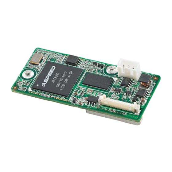
Connectors
There are four connectors on the module and one of them
is used to connect with SBC. The below table lists the func-
tions of these connectors.
Connectors
Label
Function
BMC1
IPMI connector
VGA1
VGA1 connector
MRCROSD1
Local media device
IPMB
Reserved
IPMI-1000 Startup Manual 1
Advertisement
Table of Contents

Related Manuals for Advantech IPMI-1000


Summary of Contents for Advantech IPMI-1000
- Page 1 SBC. The below table lists the func- tions of these connectors. Connectors Label Function BMC1 IPMI connector For more information on this and other Advantech VGA1 VGA1 connector products, please visit our website at: http://www.advantech.com MRCROSD1 Local media device http://www.advantech.com/eplatform...
- Page 2 Figure 3: Assembling module Figure 6: BMC network configuration setting Note: At first time initialing IPMI-1000, it may take around 30~40 seconds before posting BIOS. When F/W is ready, the LED light of module will be flashing.
- Page 3 Board Layout and Dimension Figure 7: IPMI-1000 Top side Board Layout Figure 8: IPMI-1000 Bottom side Board Layout IPMI-1000 Startup Manual 3...
- Page 5 No part of this manual may be reproduced, copied, translated or transmitted in any form or by any means without the prior written permission of Advantech Co., Ltd. Information provided in this manual is intended to be accurate and reliable. How- ever, Advantech Co., Ltd.
- Page 6 It should be free of marks and scratches and in perfect working order upon receipt. As you unpack the IPMI-1000, check it for signs of ship- ping damage. (For example, damaged box, scratches, dents, etc.) If it is damaged or it fails to meet the specifications, notify our service department or your local sales representative immediately.
- Page 7 IPMI-1000 User Manual...
-
Page 8: Table Of Contents
Introduction ....................2 Specifications .................... 2 Connectors....................2 Table 1.1: Connectors ..............2 Board Layout: Connector Locations............3 Figure 1.1 IPMI-1000 Top Side Board Layout ......3 Figure 1.2 IPMI-1000 Bottom Side Board Layout ......3 Chapter Setup.............5 Introduction ....................6 H/W setting.................... - Page 9 Figure 3.27Maintenance - Firmware Update Page..... 27 Figure 3.28Maintenance - Restore Factory Defaults Page ..27 Figure 3.29Maintenance - System Administrator Page ....27 Log Out ....................27 Appendix A Port Usage ......... 29 Port Usage ....................30 IPMI-1000 User Manual...
-
Page 10: Chapter 1 Hardware Configuration
Chapter Hardware Configuration... -
Page 11: Introduction
Introduction IPMI-1000 is a proprietary form-factor module which is designed with Aspeed AST2300 for remote management purposes. Also, IPMI-1000 is fully compliant with IPMI 2.0 specification. Specifications Chipset AST2300 Compliant with IPMI 2.0 VGA output KVM over IP... -
Page 12: Board Layout: Connector Locations
Board Layout: Connector Locations Figure 1.1 IPMI-1000 Top Side Board Layout Figure 1.2 IPMI-1000 Bottom Side Board Layout IPMI-1000 User Manual... - Page 13 IPMI-1000 User Manual...
-
Page 14: Chapter 2 Setup
Chapter Setup... -
Page 15: Introduction
Please follow the H/W, BIOS & LAN setting shown below to properly setup the IPMI- 1000. H/W setting The IPMI-1000 module should be carefully placed on BMC1 (2 x 50 connector), Once BMC is active, an LED indicator will be blinking. Figure 2.1 Assembling Module Align the screw holes, and securely fasten with the screws. -
Page 16: Bios Settings
BIOS Settings Once IPMI-1000 module has been connected to SBC, the BIOS will show a "Server Mgmt" section automatically. Server Mgmt is used to modify the settings of IPMI- 1000. 2.3.1 BMC Support Default is [Enable]; Set [Disable] if you don't need the BMC function. - Page 17 Figure 2.3 Example of PCE-5126WG2 IPMI-1000 User Manual...
-
Page 18: Chapter 3 Graphic User Interface (Gui)
Chapter Graphic User Interface (GUI) -
Page 19: Login Page
Login Page To Login to the Graphics User Interface (GUI) of the IPMI-1000, open an Internet browser and connect to the IP address for the IPMI-1000. The login page will show as on the following screen. Default user name and password... -
Page 20: Dashboard
Click Launch to launch the console redirection and to manage the remote server. The console preview of the remote server using java application can be viewed under this section. Click on Refresh button to reload the console preview. IPMI-1000 User Manual... -
Page 21: Sensor Monitoring
Status and Current Reading will be displayed. Live Widget: Click On or Off makes the widget appear or disappear. Gives a dynamic representation of the reading of sensor. Figure 3.3 Server Health - Sensor Readings Page IPMI-1000 User Manual... -
Page 22: Event Log
Figure 3.4 Server Health - Event Log Page 3.3.3 System & Audit Log Displays all system and audit events. System Log: To view all system events. Audit Log: To view all audit events. Figure 3.5 Server Health - System & Audit Page IPMI-1000 User Manual... -
Page 23: Configuration
Default Time out 120 seconds; Range from 15 to 300 seconds. Domain Controller Server Addresses: Configure IP addresses in these areas. Note! At least one Domain Controller Server Address must be configured. Figure 3.6 Configuration - Active Directory Page IPMI-1000 User Manual... -
Page 24: Dns
– DNS Server Settings: Choose either “Manual” or “available LAN interface”. – Preferred DNS Server: Configure the DNS server v6 address. – Alternate DNS Server: Configure the DNS server v6 address. Figure 3.7 Configuration - DNS Page IPMI-1000 User Manual... -
Page 25: Ldap
Local Media support under Configuration -> Virtual Media. Note! Only administrator can change local media. Each image type supports one image upload. Maximum upload size is 8 MB. Figure 3.9 Configuration - Local Media Page IPMI-1000 User Manual... -
Page 26: Mouse Mode
NCSI Interface: Lists the interface name in list box. Channel Number: Lists the channel number of the selected interface. Package ID: Lists the package id of the selected interface. Figure 3.11 Configuration - NCSI Page IPMI-1000 User Manual... -
Page 27: Network
Enable/disable the VLAN support for selected interface. – VLAN ID: Identification for VLAN configuration. (Ranges from 1 to 4095) – VLAN Priority: Priority for VLAN configuration. (Ranges from 1 to 7; 7 is highest priority) Figure 3.12 Configuration - Network Page IPMI-1000 User Manual... -
Page 28: Ntp
Synchronize Date and Time automatically with the NTP Server. Figure 3.13 Configuration - NTP page 3.4.9 PAM Order Used to configure the Pluggable Authentication Module (PAM) ordering for user authentication in to the BMC. Figure 3.14 Configuration - PAM Order Page IPMI-1000 User Manual... -
Page 29: Pef
An email will be sent to the configured email address if a severity event occurs; it will contain a subject in the subject field and the message field con- tent of the event will be in the email body. IPMI-1000 User Manual... -
Page 30: Radius
Default is 3 seconds and ranges from 3 to 300. Server Address: The IP address of RADIUS server. Secret: The Authentication Secret for RADIUS server. Note! This field will not allow more than 31 characters. IPMI-1000 User Manual... -
Page 31: Remote Session
Two types of VM attach mode are available Figure 3.17 Configuration - Remote Session Page 3.4.13 Services This page displays the basic information about services running in the BMC. Only Administrator can modify the service. Figure 3.18 Configuration - Services Page IPMI-1000 User Manual... -
Page 32: Smtp
Figure 3.19 Configuration - SMTP Page 3.4.15 System and Audit Log System and Audit log page displays a list of system and audit events that have been logged on this device. Figure 3.20 Configuration - System and Audit Log Page IPMI-1000 User Manual... -
Page 33: Users
Hard disk devices: The number of hard disk devices that support Virtual Media redirection. Local Media Support: Enable or disable the local media support for Virtual Media redirection. Figure 3.22 Configuration - Virtual Media Page IPMI-1000 User Manual... -
Page 34: Remote Control
– Power Cycle Server: This option will first power off, and then reboot the system (cold boot). – Perform Action: Click this option to perform the selected operation. Figure 3.24 Remote Control - Server Power Control Page IPMI-1000 User Manual... -
Page 35: Auto Video Recording
A maximum of only 2 video files can be recorded and available for access, with each recording limited to 5.5MB or 20 seconds whichever occurs first. Further event occurrences will be ignored and no recording will happen, until at least one video file is deleted. IPMI-1000 User Manual... -
Page 36: Maintenance
System Administrator: Used to configure the System Administrator settings. Figure 3.29 Maintenance - System Administrator Page Log Out To log out of the GUI, click the logout link on the top right corner of the screen. IPMI-1000 User Manual... - Page 37 IPMI-1000 User Manual...
-
Page 38: Appendix A Port Usage
Appendix Port Usage... -
Page 39: Port Usage
KVM server (adviser) To accept secure (SSL based) KVM redirection connections IPMI LAN interface 1900 uPnP discovery Used for uPnP based BMC discovery 50000 uPnP discovery Used for uPnP based BMC discovery WSMAN Event daemon’s listening port 5988 SFCB (WSMAN) WSMAN related SLPD Service Locator IPMI-1000 User Manual... - Page 40 IPMI-1000 User Manual...
Need help?
Do you have a question about the IPMI-1000 and is the answer not in the manual?
Questions and answers