Table of Contents
Advertisement
Quick Links
Advertisement
Table of Contents

Related Manuals for Advantech B+B SmartWorx IE-iMcV-2xLIM


Summary of Contents for Advantech B+B SmartWorx IE-iMcV-2xLIM
- Page 1 IE-iMcV-2xLIM USER MANUAL...
- Page 2 Advantech B+B SmartWorx - Americas 707 Dayton Road Ottawa, IL 61350 USA Phone 1 (815) 433-5100 Fax 1 (815) 433-5105 Advantech B+B SmartWorx - European Headquarters Westlink Commercial Park Oranmore, Co. Galway, Ireland Phone +353 91-792444 Fax +353 91-792445 www.advantech-bb.com...
-
Page 3: Table Of Contents
IE-iMcV-2xLIM TABLE OF CONTENTS FCC Radio Frequency Interference Statement ............ 3 About This Manual ....................3 About the IE-iMcV-2xLIM..................4 Configuration Instructions ..................4 Installing the IE-iMcV-2xLIM ................. 5 Managed Modules ....................5 Configuration Control & SNMP Management ............5 Unmanaged Modules ................... -
Page 4: Fcc Radio Frequency Interference Statement
IE-iMcV-2xLIM FCC RADIO FREQUENCY INTERFERENCE STATEMENT This equipment has been tested and found to comply with the limits for a Class B computing device, pursuant to Part 15 of the FCC Rules. These limits are designed to provide reasonable protection against harmful interference when the equipment is operated in a commercial environment. -
Page 5: About The Ie-Imcv-2Xlim
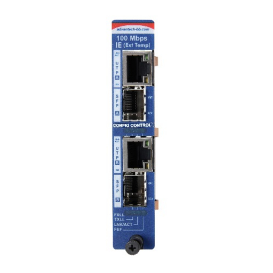
IE-iMcV-2xLIM ABOUT THE IE-IMCV-2XLIM The IE-iMcV-2xLIM, TX/SFP is a Fast Ethernet module that provides two conversions of 100Base-TX twisted pair to 100Base-FX/SX single-mode or multi- mode fiber. There are two sets of ports, each providing an RJ-45 (copper) to SFP (fiber) an SFP,155 Mbps, can be installed in the SFP port. -
Page 6: Installing The Ie-Imcv-2Xlim
IE-iMcV-2xLIM INSTALLING THE IE-IMCV-2XLIM The iMcV-2xLIM module installs in B+B SmartWorx’ SNMP manageable iMediaChassis series or in any MediaChassis. To install iMcV-2xLIM modules: Remove the blank bracket covering the slot where the module is to be installed by removing the screws on the outside edges of the bracket. Slide the modules into the chassis, via the card guides, until the module is seated securely in the connector. -
Page 7: Unmanaged Modules
IE-iMcV-2xLIM and the iMcV-module is configured by the chassis’ management module. If the SNMP management module is removed or fails, the iMcV-modules will revert back to the DIP Switch settings. When an iMcV-module configuration changes from the management module’s settings to DIP Switch settings, the traffic across the iMcV-module will be interrupted for a very short period of time. - Page 8 IE-iMcV-2xLIM IE-iMcV-2xLIM, TX/SFP and Configuration Control Default DIP Switch Feature Setting on S1 Auto Negotiation (AN) (Port A) FX LinkLoss (FXLL) (Port A) TX LinkLoss (TXLL) (Port A) Far End Fault (FEF) (Port A) Enable TX Port (Port A) Auto Negotiation (AN) (Port B) FX LinkLoss (FXLL) (Port B) TX LinkLoss (TXLL) (Port B) Far End Fault (FEF) (Port B)
-
Page 9: Fx Linkloss, Tx Linkloss, Link Fault Pass Through, Far End Fault
IE-iMcV-2xLIM FX LINKLOSS, TX LINKLOSS, LINK FAULT PASS- THROUGH, FAR END FAULT IE-iMcV-2xLIM, TX/SFP modules include the troubleshooting features: TXLL, FXLL, FEF and LFPT that help locate silent failures on a network. Before attempting to install the module(s), it is advised to understand how these features work and react to a specific network configuration. -
Page 10: Link Fault Pass Through (Lfpt)
IE-iMcV-2xLIM LINK FAULT PASS-THROUGH (LFPT) Link Fault Pass-Through (LFPT) is a troubleshooting feature that combines TX and FX LinkLoss from both the local and remote IE-iMcV-2xLIM, TX/SFP modules. LFPT is enabled by turning on both FX and TX LinkLoss on both modules. -
Page 11: Autocross Feature For Twisted Pair Connection
IE-iMcV-2xLIM End-to-End Connection Switch TX/FX Half-duplex Configure HDX manually. Auto Negotiation is Off. Full-duplex Configure FDX manually. Auto Negotiation is Off. Full-duplex Auto Negotiation is On. Auto Negotiation is On. Configure Auto Negotiation on an IE-iMcV-2xLIM, TX/SFP by adjusting the DIP Switch setting (for unmanaged modules) or via the management software. -
Page 12: Led Operation
IE-iMcV-2xLIM LED OPERATION The IE-iMcV-2xLIM, TX/SFP module features diagnostic LEDs that provide information on features and ports: FXLL Glows green when FX LinkLoss is enabled on the port. Blinks when a fault occurs on the fiber port and actively disables the copper port. TXLL Glows green when TX LinkLoss is enabled on the port. -
Page 13: Installation Troubleshooting
IE-iMcV-2xLIM INSTALLATION TROUBLESHOOTING • During installation, first test the fiber and twisted pair connections with all troubleshooting features disabled, then enable these features, if desired, just before final installation. This will reduce the features’ interference with testing. • To test a IE-iMcV-2xLIM, TX/SFP by itself, first have an appropriate fiber patch cable, then follow these steps to test: Connect the IE-iMcV-2xLIM, TX/SFP to the twisted pair device with a twisted pair cable. -
Page 14: Fiber Optic Cleaning Guidelines
IE-iMcV-2xLIM FIBER OPTIC CLEANING GUIDELINES Fiber Optic transmitters and receivers are extremely susceptible to contamination by particles of dirt or dust, which can obstruct the optic path and cause performance degradation. Good system performance requires clean optics and connector ferrules. Use fiber patch cords (or connectors, if you terminate your own fiber) only from a reputable supplier;... -
Page 15: Certifications
IE-iMcV-2xLIM CERTIFICATIONS The products described herein comply with the Council Directive on Electromagnetic Compatibility (2004/108/EC). Class 1 Laser product, Luokan 1 Laserlaite, Laser Klasse 1, Appareil A’Laser de Classe 1 European Directive 2002/96/EC (WEEE) requires that any equipment that bears this symbol on product or packaging must not be disposed of with unsorted municipal waste.
Need help?
Do you have a question about the B+B SmartWorx IE-iMcV-2xLIM and is the answer not in the manual?
Questions and answers