Table of Contents
Advertisement
Quick Links
INTRAC-305
Tel
Fax
e-mail
Website
The copyright of this document is vested in Advantech AMT Ltd and the document is issued in confidence
for the purpose only for which it is supplied. It must not be reproduced, in whole or in part, or used for
tendering or manufacturing purposes or disclosed to a third party except with the written consent of
Advantech AMT Ltd. Advantech AMT is a wholly owned operating company of Advantech Wireless Inc.
© 2011 Advantech Wireless
INTRAC™-305
INTELLIGENT TRACKING ANTENNA CONTROL UNIT
INSTALLATION & USER MANUAL
I
10 June 2008
Advantech AMT Ltd
39 Edison Road
Huntingdon
Cambs PE27 3LF
UK General Enquiries
International General Enquiries
UK 01480 357601
info.europe@advantechwireless.com
http://www.advantechwireless.com
.
INTRAC-305 MANUAL - ISSUE 3.2
3.2
SSUE
St Ives
England
01480 357600
+ 44 1480 357600
International + 44 1480 357601
PREFACE
Page i
Advertisement
Chapters
Table of Contents

Related Manuals for Advantech INTRAC INTRAC-305


Summary of Contents for Advantech INTRAC INTRAC-305
- Page 1 Website The copyright of this document is vested in Advantech AMT Ltd and the document is issued in confidence for the purpose only for which it is supplied. It must not be reproduced, in whole or in part, or used for tendering or manufacturing purposes or disclosed to a third party except with the written consent of Advantech AMT Ltd.
-
Page 2: Preface
How to install and set-up an INTRAC-305 system, includes information on the external connections to the INTRAC-305. Assistance in finding any faults which may arise. Warranty and repair service provided by Advantech AMT Ltd. INTRAC-305 MANUAL - ISSUE 3.2 INTRAC-305... - Page 3 INTRAC-305 PREFACE © 2011 Advantech Wireless INTRAC-305 MANUAL - ISSUE 3.2 Page iii...
-
Page 4: Table Of Contents
The IESS-412 Data NORAD Data ... Rapid Model Generation Program Track Reserve Model ... Clear Models ... Antenna Motion Limits ... Axes Position ... Tracking Signal ... Page iv INTRAC-305 MANUAL - ISSUE 3.2 INTRAC-305 PAGE © 2011 Advantech Wireless... -
Page 5: Contents
8. WARRANTY & REPAIR ... Warranty ... Repair Service Repairs not under Warranty APPENDICES ... See separate appendices index ... © 2011 Advantech Wireless Remote Port …………………………………………… Test Ports ………………………………………………. Serial Port RS422/423 Setting ...…. Serial Port Usage ...…. INTRAC-305 MANUAL - ISSUE 3.2... -
Page 6: Introducing The Intrac-305
No operator intervention or parameter setting is required when conditions or satellites are changed. INTRAC-305 MANUAL - ISSUE 3.2 INTRAC-305 © 2011 Advantech Wireless... - Page 7 PC based Remote Control and Monitoring Terminal. Existing Step Track or Program Track installations may be updated to INTRAC systems. Advantech AMT Ltd. have considerable experience of retro fitting INTRAC systems. INTRAC-305 MANUAL - ISSUE 3.2 INTRODUCTION...
- Page 8 Manually peak the antenna to maximize the beacon level and check that the beacon does not overload (24.9 dB displayed). Page viii is given below: INTRAC-305 MANUAL - ISSUE 3.2 INTRAC-305 Note displayed Az angle. © 2011 Advantech Wireless...
-
Page 9: Quick Start Guide
24 hours and check that system is maintaining track with displayed mode “Learning”. Soon after the 24 hour learning period the mode should change to “Tracking”, indicating that the system has successfully computed a full INTRAC model. © 2011 Advantech Wireless INTRAC-305 MANUAL - ISSUE 3.2 QUICK START GUIDE... -
Page 10: Safety
Pressing this switch will remove power from the antenna drive motors and the INTRAC will enter Standby mode. To restore drive the switch should be rotated clockwise (CW) and Auto Continue selected. INTRAC-305 MANUAL - Issue 3.2 INTRAC-305 © Advantech AMT Ltd... -
Page 11: Mechanical
INTRAC-305 MECHANICAL Mounting Important © 2011 Advantech Wireless Facilities exist at the Motor Drive Cabinet for the connection of external emergency stop switches. It is highly recommended that those fitted be of the latching type. The INTRAC-305 must not be mounted so that it is supported only by the front panel. -
Page 13: Specifications & Options
(drift) when power is removed from the motors must be less than the beamwidth. If the system does not conform to these requirements please consult with Advantech AMT Limited. INTRAC-305 MANUAL - Issue 3.2 of the Page 1... -
Page 14: Specification
The standard version of the INTRAC-305 is firmware configured for x1 resolvers. Firmware to enable the use of a x2 resolver for can be provided on request. INTRAC-305 MANUAL - Issue 3.2 INTRAC-305 Harowe 11BRCX-310-M-85V Clifton 11-BHM-19F/F776 Harrowe 11_BRCX-310-R-85V Clifton 11-BHW-46TK/F561 or F817 ©2011 Advantech Wireless... - Page 15 Operating Temperature Relative Humidity Power Country of Origin © 2011 Advantech Wireless SPECIFICATION & OPTIONS The indicated pointing angles can be electrically offset in all axes to an accuracy of 0.01 to compensate for angular mounting offset in the position encoders.
-
Page 16: Options
Pol resolver geared 1:1 to the polarisation tube. Firmware for a Pol resolver geared 2:1 to the polarisation tube is available if required. Note this is a INTRAC-305 MANUAL - Issue 3.2 INTRAC-305 RS422 Ribbon Link Cable Position Position J44 Rear J46 Rear ©2011 Advantech Wireless... - Page 17 Mount Type Resolver Type Stow Option Dual Redundant PSU © 2011 Advantech Wireless SPECIFICATION & OPTIONS firmware change and required the EPROM on the interface card to be changed. Two types of antenna mount may be used with the INTRAC.
- Page 18 SPECIFICATION & OPTIONS INTRAC-305 Deliberately blank Page 6 INTRAC-305 MANUAL - Issue 3.2 ©2011 Advantech Wireless...
-
Page 19: Operating The Intrac-305
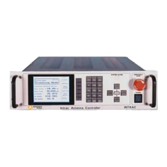
Numeric Keypad Manual Control Keys System Alarm Indicator Note. © 2011 Advantech Wireless The INTRAC-305 may be operated directly from the front panel or from the (optional) Remote Control and Monitoring Terminal. For both methods of operating a series of menus enables a user to program the INTRAC and to invoke its modes of operation. -
Page 20: The Menu Structure
“ENTER” key on the numeric keypad. INTRAC-305 MANUAL - Issue 3.2 INTRAC-305 ALARMS REMOTE LOCAL SYSTEM SETUP CONTRAST & BRIGHTNESS FINE TUNE STATION COORDINATES DATE & TIME AZ& EL BEAMWIDTH STOW SETUP FITTED OPTIONS ©2011 Advantech Wireless... -
Page 21: The Menu Screen
INTRAC-305 Example THE MENU SCREEN Note © 2011 Advantech Wireless To select “STOW SETUP” from the HOME menu :- FUNCTION (menu key) SYSTEM SETUP (menu key) NEXT FIELD (menu key) press five times. ENTER (numeric keypad) A typical menu display screen is shown above. In this example it is the “Goto Position”... - Page 22 Fine Tune Sense Fitted Options Function Goto Position Page 10 On the next page is an alphabetical index of the menus to assist in the quick location of a specific function. INTRAC-305 MANUAL - Issue 3.2 INTRAC-305 ©2011 Advantech Wireless...
- Page 23 Standby Star Track Edit Station Co-ordinates Soft Limits Stow Stow Set-up System Set-up Time Rate Correction Time Setting X2 Setup © 2011 Advantech Wireless ...40 to 47 ...30 to 39 …………………………………………………… 27 INTRAC-305 MANUAL - Issue 3.2 OPERATION Page 11...
-
Page 24: Intrac-305 Manual - Issue
New Mode menu (not available when in remote Control Mode) moves to the 1st ‘Function’ menu(not available when in remote Control Mode) shows the Alarms menu ie the currently active alarms toggles the INTRAC between Remote and Local control modes ©2011 Advantech Wireless... -
Page 25: Standby
INTRAC-305 STANDBY Current Mode Beac Level Beac Freq Angle Angle Pol Angle Path Note Description © 2011 Advantech Wireless Home Local Standby Mode Function Show Alarms Select Remote (Local) STANDBY This menu can be reached directly from almost every menu by pressing Menu Key 1. -
Page 26: New Mode
Home (root) menu moves to the Manual/Stow menu moves to the 1st ‘Goto’ menu ie Goto Position resumes tracking using the INTRAC’S current model clears the INTRAC’S current model and starts learning a new model ©2011 Advantech Wireless... -
Page 27: Manual/Stow
INTRAC-305 MANUAL/STOW Current Mode Beac Level Beac Freq Angle Angle Pol Angle Path Description Manual Stow Notes © 2011 Advantech Wireless Manual Local Standby Home Mode Stow/ Unstow Select Az&El or Pol Latch Drive HOME - NEW MODE - MENU KEY 3... -
Page 28: Goto Position
The & keys are used to move the cursor to the desired character. Pressing the ENTER key causes the antenna to commence driving to the set co-ordinates. When the antenna reaches the position the INTRAC enters STANDBY Mode. INTRAC-305 MANUAL - Issue 3.2 INTRAC-305 ©2011 Advantech Wireless... -
Page 29: Search
12. 120250G Hz Beac Freq 12.250500GHz Press EN to begin search Pr es s EN t o begi n s ear ch Path Description © 2011 Advantech Wireless Mode M od e Standby St and by Home Hom e Goto... -
Page 30: Goto Satellite
Home (root) menu skips to the Goto Position menu skips to the Search menu skips to the Edit Satellite Table menu recalls and displays the satellite table data of the satellite whose number is indicated in the highlight box ©2011 Advantech Wireless... -
Page 31: Auto Continue
INTRAC-305 AUTO CONTINUE Current Mode Beac Level Beac Freq Angle Angle Pol Angle Path Description Note © 2011 Advantech Wireless New Mode Local Standby Home Manual /Stow Goto Auto Continue Auto Model HOME - NEW MODE - MENU KEY 5 This facility does not have a screen of its own. -
Page 32: Auto New Model
Home (root) menu moves to the Manual/Stow menu moves to the 1st ‘Goto’ menu ie Goto Position resumes tracking using the INTRAC’S current model clears the INTRAC’S current model and starts learning a new model ©2011 Advantech Wireless... -
Page 33: Configuration
Diagnostics Off Beacon Threshold Press EN to accept selection Path Note Description Menu Key 4 © 2011 Advantech Wireless Function puts the antenna control system into Standby STANDBY mode and skips to the HOME menu Home skips to the Home (root) menu... -
Page 34: Beacon Frequency
STANDBY mode and skips to the HOME menu skips to the Home (root) menu skips to the Models menu skips to the Config menu skips to the System Setup menu moves the highlight box to the next field in the current menu ©2011 Advantech Wireless... -
Page 35: Edit Satellite Table
Elevation Azimuth Polarization - 90.0 Band Frequency 950.000000 MHz Press EN to accept selection Path Description Note 1 Note 2 © 2011 Advantech Wireless Function Standby Home Models 33.74 Config 162.83 System Setup Next Field HOME - FUNCTION - MENU KEY 6 (X2) - ENTER... -
Page 36: Soft Limits
STANDBY mode and skips to the HOME menu skips to the Home (root) menu skips to the Models menu skips to the Config menu skips to the System Setup menu moves the highlight box to the next field in the current menu ©2011 Advantech Wireless... -
Page 37: X2 Setup
+/- 180º ambiguity in the displayed main axes angles. Press EN to accept selection Path Note Description © 2011 Advantech Wireless Function puts the antenna control system into Standby STANDBY mode and skips to the HOME menu Home... -
Page 38: Diagnostics On/Off
However it cannot do both at the same time. WHEN IT IS REQUIRED TO CONTROL THE INTRAC FROM THE REMOTE TERMINAL DIAGNOSTICS MUST BE SWITCHED OFF. INTRAC-305 MANUAL - Issue 3.2 INTRAC-305 ©2011 Advantech Wireless... -
Page 39: Beacon Threshold
210.50 Angle 27.4 Set Level: -14.12 dB Press EN to accept selection Path Description Note © 2011 Advantech Wireless Function Standby Home Models Config System Setup HOME - FUNCTION - MENU KEY 6 (x8) - ENTER From Models or System Setup... -
Page 40: Brightness & Contrast
When the display is at its most visible press ENTER to store the values. Menu Key 5 (Normal) sets the Brightness and Contrast to the default values which are 8 in both cases. The Flicker setting is not an operator controllable parameter. INTRAC-305 MANUAL - Issue 3.2 INTRAC-305 ©2011 Advantech Wireless... -
Page 41: Fine Tune Sense
Angle 210.50 Angle 27.4 Resolver Sense: Azimuth Elevation Pol Angle Press EN to accept sense settings Path Description © 2011 Advantech Wireless Function Standby Home Change >true< Resolver Sense Next Field HOME - FUNCTION - SYSTEM SETUP - MENU KEY 6 (x2) - ENTER... -
Page 42: Fine Tune Offsets
INTRAC-305 (not used) (not used) (not used) (not used) Toggles between ‘Select Pol Axis’ & Select Az/El Axes’ moving the highlight box to the labeled parameter speeds up the effect of the currently pressed manual Drive Key ©2011 Advantech Wireless... -
Page 43: Station Co-Ordinates
: -123.1234 Long 123.1234 Height: +10.0000 Offsets- Az : -180.1234 El : -180.1234 Press EN to accept selection Path Description Note © 2011 Advantech Wireless Function Standby Home Models +North Config East System Setup Next Field HOME - FUNCTION - SYSTEM SETUP -... -
Page 44: Date And Time
The clock is battery backed. The clock frequency can be adjusted by up to +/- 180 seconds per day in the “Time Rate Correction” menu which is accessed by Menu Key 3. (see next page) INTRAC-305 MANUAL - Issue 3.2 INTRAC-305 ©2011 Advantech Wireless... -
Page 45: Time Rate Correction
Angle 210.50 Angle 27.4 Seconds/Day: Press EN to accept selection Path Description Note © 2011 Advantech Wireless Function Standby Home Models Config System Setup HOME - FUNCTION - SYSTEM SETUP - MENU KEY 6 (x3) - ENTER - MENU KEY 3 Allows the time keeping accuracy of the clock to be adjusted. -
Page 46: Az & El Beamwidth
STANDBY mode and skips to the HOME menu skips to the Home (root) menu skips to the Models menu skips to the Config menu skips to the System Setup menu moves the highlight box to the next field in the current menu ©2011 Advantech Wireless... -
Page 47: Stow Set-Up
90.000 Preliminary Stow Positions: Az angle 160.000 El angle 0.500 Press EN to accept settings Path Description Note Notes © 2011 Advantech Wireless Function Standby Home Select Stow Stow/ Unstow Next Field HOME - FUNCTION - SYSTEM SETUP - MENU KEY 6 (x5) - ENTER... -
Page 48: Select Stow Use
Home (root) menu skips to the Stow Setup menu (not used) toggles the currently highlighted parameter between ‘ Used’ & ‘Not Used’ moves the highlight box to the next field in the current menu ©2011 Advantech Wireless... -
Page 49: Fitted Options
SimAx Drive : Fitted Inv Beacon Lock: Not Fitted Press EN to accept all fields Path Description Note © 2011 Advantech Wireless Function puts the antenna control system into Standby STANDBY mode and skips to the HOME menu Home skips to the Home (root) menu... -
Page 50: Rapid Model Generate
STANDBY mode and skips to the HOME menu skips to the Home (root) menu skips to the Models menu skips to the Config menu skips to the System Setup menu moves the highlight box to the next field in the current menu ©2011 Advantech Wireless... -
Page 51: Program Track
> IESS-412< SGP4 SGP8 ADP4 ADP8 BASIC Press EN to accept selection Path Description Note © 2011 Advantech Wireless Function Standby Home Models Config System Setup Next Field HOME - FUNCTION - MODELS - MENU KEY 6 - ENTER From Configuration or System Setup... -
Page 52: Reserve Model
STANDBY mode and skips to the HOME menu skips to the Home (root) menu skips to the Models menu skips to the Config menu skips to the System Setup menu moves the highlight box to the next field in the current menu ©2011 Advantech Wireless... - Page 53 Min Intv 15 Hour Day Perd 04 Press EN for next page and proceed to next IESS screen-(2) Path Description Note © 2011 Advantech Wireless Function Standby Home Models Next Field HOME - FUNCTION - MODELS - MENU KEY 6 (x3) - ENTER...
-
Page 54: Edit Norad
NORAD buffer cycles the character at the cursor position through the alphabet inserts a decimal point at the cursor position moves the highlight box to the next field in the current menu Minimum Interval Day Period ©2011 Advantech Wireless... -
Page 55: Edit Star Track
Month Minute Second Star Az 123.12 Star El 57.32 Press EN to accept selection Path Description Note © 2011 Advantech Wireless Function Standby Home Models Config System Setup Next Field HOME - FUNCTION - MODELS - MENU KEY 6 (x5) - ENTER... - Page 56 STANDBY mode and skips to the HOME menu skips to the Home (root) menu skips to the Models menu skips to the Config menu skips to the System Setup menu moves the highlight box to the next field in the current menu ©2011 Advantech Wireless...
-
Page 57: Clear Models
25.37 Angle 210.50 Angle 27.4 > INTRAC < IESS-412 NORAD Press EN to accept selection Path Description © 2011 Advantech Wireless Function Standby Home Models Config System Setup Next Field HOME - FUNCTION - MODELS - MENU KEY 6 (x7) - ENTER... -
Page 58: Alarms
To check if an alarm state has changed press Menu Key 4 (Clear Alarms) to clear the display. Follow this by pressing Menu Key 3 (Update Alarms) to display the current alarm state. INTRAC-305 MANUAL - Issue 3.2 INTRAC-305 ©2011 Advantech Wireless... -
Page 59: Remote/Local
INTRAC-305 REMOTE/LOCAL Current Mode Beac Level Beac Freq Angle Angle Pol Angle Path Note © 2011 Advantech Wireless Home Remote Standby Show Alarms Select Local HOME - MENU KEY 6 Menu Key 6 toggles the INTRAC-305 between Local (Front Panel) and Remote control/operation. -
Page 60: Normal Operation
Predicting Mode, Tracking Mode will be resumed. If the INTRAC has entered Standby, due to the period without signal being too long, Learning Mode will have to be invoked from the front panel. INTRAC-305 MANUAL - Issue 3.2 INTRAC-305 ©2011 Advantech Wireless... -
Page 61: Alarms & Errors
INTRAC-305 ALARMS & ERRORS PRIMARY ALARMS Drive Fail Alarm © 2011 Advantech Wireless The INTRAC-305 has two type of alarm condition. Primary Alarms and Secondary Alarms. The system will go into Standby mode if a Primary Alarm is triggered. Secondary Alarms leave the INTRAC in its current mode. -
Page 62: Secondary Alarms
If a Hardware Alarm occurs when the INTRAC is in Auto Mode the unit will perform a processor reset and then enter learning mode to re-learn the orbit model. INTRAC-305 MANUAL - Issue 3.2 INTRAC-305 © 2011 Advantech Wireless... -
Page 63: Power Failure
INTRAC-305 POWER FAILURE ERRORS IESS-412 DATA © 2011 Advantech Wireless The INTRAC incorporates non-volatile memory and a battery backed real time clock. The onset of a power failure is detected and the current mode is stored before the processor ceases to operate. When power is restored the INTRAC... - Page 64 ALARMS & ERRORS INTRAC-305 Deliberately blank Page 52 INTRAC-305 MANUAL - Issue 3.2 © 2011 Advantech Wireless...
-
Page 65: Technical Description
The algorithm used to build the orbital model has been continually developed and enhanced by Advantech AMT Limited since 1983. The tracking accuracy is typically similar to that achieved by a monopulse system and can, under some conditions, be better than that achieved by a monopulse system. - Page 66 (less than 1/20 beamwidth). Wind affects tracking in two ways. The antenna structure is distorted by the wind load and this distortion shifts the beam pointing relative to the angle transducer reading. This INTRAC-305 MANUAL - Issue 3.2 INTRAC-305 © 2011 Advantech Wireless...
-
Page 67: The Modes
INTRAC-305 THE MODES © 2011 Advantech Wireless TECHNICAL DESCRIPTION component of beam shift is not visible to the position transducers. The mean of the reference shift is tracked by the INTRAC algorithm in a similar way to a stationkeeping manoeuvre. -
Page 68: Auto
Once the model is complete the INTRAC enters Tracking Mode. The model is used to point the antenna and because of INTRAC-305 MANUAL - Issue 3.2 INTRAC-305 © 2011 Advantech Wireless... - Page 69 INTRAC-305 * useful signal Manual Goto Goto Position © 2011 Advantech Wireless TECHNICAL DESCRIPTION the high accuracy of the model the tracking is within 0.05dB of peak signal tracking. In Tracking Mode the INTRAC continuously updates the model by making small perturbations of the antenna and incorporating the resultant data into the model.
- Page 70 This is the peaking phase and causes the antenna to search a smaller area of sky around the point of highest signal strength for the peak level. Again the position of the highest signal INTRAC-305 MANUAL - Issue 3.2 INTRAC-305 © 2011 Advantech Wireless...
-
Page 71: Using Iess-412 Or Norad Data
INTRAC-305 Remote USING IESS-412 OR NORAD DATA The IESS-412 data © 2011 Advantech Wireless TECHNICAL DESCRIPTION strength is recorded and at the end of this phase the antenna is driven to that position and the INTRAC enters Standby. At this point the peak may be confirmed manually and/or learning mode entered by selecting Auto New Model. - Page 72 INTRAC-305 cannot accept negative values for this field from the front panel. (It can accept them from the RCM-4). It is therefore necessary to add 360 to the supplied value if it is INTRAC-305 MANUAL - Issue 3.2 INTRAC-305 © 2011 Advantech Wireless...
-
Page 73: Norad Data
INTRAC-305 NORAD data RAPID MODEL GENERATION © 2011 Advantech Wireless TECHNICAL DESCRIPTION negative when entering from the front panel. This only applies to the LMO data field. The NORAD ephemeris data consists of a string of 166 characters. The first 160 characters are split into two “Card Element Sets”... -
Page 74: Program Track
If a limit is reached in an automatic mode drive is inhibited, the INTRAC emters Standby Mode, a primary alarm is raised and the System Alarm indicator is INTRAC-305 MANUAL - Issue 3.2 INTRAC-305 © 2011 Advantech Wireless... -
Page 75: Axes Position
INTRAC-305 Note AXES POSITION TRACKING SIGNAL Note © 2011 Advantech Wireless TECHNICAL DESCRIPTION illuminated. The alarm may be viewed using the Show Alarms menu. The Soft Limits are set in the Configuration - Soft Limits menu. In either Manual (P) or Manual (A) mode the antenna may be driven through the soft limits with no warning. - Page 76 TECHNICAL DESCRIPTION INTRAC-305 Deliberately blank Page 64 INTRAC-305 MANUAL - Issue 3.2 © 2011 Advantech Wireless...
-
Page 77: Installation
Introduction Note Fitted Options System Setup © 2011 Advantech Wireless The INTRAC-305 Intelligent Tracking Antenna Controller is a direct physical replacement for the Andrew APC300 Antenna Steptrack Controller. All that is required for the installation is to remove the APC300 and replace it with the INTRAC-305 and then set-up the INTRAC-305 for the antenna system. -
Page 78: Connections (General)
All connections between the INTRAC and the Motor Cabinet should be via multi twisted pair cables with individual pairs screened or an overall screen. THE SCREEN(S) SHOULD ONLY BE CONNECTED AT THE INTRAC END. INTRAC-305 MANUAL - Issue 3.2 INTRAC-305 ©2011 Advantech Wireless... -
Page 79: Rear Panel Layout
CONTROLLER MOTOR CABINET CONTROL Rear Panel Layout Note: On Dual PSU units the single fused power inlet is replaced by two switched power inlets. © 2011 Advantech Wireless BEACON INTRAC-305 ALARM REMOTE TERMINAL All connections to the INTRAC-305 are made via its rear panel. -
Page 80: Connector Pin Allocations
Lo Ref El Hi Sin Pol Lo Sin Pol Hi Cos Pol Lo Cos Pol Hi Ref Pol Lo Ref Pol All other pins of the 50 way connector are unused INTRAC-305 MANUAL - Issue 3.2 INTRAC-305 ©2011 Advantech Wireless... -
Page 81: Motor Control
INTRAC-305 Motor Control INTRAC 50 Way D type Socket Note © 2011 Advantech Wireless The INTRAC-305 outputs low voltage low current motor drive signals to the Motor Drive Cabinet. 305 Motor Controls Connector Signal Name (SimAx) +12v East * (Northern Hemisphere) -
Page 82: Remote Port
Rx Data (O/P from INTRAC) All other pins of the 25 way connector are unused. RTS & CTS are linked via jumper J18. For remote operation the Advantech AMT Limited remote terminal software package, RCM-4, is required. INTRAC-305 MANUAL - Issue 3.2 INTRAC-305 ©2011 Advantech Wireless... - Page 83 Test Port 1 & 2 RS422 INTRAC 305 Serial Port Connector 9 way D type Signal Type Socket output input output input © 2011 Advantech Wireless Signal Name Signal Type input output Signal Name Signal Type RXDB = RXD- input TXDB = TXD-...
-
Page 84: Test Ports
Remote Port Diagnostics must be set to OFF. Diagnostic data can be monitored during remote operation by using a second PC connected to Test Port 1. INTRAC-305 MANUAL - Issue 3.2 INTRAC-305 RS422 Link Position position. J44 Rear J46 Rear ©2011 Advantech Wireless... -
Page 85: Resolvers (Pointing Angles)
Fine Tune Sense Fine Tune Offsets Southern Hemisphere © 2011 Advantech Wireless When an IBR-L beacon receiver is fitted there will be a “N-type” RF connector on the INTRAC rear panel. It is to this that the beacon signal is connected. -
Page 86: Tracking Signal Input
Adjust R55 so that the signal level displayed on the INTRAC-305 is between -10dB and +20dB. Adjust R12 so that 2dB attenuation of the receiver IF signal causes the displayed signal to decrease by 2.0dB. INTRAC-305 MANUAL - Issue 3.2 INTRAC-305 ©2011 Advantech Wireless... -
Page 87: Operational Checks
OPERATIONAL CHECKS Manual Operation Note Emergency Stop Check © 2011 Advantech Wireless Finally adjust R55 to read +20dB when the maximum clear sky tracking signal is being received. It may be necessary to adjust the links J31 depending on the polarity of the tracking signal. - Page 88 Check that after 24 hours of Learning the INTRAC enters Tracking Mode. If a Remote Control and Monitoring Terminal (RCM-4) package has been supplied check that this works correctly. INTRAC-305 MANUAL - Issue 3.2 INTRAC-305 ©2011 Advantech Wireless...
-
Page 89: Fault Finding
A replacement unit may be available from Advantech AMT Ltd. during the repair period. Please ask for details of this service. Repairs carried out by Advantech AMT Ltd. are warranted for 90 days. For those users who would prefer to repair their own unit this section is intended to help with locating the faults. -
Page 90: Fault Symptoms
LED backlight display (grey display) which do not require replacement of the backlight. Remove the top cover from the INTRAC-305. The rear of the LCD panel is then visible. INTRAC-305 Voltages should be within 5% of stated values © 2011 Advantech Wireless... - Page 91 INTRAC-305 TWO PART RETAINING PIN © Advantech Wireless Disconnect the two lamp wires from the orange connector at the front corner of the Interface PCB. Disconnect the LCD panel flex cable from Connector J64 on the Interface PCB. Remove the four screws which hold the INTRAC front panel to the sides and drop down the front panel.
-
Page 92: Pointing Angles Incorrect
This implies that the source signal is not present in the resolver. For one angle (i.e. Az, El or Pol) to be changing either the circuit to the resolver is broken or the resolver itself is faulty. INTRAC-305 © 2011 Advantech Wireless... - Page 93 & Speed +12 volts Ground example © Advantech Wireless If all the angles are changing the fault is on the Interface PCB. If the displayed angle changes to be near 0 or 90 it is probable that one of the two return signal circuits from the resolver is broken or the resolver itself is faulty.
-
Page 94: No Tracking Signal
Although the loss of or reduction in displayed beacon level could be caused by a fault on the Interface PCB the most likely cause is a faulty IBR-L. INTRAC-305 © 2011 Advantech Wireless... -
Page 95: Warranty & Repair
Subject to the unit being eligible for warranty repair Advantech AMT Limited will effect the repair and return the unit by pre-paid shipment to the originating location. Subject to the shipment charges being the same as, or less than, that to the original location the unit may be shipped to some other location as the customer may specify. - Page 96 Advantech AMT Limited. The repaired unit(s) will be returned to the originating location with Advantech AMT Limited bearing the cost of shipment and in transit damage or loss. The equipment may be returned to some other location at the request of the customer subject to the shipment cost being the same as, or less than, that to the original location.
Need help?
Do you have a question about the INTRAC INTRAC-305 and is the answer not in the manual?
Questions and answers