Table of Contents
Advertisement
Advertisement
Table of Contents

Related Manuals for Advantech AMAX-4800 Series


Summary of Contents for Advantech AMAX-4800 Series
- Page 1 User Manual AMAX-4800 Series Industrial EtherCAT Slave Modules...
- Page 2 The documentation and software included with this product are copyrighted 2018 by Advantech Co., Ltd. All rights are reserved. Advantech Co., Ltd. reserves the right to improve the products described in this manual at any time without notice. No part of this manual may be reproduced, copied, translated, or transmitted in any form or by any means without the prior written permission of Advantech Co., Ltd.
- Page 3 This product has passed the CE test for environmental specifications when shielded cables are used for external wiring. We recommend the use of shielded cables. This type of cable is available from Advantech. Please contact your local supplier for more information.
- Page 4 Safety Instructions Read these safety instructions carefully. Retain this user manual for future reference. Disconnect the equipment from all power outlets before cleaning. Use a damp cloth for cleaning. Do not use liquid or spray detergents. For pluggable equipment, the power outlet socket should be located near the equipment and easily accessible.
-
Page 5: Table Of Contents
Isolated Digital Output..............22 2.3.3 Relay Output ................23 2.3.4 Analog Input Connections............23 2.3.5 Analog Output Connections ............24 Chapter Getting Started........25 Introduction ..................... 26 Advantech Common Motion Utility (PCI-1203) ........26 3.2.1 Main Form................... 26 AMAX-4800 User Manual... - Page 6 Port Operation ................33 CODESYS ....................34 3.4.1 Import ESI Files to CODESYS............ 34 3.4.2 How to Use the AMAX-4800 Series with CODESYS....35 Module Configuration................36 3.5.1 AMAX-4817: 8-Channel Analog Input Module......36 3.5.2 AMAX-4820: 4-Channel Analog Output Module ......38 3.5.3...
-
Page 7: Chapter 1 Introduction
Chapter Introduction... -
Page 8: Ethercat Introduction
EtherCAT Introduction EtherCAT (Ethernet Control Automation Technology) is a high-performance, Ethernet-based fieldbus industrial network system. The protocol is standardized in IEC 61158 and applied to automation applications that require fast and efficient com- munications. Short data update times with precise synchronization make EtherCAT suitable for real-time automation technology requirements. - Page 9 Figure 1.2 EtherCAT Protocol EtherCAT datagrams are processed before the complete frame is received. Encase the data is invalid, the frame check sum (FCS) is set as “not valid” and the slave does not set the data as “valid” for local applications. 1.1.1.2 Topology EtherCAT supports various network topologies, including line, tree, ring, and star...
- Page 10 Inexpensive industrial Ethernet cables placed up to 100 m apart can be used between two nodes in 100BASE-TX mode. EtherCAT facilitates the creation of a pure bus or line topology with hundreds of nodes. Up to 65,535 devices can be connected to EtherCAT, enabling almost unlimited network expansion.
- Page 11 Typically, the master sends a broadcast to all slaves in the system. Upon receiving the message, all slaves latch the value of their internal clock. There are two latch val- ues – receiving and returning. Thus, the master can read all latched values and cal- culate the delay for each slave (t ).
-
Page 12: Amax-4800 Series Features
AMAX-4800 Series Features The AMAX-4800 series comprises industrial EtherCAT slave modules equipped with the EtherCAT protocol. The modules’ compact size and integrated DIN rail mount kit enable easy installation in cabinets. Euro-type pluggable terminal blocks and LED indicators assist users with system setup and maintenance. All modules are pro- tected by an isolation circuit, making them suitable for demanding industrial applica- tions. -
Page 13: Software Support
Common Motion architecture in order to unify the user interfaces of all Advantech motion devices. Users can also configure parameter settings via a third-party EtherCAT master, such as TwinCAT, Codesys, or Acontis, by using the AMAX-4800 series module’s ESI file to connect to existing EtherCAT networks. Specifications 1.3.1... -
Page 14: I/O
1.3.3 Channels AMAX AMAX AMAX AMAX AMAX AMAX AMAX AMAX Item 4830 4833 4834 4850 4855 4856 4860 4862 Isolated Digital Input Channels Isolated Digital Output Channels PhotoMOS Relay Output Channels Relay Output Channels Isolated Digital Input Item Description Logic 0: 3 V max. Input Voltage Logic 1: 10 V min. -
Page 15: Power Consumption
PhotoMOS Relay Output Item Description Relay Type PhotoMOS SPST (Form A) Load Voltage 60 V (AC peak or DC) Load Current 1.2A Peak Load Current 4A @100ms (1 pulse) 1,500 V Isolation Protection Turn-On Time 1 ms typical Turn-Off Time 0.6 ms typical Analog Input Item... -
Page 16: Appearance
Appearance 1.4.1 Dimensions The dimensions of the system unit and I/O unit are shown below. All dimensions are in millimeters. Figure 1.7 AMAX-4800 Module Dimensions AMAX-4800 User Manual... -
Page 17: Led Indicator
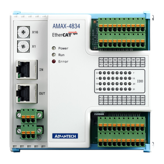
Figure 1.8 AMAX-4800 Appearance 1.4.2 LED Indicator System status and I/O indicators are located on the AMAX-4800 front panel. The LED indicator states follow EtherCAT specifications and are explained below. 1.4.2.1 LED States [Power] Indicator Indicator State System State Description Power Off The system power is turned off Power On... -
Page 18: Lan Connector
[Error] Indicator Indicator State Error Name Description No Error The device is in working condition Blinking Invalid Configuration General configuration error Slave device application has changed the EtherCAT state autonomously due to local error. Single Flash Local Error The error indicator bit is set to 1 in the AL Status register Double Flash Watchdog Timeout... -
Page 19: Rotate Switch
EEPROM. The master can be used to change EEPROM’s slave IDs. 1.4.5 Power AMAX-4800 series modules are equipped with two power input terminals, support an input power voltage of 10 ~ 30 V , and feature redundant power functionality. With the provision of two power sources, when one source is interrupted, the other source will assume the primary supply function immediately. - Page 20 AMAX-4800 User Manual...
-
Page 21: Chapter 2 Signal Connections
Chapter Signal Connections... -
Page 22: Overview
Maintaining signal connections is crucial to ensuring that the application system is sending and receiving data correctly. A good signal connection can reduce costly damage to hardware devices. This chapter provides useful information regarding connecting input and output signals to the AMAX-4800 series modules via an I/O connector. Signal Connections 2.2.1... -
Page 23: Amax-4830 Pin Assignment
2.2.3 AMAX-4830 Pin Assignment Signal Name Description I<0 ~ 15> Isolated digital input External common Vcc/GND for isolated digital input EC0, EC1 (8 channels share 1 EC pin) External ground for isolated digital input O<0 ~ 15> Isolated digital output Free wheeling common diode for isolated digital output PC0, PC1 (8 channels share 1 PC pin) -
Page 24: Amax-4834 Pin Assignment
2.2.5 AMAX-4834 Pin Assignment Signal Name Description O<0 ~ 31> Isolated digital output Free wheeling common diode for isolated digital output PC0, PC1, PC2, PC3 (8 channels share 1 PC pin) External ground for isolated digital output 2.2.6 AMAX-4850 Pin Assignment Signal Name Description I<0 ~ 15>... -
Page 25: Amax-4855 Pin Assignment
2.2.7 AMAX-4855 Pin Assignment Isolated Digital Input Relay Output Signal Name Description I<0 ~ 31> Isolated digital input External common Vcc/GND for isolated digital input EC0, EC1, EC2, EC3 (8 channels share 1 EC pin) External ground for isolated digital input NO<0 ~ 15>... -
Page 26: Amax-4856 Pin Assignment
2.2.8 AMAX-4856 Pin Assignment Isolated Digital Input Isolated Digital Output Signal Name Description I<0 ~ 31> Isolated digital input External common Vcc/GND for isolated digital input EC0, EC1, EC2, EC3 (8 channels share 1 EC pin) External ground for isolated digital input O<0 ~ 31>... -
Page 27: Amax-4860 Pin Assignment
2.2.9 AMAX-4860 Pin Assignment Signal Name Description I<0 ~ 7> Isolated digital input External common Vcc/GND for isolated digital input (8 channels share 1 EC pin) External ground for isolated digital inputs NO<0 ~ 7> Normally open pin of the relay output C<0 ~ 7>... -
Page 28: Connections
Connections 2.3.1 Isolated DI Connection All isolated digital input channels accept voltages ranging from 10 to 30 V. Additionally, every eight input channels share one external common pin (channels 0 ~ 7 use EC0, channels 8 ~ 15 use EC1). The figure below shows how to connect an external input source to the module’s isolated inputs. -
Page 29: Relay Output
2.3.3 Relay Output The figure below illustrates the structures and connections of the relay outputs. 2.3.4 Analog Input Connections AMAX-4817 provides eight differential analog input channels, as shown below. AMAX-4800 User Manual... -
Page 30: Analog Output Connections
2.3.5 Analog Output Connections AMAX-4820 provides four single-ended analog output channels. AMAX-4800 User Manual... -
Page 31: Chapter 3 Getting Started
Chapter Getting Started... -
Page 32: Introduction
Introduction This chapter explains how to access the AMAX-4800 module through the Advantech Common Motion utility. This utility provides a Windows-based application develop- ment environment for users to configure and verify AMAX-4800 function. The param- eter settings are easy to configure, shortening the system installation and evaluation time. -
Page 33: Master Page
Module Page If the EtherCAT slave is AMAX-4830, for example, the modules connected to the Advantech Common Motion utility will be shown in the slave tree node. Note! If more than one slave module is connected, each module must be assigned a unique slave ID. -
Page 34: Twincat
3.2.3.1 Digital Input/Output Modules AMAX-4830 supports 16 digital input channels and 16 digital output channels. To set the output/input value, left click the port value to access the Set Value pop-up menu. TwinCAT® TwinCAT software was developed by Beckhoff for operating EtherCAT devices. EtherCAT slave information (ESI) files must be imported to the TwinCAT folder for the AMAX-4800 module to function correctly. -
Page 35: Main Form
3.3.2 Main Form To start the TwinCAT System Manager software, right click the TwinCAT icon in the system tray and choose System Manager. 3.3.3 Install EtherCAT Driver Before initializing TwinCAT, the EtherCAT network interface card driver must be installed. Click on the Options menu and select the Show Real-Time Ethernet Com- patible Drivers option. -
Page 36: Scan For Amax-4800 Series Devices
3.3.4 Scan for AMAX-4800 Series Devices Select the I/O - Configuration -> I/O Devices menu item, then right click and select Scan Devices to initiate a scan for EtherCAT devices. Before scanning the devices, ensure that TwinCAT is in the Config mode. The current mode of the TwinCAT Sys- tem Manager is displayed at the lower right corner of the utility. - Page 37 Click [OK] when the HINT window appears. All network interface cards will be listed in the popup window. If slaves are connected to the network interface card and have been identified by TwinCAT, the device check box will be checked. Click [Yes] to scan for EtherCAT slave devices.
- Page 38 Click [Yes] to activate the slaves. After activation, AMAX-4800 will be listed as a slave device of the EtherCAT master and the “Run” status LED will emit a green light. This indicates that the user can begin operating the device. AMAX-4800 User Manual...
-
Page 39: Port Operation
3.3.5 Port Operation In the left window of the TwinCAT System Manager, right click on the branch to be configured. Digital Input/Output Modules For this example, an AMAX-4830 module is plugged into Slot 1 of AMAX-4830. There are 16 digital input channels and 16 digital output channels, and each port comprises 8 channels. -
Page 40: Codesys
CODESYS The CODESYS engineering tool is the standard widely implemented in OEM prod- ucts. The logic support and HMI integration makes CODESYS ideal for numerous applications, including machine automation, factory automation, building automation, and facility/infrastructure management. 3.4.1 Import ESI Files to CODESYS Open the CODESYS software: Select Tools ->... -
Page 41: How To Use The Amax-4800 Series With Codesys
3.4.2 How to Use the AMAX-4800 Series with CODESYS Master Page The slaves connected to the CODESYS system will be listed under the EtherCAT_Master menu item. The specifications of the AMAX-4800 module are shown in the right panel. Module Page If the EtherCAT slave is AMAX-4830, for example, the modules connected to the CODESYS utility will be shown in the slave tree node. -
Page 42: Module Configuration
I/O Mapping Variables There are 16 digital input and 16 digital output channels and the data type of each channel variable is in single bit. If the value is 1, this means that the channel is on; if the value is 0, this means that the channel is off. - Page 43 Analog Input Data (PDO) Index Name Data Type Flags Default 6000:01 AI 0 UINT16 RO P 0x0000 (0dec) 6000:02 AI 1 UINT16 RO P 0x0000 (0dec) 6000:03 AI 2 UINT16 RO P 0x0000 (0dec) 6000:04 AI 3 UINT16 RO P 0x0000 (0dec) 6000:05 AI 4...
-
Page 44: Amax-4820: 4-Channel Analog Output Module
Load/Save Calibration Parameters Index Name Data Type Flags Default 2190:01 Load Calibration Parameters UINT16 0x0000 (0dec) 1: Load calibration parameters from a user-configurable area 0: Load calibration parameters from the default area Index Name Data Type Flags Default 2190:02 Save Calibration Parameters UINT16 0x0000 (0dec) - Page 45 Analog Output Data (PDO) Index Name Data Type Flags Default 7000:01 AO 0 UINT16 RW P 0x0000 (0dec) 7000:02 AO 1 UINT16 RW P 0x0000 (0dec) 7000:03 AO 2 UINT16 RW P 0x0000 (0dec) 7000:04 AO 3 UINT16 RW P 0x0000 (0dec) For the 0 ~ 5 V range For the 0 ~ 10 V range...
- Page 46 Note! The offset calibration parameters are in 2's complement format. See the following table for further details. Code Value 0x7FFF +32767 0x7FFE +32766 0x0002 0x0001 0x0000 0xFFFF 0xFFFE 0x8001 -32767 0x8000 -32768 Load/Save Calibration Parameters Index Name Data Type Flags Default 2190:01...
-
Page 47: Amax-4830: 16-Channel Idi And 16-Channel Ido Module
3.5.2.3 Calibration Flow Disable the AO channel to be calibrated. Connect a DMM with a resolution of at least 6.5 bits to the AO channel. Set the range and enable the AO channel. Set AO data to 0x0040. If the reading of the DMM is outside the “Offset Value” range shown in the fol- lowing table, adjust the “AO n Offset Calibration Parameter”... -
Page 48: Amax-4833: 32-Channel Idi Module
Digital Output Data (PDO) Index Name Data Type Flags Default 7000:01 DO 0 BOOLEAN RW P FALSE 7000:02 DO 1 BOOLEAN RW P FALSE 7000:03 DO 2 BOOLEAN RW P FALSE 7000:04 DO 3 BOOLEAN RW P FALSE 7000:05 DO 4 BOOLEAN RW P... -
Page 49: Amax-4834: 32-Channel Ido Module
6002:06 DI 21 BOOLEAN RO P FALSE 6002:07 DI 22 BOOLEAN RO P FALSE 6002:08 DI 23 BOOLEAN RO P FALSE 6003:01 DI 24 BOOLEAN RO P FALSE 6003:02 DI 25 BOOLEAN RO P FALSE 6003:03 DI 26 BOOLEAN RO P FALSE 6003:04 DI 27... -
Page 50: Amax-4850: 16-Channel Idi And 8-Channel Photomos Output Module
7003:06 DO 29 BOOLEAN RW P FALSE 7003:07 DO 30 BOOLEAN RW P FALSE 7003:08 DO 31 BOOLEAN RW P FALSE TRUE: Turn ON the digital output channel. FALSE: Turn OFF the digital output channel. 3.5.6 AMAX-4850: 16-Channel IDI and 8-Channel PhotoMOS Output Module 3.5.6.1 Object Dictionary Configuration... -
Page 51: Amax-4855: 32-Channel Idi And 16-Channel Photomos Output Module
3.5.7 AMAX-4855: 32-Channel IDI and 16-Channel PhotoMOS Output Module 3.5.7.1 Object Dictionary Configuration Digital Input Data (PDO) Index Name Data Type Flags Default 6000:01 DI 0 BOOLEAN RO P FALSE 6000:02 DI 1 BOOLEAN RO P FALSE 6000:03 DI 2 BOOLEAN RO P FALSE... -
Page 52: Amax-4856: 32-Channel Idi And 32-Channel Ido Module
3.5.7.2 PhotoMOS Output Data (PDO) Index Name Data Type Flags Default 7000:01 DO 0 BOOLEAN RW P FALSE 7000:02 DO 1 BOOLEAN RW P FALSE 7000:03 DO 2 BOOLEAN RW P FALSE 7000:04 DO 3 BOOLEAN RW P FALSE 7000:05 DO 4 BOOLEAN RW P... - Page 53 6002:05 DI 20 BOOLEAN RO P FALSE 6002:06 DI 21 BOOLEAN RO P FALSE 6002:07 DI 22 BOOLEAN RO P FALSE 6002:08 DI 23 BOOLEAN RO P FALSE 6003:01 DI 24 BOOLEAN RO P FALSE 6003:02 DI 25 BOOLEAN RO P FALSE 6003:03 DI 26...
-
Page 54: Amax-4860: 8-Channel Idi And 8-Channel Relay Output Module
7003:07 DO 30 BOOLEAN RW P FALSE 7003:08 DO 31 BOOLEAN RW P FALSE TRUE: Turn ON the digital output channel. FALSE: Turn OFF the digital output channel. 3.5.9 AMAX-4860: 8-Channel IDI and 8-Channel Relay Output Module 3.5.9.1 Object Dictionary Configuration ... -
Page 55: Amax-4862: 16-Channel Idi And 16-Channel Relay Output Module
3.5.10 AMAX-4862: 16-Channel IDI and 16-Channel Relay Output Module 3.5.10.1 Object Dictionary Configuration Digital Input Data (PDO) Index Name Data Type Flags Default 6000:01 DI 0 BOOLEAN RO P FALSE 6000:02 DI 1 BOOLEAN RO P FALSE 6000:03 DI 2 BOOLEAN RO P FALSE... - Page 56 AMAX-4800 User Manual...
-
Page 57: Appendix A Object Dictionary
Appendix Object Dictionary... -
Page 58: Object Dictionary
Object Dictionary A.1.1 AMAX-4817 Object Dictionary Standard Object (0x1000-0x1FFF) Index 1000 Device Type Index Name Data Type Flags Default 1000:00 Device Type UInt32 M RO 0x00001389 (5001dec) Index 1001 Error Register Index Name Data Type Flags Default 1001:00 Error Register UInt16 0x0000 (0dec) Index 1008 Device Name... - Page 59 Index 1600 RxPDO Mapping Index Name Data Type Flags Default 1600:00 RxPDO Mapping 0 UInt8 0x01 (1dec) 1600:01 Dummy Output 0 UInt32 0x7000:01, 16 Index 1A00 TxPDO Mapping Index Name Data Type Flags Default 1A00:00 TxPDO Mapping 0 UInt8 0x08 (8dec) 1A00:01 AI 0 UInt32...
- Page 60 0x000186A0 1C32:05 Minimum Cycle Time UInt32 (100000dec) 1C32:06 Calc and Copy Time UInt32 0x00000000 (0dec) 1C32:08 Get Cycle Time UInt16 0x0000 (0dec) 1C32:09 Delay Time UInt32 0x00000000 (0dec) 1C32:0A Sync0 Cycle Time UInt32 0x00000000 (0dec) 1C32:0B SM-Event Missed UInt16 0x0000 (0dec) 1C32:0C Cycle Time Too Small UInt16...
- Page 61 Gain Calibration 2182:03 UInt16 0x8000 (32768dec) Parameter 2183:00 AI 3 Configuration UInt8 0x03 (3dec) 2183:01 Range UInt16 0x0000 (0dec) Offset Calibration 2183:02 UInt16 0x0000 (0dec) Parameter Gain Calibration 2183:03 UInt16 0x8000 (32768dec) Parameter 2184:00 AI 4 Configuration UInt8 0x03 (3dec) 2184:01 Range UInt16...
-
Page 62: Amax-4820 Object Dictionary
6000:03 AI 2 UInt16 RO P 0x0000 (0dec) 6000:04 AI 3 UInt16 RO P 0x0000 (0dec) 6000:05 AI 4 UInt16 RO P 0x0000 (0dec) 6000:06 AI 5 UInt16 RO P 0x0000 (0dec) 6000:07 AI 6 UInt16 RO P 0x0000 (0dec) 6000:08 AI 7 UInt16... - Page 63 Index 10F1 Error Settings Index Name Data Type Flags Default 10F1:00 Error Settings UInt8 0x02 (2dec) 10F1:01 Local Error Reaction UInt32 0x00000001 (1dec) 10F1:02 Sync Error Counter Limit UInt32 0x00000004 (4dec) Index 1600 RxPDO Mapping Index Name Data Type Flags Default 1600:00 RxPDO Mapping 0...
- Page 64 1C32:08 Get Cycle Time UInt16 0x0000 (0dec) 1C32:09 Delay Time UInt32 0x00000000 (0dec) 1C32:0A Sync0 Cycle Time UInt32 0x00000000 (0dec) 1C32:0B SM-Event Missed UInt16 0x0000 (0dec) 1C32:0C Cycle Time Too Small UInt16 0x0000 (0dec) 1C32:20 Sync Error BOOLEAN FALSE Index 1C33 SM Input Parameter Index Name Data Type...
-
Page 65: Amax-4830 Object Dictionary
2183:01 Range UInt16 0x0000 (0dec) Offset Calibration 2183:02 UInt16 0x0000 (0dec) Parameter Gain Calibration Param- 2183:03 UInt16 0x8000 (32768dec) eter Index 2190 Load/Save Calibration Parameter Index Name Data Type Flags Default Load/Save Calibration 2190:00 UInt8 0x02 (2dec) Parameter Load Calibration Param- 2190:01 UInt16 0x0000 (0dec) - Page 66 Index 100A Software Version Index Name Data Type Flags Default The firmware version of the 100A:00 Software Version String module Index 1018 Identity Object Index Name Data Type Flags Default 1018:00 Identity Object UInt16 0x0004 (4dec) 1018:01 Vendor ID UInt32 0x000013FE (5118dec) 1018:02 Product Code...
- Page 67 Index 1A00-1A01 TxPDO Mapping Index Name Data Type Flags Default 1A00:00 TxPDO Mapping 0 UInt8 0x08 (8dec) 1A00:01 UInt32 0x6000:01, 1 1A00:02 UInt32 0x6000:02, 1 1A00:03 UInt32 0x6000:03, 1 1A00:04 UInt32 0x6000:04, 1 1A00:05 UInt32 0x6000:05, 1 1A00:06 UInt32 0x6000:06, 1 1A00:07 UInt32 0x6000:07, 1...
- Page 68 Index Name Data Type Flags Default 1C32:00 SM Output Parameter UInt16 0x0020 (32dec) 1C32:01 Synchronization Type UInt16 0x0001 (1dec) 1C32:02 Cycle Time UInt32 Dependent Synchronization Types 1C32:04 UInt16 0x401E (16414dec) Supported 1C32:05 Minimum Cycle Time UInt32 0x000186A0 (100000dec) 1C32:06 Calc and Copy Time UInt32 0x00000000 (0dec) 1C32:08...
-
Page 69: Amax-4833 Object Dictionary
6001:02 BOOLEAN RO P FALSE 6001:03 DI10 BOOLEAN RO P FALSE 6001:04 DI11 BOOLEAN RO P FALSE 6001:05 DI12 BOOLEAN RO P FALSE 6001:06 DI13 BOOLEAN RO P FALSE 6001:07 DI14 BOOLEAN RO P FALSE 6001:08 DI15 BOOLEAN RO P FALSE Index 7000-7001 Digital Output Port Index... - Page 70 Index 1009 Hardware Version Index Name Data Type Flags Default The hardware version of the 1009:00 Hardware Version String module Index 100A Software Version Index Name Data Type Flags Default The firmware version of the 100A:00 Software Version String module Index 1018 Identity Object Index Name...
- Page 71 1A01:08 DI15 UInt32 0x6001:08, 1 1A02:00 TxPDO Mapping 2 UInt8 0x08 (8dec) 1A02:01 DI16 UInt32 0x6002:01, 1 1A02:02 DI17 UInt32 0x6002:02, 1 1A02:03 DI18 UInt32 0x6002:03, 1 1A02:04 DI19 UInt32 0x6002:04, 1 1A02:05 DI20 UInt32 0x6002:05, 1 1A02:06 DI21 UInt32 0x6002:06, 1 1A02:07 DI22...
- Page 72 Index 1C32 SM Output Parameter Index Name Data Type Flags Default 1C32:00 SM Output Parameter UInt16 0x0020 (32dec) 1C32:01 Synchronization Type UInt16 0x0001 (1dec) 1C32:02 Cycle Time UInt32 Dependent Synchronization Types 1C32:04 UInt16 0x401E (16414dec) Supported 1C32:05 Minimum Cycle Time UInt32 0x000186A0 (100000dec) 1C32:06...
-
Page 73: Amax-4834 Object Dictionary
6001:02 BOOLEAN RO P FALSE 6001:03 DI10 BOOLEAN RO P FALSE 6001:04 DI11 BOOLEAN RO P FALSE 6001:05 DI12 BOOLEAN RO P FALSE 6001:06 DI13 BOOLEAN RO P FALSE 6001:07 DI14 BOOLEAN RO P FALSE 6001:08 DI15 BOOLEAN RO P FALSE 6002:00 Digital Input Port 2... - Page 74 Index 1008 Device Name Index Name Data Type Flags Default 1008:00 Device Name String AMAX-4834 Index 1009 Hardware Version Index Name Data Type Flags Default The hardware version of 1009:00 Hardware Version String the module Index 100A Software Version Index Name Data Type Flags Default...
- Page 75 1601:05 DO12 UInt32 0x7001:05, 1 1601:06 DO13 UInt32 0x7001:06, 1 1601:07 DO14 UInt32 0x7001:07, 1 1601:08 DO15 UInt32 0x7001:08, 1 1602:00 RxPDO Mapping 2 UInt8 0x08 (8dec) 1602:01 DO16 UInt32 0x7002:01, 1 1602:02 DO17 UInt32 0x7002:02, 1 1602:03 DO18 UInt32 0x7002:03, 1 1602:04 DO19...
- Page 76 Index 1C32 SM Output Parameter Index Name Data Type Flags Default 1C32:00 SM Output Parameter UInt16 0x0020 (32dec) 1C32:01 Synchronization Type UInt16 0x0001 (1dec) 1C32:02 Cycle Time UInt32 Dependent Synchronization Types Sup- 1C32:04 UInt16 0x401E (16414dec) ported 0x000186A0 1C32:05 Minimum Cycle Time UInt32 (100000dec) 1C32:06...
-
Page 77: Amax-4850 Object Dictionary
7000:07 BOOLEAN RW P FALSE 7000:08 BOOLEAN RW P FALSE 7001:00 Digital Output Port 1 UInt8 RW P 0x08 (8dec) 7001:01 BOOLEAN RW P FALSE 7001:02 BOOLEAN RW P FALSE 7001:03 DO10 BOOLEAN RW P FALSE 7001:04 DO11 BOOLEAN RW P FALSE 7001:05 DO12... - Page 78 Index 1008 Device Name Index Name Data Type Flags Default 1008:00 Device Name String AMAX-4850 Index 1009 Hardware Version Index Name Data Type Flags Default The hardware version of the 1009:00 Hardware Version String module Index 100A Software Version Index Name Data Type Flags...
- Page 79 1A00:01 UInt32 0x6000:01, 1 1A00:02 UInt32 0x6000:02, 1 1A00:03 UInt32 0x6000:03, 1 1A00:04 UInt32 0x6000:04, 1 1A00:05 UInt32 0x6000:05, 1 1A00:06 UInt32 0x6000:06, 1 1A00:07 UInt32 0x6000:07, 1 1A00:08 UInt32 0x6000:08, 1 1A01:00 TxPDO Mapping 1 UInt8 0x08 (8dec) 1A01:01 UInt32 0x6001:01, 1 1A01:02...
- Page 80 Synchronization Types 1C32:04 UInt16 0x401E (16414dec) Supported 1C32:05 Minimum Cycle Time UInt32 0x000186A0 (100000dec) 1C32:06 Calc and Copy Time UInt32 0x00000000 (0dec) 1C32:08 Get Cycle Time UInt16 0x0000 (0dec) 1C32:09 Delay Time UInt32 0x00000000 (0dec) 1C32:0A Sync0 Cycle Time UInt32 0x00000000 (0dec) 1C32:0B SM-Event Missed...
-
Page 81: Amax-4855 Object Dictionary
6001:05 DI12 BOOLEAN RO P FALSE 6001:06 DI13 BOOLEAN RO P FALSE 6001:07 DI14 BOOLEAN RO P FALSE 6001:08 DI15 BOOLEAN RO P FALSE Index 7000 Digital Output Port Index Name Data Type Flags Default 7000:00 Digital Output Port 0 UInt8 RW P 0x08 (8dec) - Page 82 1018:01 Vendor ID UInt32 0x000013FE (5118dec) 1018:02 Product Code UInt32 0x00004855 (18517dec) 1018:03 Revision Number UInt32 0x00000000 (0dec) 1018:04 Serial Number UInt32 0x00000000 (0dec) Index 10F1 Error Settings Index Name Data Type Flags Default 10F1:00 Error Settings UInt8 0x02 (2dec) 10F1:01 Local Error Reaction UInt32...
- Page 83 1A01:01 UInt32 0x6001:01, 1 1A01:02 UInt32 0x6001:02, 1 1A01:03 DI10 UInt32 0x6001:03, 1 1A01:04 DI11 UInt32 0x6001:04, 1 1A01:05 DI12 UInt32 0x6001:05, 1 1A01:06 DI13 UInt32 0x6001:06, 1 1A01:07 DI14 UInt32 0x6001:07, 1 1A01:08 DI15 UInt32 0x6001:08, 1 1A02:00 TxPDO Mapping 2 UInt8 0x08 (8dec) 1A02:01...
- Page 84 Index 1C13 TxPDO Assignment Index Name Data Type Flags Default 1C13:00 TxPDO Assignment UInt16 0x0004 (4dec) 1C13:01 First Entry UInt16 0x1A00 (6656dec) 1C13:02 Second Entry UInt16 0x1A01 (6657dec) 1C13:03 Third Entry UInt16 0x1A02 (6658dec) 1C13:04 Fourth Entry UInt16 0x1A03 (6659dec) Index 1C32 SM Output Parameter Index Name...
- Page 85 Index 6000-6003 Digital Input Port Index Name Data Type Flags Default 6000:00 Digital Input Port 0 UInt8 RO P 0x08 (8dec) 6000:01 BOOLEAN RO P FALSE 6000:02 BOOLEAN RO P FALSE 6000:03 BOOLEAN RO P FALSE 6000:04 BOOLEAN RO P FALSE 6000:05 BOOLEAN...
-
Page 86: Amax-4856 Object Dictionary
7000:03 BOOLEAN RW P FALSE 7000:04 BOOLEAN RW P FALSE 7000:05 BOOLEAN RW P FALSE 7000:06 BOOLEAN RW P FALSE 7000:07 BOOLEAN RW P FALSE 7000:08 BOOLEAN RW P FALSE 7001:00 Digital Output Port 1 UInt8 RW P 0x08 (8dec) 7001:01 BOOLEAN RW P... - Page 87 1018:01 Vendor ID UInt32 0x000013FE (5118dec) 1018:02 Product Code UInt32 0x00004856 (18518dec) 1018:03 Revision Number UInt32 0x00000000 (0dec) 1018:04 Serial Number UInt32 0x00000000 (0dec) Index 10F1 Error Settings Index Name Data Type Flags Default 10F1:00 Error Settings UInt8 0x02 (2dec) 10F1:01 Local Error Reaction UInt32...
- Page 88 1603:04 DO27 UInt32 0x7003:04, 1 1603:05 DO28 UInt32 0x7003:05, 1 1603:06 DO29 UInt32 0x7003:06, 1 1603:07 DO30 UInt32 0x7003:07, 1 1603:08 DO31 UInt32 0x7003:08, 1 Index 1A00-1A03 TxPDO Mapping Index Name Data Type Flags Default 1A00:00 TxPDO Mapping 0 UInt8 0x08 (8dec) 1A00:01 UInt32...
- Page 89 Index 1C00 Sync Manager Type Index Name Data Type Flags Default 1C00:00 Sync Manager Type UInt16 0x0004 (4dec) Communication Type 1C00:01 UInt8 0x01 (1dec) Sync Manager 0 Communication Type 1C00:02 UInt8 0x02 (2dec) Sync Manager 1 Communication Type 1C00:03 UInt8 0x03 (3dec) Sync Manager 2 Communication Type...
- Page 90 Index 1C33 SM Input Parameter Index Name Data Type Flags Default 1C33:00 SM Input Parameter UInt16 0x0020 (32dec) 1C33:01 Synchronization Type UInt16 0x0001 (1dec) 1C33:02 Cycle Time UInt32 Dependent Synchronization Types 1C33:04 UInt16 0x401E (16414dec) Supported 1C33:05 Minimum Cycle Time UInt32 0x000186A0 (100000dec) 1C33:06...
- Page 91 6002:07 DI22 BOOLEAN RO P FALSE 6002:08 DI23 BOOLEAN RO P FALSE 6003:00 Digital Input Port 3 UInt8 RO P 0x08 (8dec) 6003:01 DI24 BOOLEAN RO P FALSE 6003:02 DI25 BOOLEAN RO P FALSE 6003:03 DI26 BOOLEAN RO P FALSE 6003:04 DI27 BOOLEAN...
-
Page 92: Amax-4860 Object Dictionary
7003:04 DO27 BOOLEAN RW P FALSE 7003:05 DO28 BOOLEAN RW P FALSE 7003:06 DO29 BOOLEAN RW P FALSE 7003:07 DO30 BOOLEAN RW P FALSE 7003:08 DO31 BOOLEAN RW P FALSE A.1.9 AMAX-4860 Object Dictionary A.1.9.1 Standard Object (0x1000-0x1FFF) Index 1000 Device Type Index Name Data Type... - Page 93 10F1:01 Local Error Reaction UInt32 0x00000001 (1dec) 10F1:02 Sync Error Counter Limit UInt32 0x00000004 (4dec) Index 1600 RxPDO Mapping Index Name Data Type Flags Default 1600:00 RxPDO Mapping 0 UInt8 0x08 (8dec) 1600:01 UInt32 0x7000:01, 1 1600:02 UInt32 0x7000:02, 1 1600:03 UInt32 0x7000:03, 1...
- Page 94 Index 1C13 TxPDO Assignment Index Name Data Type Flags Default 1C13:00 TxPDO Assignment UInt16 0x0001 (1dec) 1C13:01 First Entry UInt16 0x1A00 (6656dec) Index 1C32 SM Output Parameter Index Name Data Type Flags Default 1C32:00 SM Output Parameter UInt16 0x0020 (32dec) 1C32:01 Synchronization Type UInt16...
-
Page 95: Amax-4862 Object Dictionary
6000:05 BOOLEAN RO P FALSE 6000:06 BOOLEAN RO P FALSE 6000:07 BOOLEAN RO P FALSE 6000:08 BOOLEAN RO P FALSE Index 7000 Digital Output Port Index Name Data Type Flags Default 7000:00 Digital Output Port 0 UInt8 RW P 0x08 (8dec) 7000:01 BOOLEAN RW P... - Page 96 1018:01 Vendor ID UInt32 0x000013FE (5118dec) 1018:02 Product Code UInt32 0x00004862 (18530dec) 1018:03 Revision Number UInt32 0x00000000 (0dec) 1018:04 Serial Number UInt32 0x00000000 (0dec) Index 10F1 Error Settings Index Name Data Type Flags Default 10F1:00 Error Settings UInt8 0x02 (2dec) 10F1:01 Local Error Reaction UInt32...
- Page 97 1A01:01 UInt32 0x6001:01, 1 1A01:02 UInt32 0x6001:02, 1 1A01:03 DI10 UInt32 0x6001:03, 1 1A01:04 DI11 UInt32 0x6001:04, 1 1A01:05 DI12 UInt32 0x6001:05, 1 1A01:06 DI13 UInt32 0x6001:06, 1 1A01:07 DI14 UInt32 0x6001:07, 1 1A01:08 DI15 UInt32 0x6001:08, 1 Index 1C00 Sync Manager Type Index Name Data Type...
- Page 98 1C32:0C Cycle Time Too Small UInt16 0x0000 (0dec) 1C32:20 Sync Error BOOLEAN FALSE Index 1C33 SM Input Parameter Index Name Data Type Flags Default 1C33:00 SM Input Parameter UInt16 0x0020 (32dec) 1C33:01 Synchronization Type UInt16 0x0001 (1dec) 1C33:02 Cycle Time UInt32 Dependent Synchronization Types...
- Page 99 Index 7000-7001 Digital Output Port Index Name Data Type Flags Default 7000:00 Digital Output Port 0 UInt8 RW P 0x08 (8dec) 7000:01 BOOLEAN RW P FALSE 7000:02 BOOLEAN RW P FALSE 7000:03 BOOLEAN RW P FALSE 7000:04 BOOLEAN RW P FALSE 7000:05 BOOLEAN...
- Page 100 AMAX-4800 User Manual...
- Page 101 AMAX-4800 User Manual...
- Page 102 No part of this publication may be reproduced in any form or by any means, such as electronically, by photocopying, recording, or otherwise, without prior written permission from the publisher. All brand and product names are trademarks or registered trademarks of their respective companies. © Advantech Co., Ltd. 2018...
Need help?
Do you have a question about the AMAX-4800 Series and is the answer not in the manual?
Questions and answers