Pfeiffer Vacuum HISCROLL 6 Operating Instructions Manual
Scroll pump with integrated pressure sensor
Hide thumbs
Also See for HISCROLL 6:
- Translation of the original (66 pages) ,
- Operating instructions manual (84 pages) ,
- Operating instructions manual (160 pages)

Related Manuals for Pfeiffer Vacuum HISCROLL 6


Summary of Contents for Pfeiffer Vacuum HISCROLL 6
- Page 1 OPERATING INSTRUCTIONS Translation of the Original HISCROLL 6 | 12 | 18 Scroll pump with integrated pressure sensor...
-
Page 2: Telegram Example
Dear Customer, Thank you for choosing a Pfeiffer Vacuum product. Your new scroll pump is designed to support you with its performance, perfect operation and without impacting your individual application. The name Pfeiffer Vacuum stands for high-quality vacuum technology, a comprehensive and complete range of top-quality products and first-class service. -
Page 3: Table Of Contents
Limits of use of the product Proper use Foreseeable improper use Personnel qualification 2.7.1 Ensuring personnel qualification 2.7.2 Personnel qualification for maintenance and repair 2.7.3 Advanced training with Pfeiffer Vacuum Product description Function 3.1.1 Drive 3.1.2 Cooling 3.1.3 Shaft bearing 3.1.4 Gas ballast... - Page 4 Reference value inputs Operation Putting the vacuum pump into operation Switch vacuum pump on Configuring the connections with the Pfeiffer Vacuum parameter set 8.3.1 Configuring the digital outputs 8.3.2 Configuring the digital input 8.3.3 Selecting the interfaces 8.3.4 Configuring accessories...
- Page 5 Table of contents Service solutions by Pfeiffer Vacuum Spare parts Accessories 15.1 Accessory information 15.2 Ordering accessories Technical data and dimensions 16.1 General 16.2 Technical data 16.3 Substances in contact with the media 16.4 Dimensions Declaration of Conformity UK Declaration of Conformity...
- Page 6 Accessories for HiScroll Tbl. 26: Conversion table: Pressure units Tbl. 27: Conversion table: Units for gas throughput Tbl. 28: Technical data for HiScroll 6 Tbl. 29: Technical data for HiScroll 12 Tbl. 30: Technical data for HiScroll 18 Tbl. 31:...
- Page 7 Tip seal nut in the spiral housing Fig. 30: Assembling the housing parts Fig. 31: HiScroll maintenance kit 1 Fig. 32: HiScroll valve set Fig. 33: HiScroll 6 | Version with pressure sensor Fig. 34: HiScroll 12 | HiScroll 18 | Version with pressure sensor 7/80...
-
Page 8: About This Manual
Keep the manual for future consultation. 1.1 Validity This operating instructions is a customer document of Pfeiffer Vacuum. The operating instructions de- scribe the functions of the named product and provide the most important information for the safe use of the device. The description is written in accordance with the valid directives. The information in this op- erating instructions refers to the product's current development status. -
Page 9: Instructions In The Text
The rating plate is located clearly visible on a longitudinal side of D-35614 Asslar Berliner Str. 43 the vacuum pump. Mod. HiScroll 6 P/N PD S10 010 S/N - - - - - - - - ) max. 6.1 m Mass 19 kg TÜV Rheinland... -
Page 10: Fig. 1: Position Of The Stickers On The Product
About this manual Rating plate The rating plate is located clearly visible on a longitudinal side of D-35614 Asslar Berliner Str. 43 the vacuum pump. Mod. HiScroll 18 P/N PD S30 010 S/N - - - - - - - - ) max. -
Page 11: Abbreviations
About this manual 1.3.4 Abbreviations Abbreviation Explanation Atmospheric pressure Operating instructions Rotation speed value of a vacuum pump (frequency, in rpm or Hz) Fluorinated rubber Gas ballast High vacuum [P:xxx] Parameters are printed in bold as three-digit numbers in square brackets. Example: [P:xxx] Software version Personal computer PTFE... -
Page 12: Safety
Safety 2 Safety 2.1 General safety information The following 4 risk levels and 1 information level are taken into account in this document. DANGER Immediately pending danger Indicates an immediately pending danger that will result in death or serious injury if not observed. ►... - Page 13 Safety Risks during installation DANGER Danger to life from electric shock Inadequate or incorrect grounding of the unit leads to contact-sensitive voltage on the housing. When making contact, increased leakage currents will cause a life-threatening electric shock. ► Before the installation, check that the connection leads are voltage-free. ►...
- Page 14 Safety CAUTION Danger of injury from bursting as a result of high pressure in the exhaust line Faulty or inadequate exhaust pipes lead to dangerous situations, e.g., increased exhaust pressure. There is a danger of bursting. Injuries caused by flying fragments, the escaping of high pressure, and damage to the unit cannot be excluded.
- Page 15 Safety CAUTION Danger of injury from bursting as a result of high pressure in the exhaust line Faulty or inadequate exhaust pipes lead to dangerous situations, e.g., increased exhaust pressure. There is a danger of bursting. Injuries caused by flying fragments, the escaping of high pressure, and damage to the unit cannot be excluded.
-
Page 16: Safety Precautions
Safety Risks in the event of malfunctions WARNING Danger to life from electric shock in the event of a fault In the event of a fault, devices connected to the mains may be live. There is a danger to life from electric shock when making contact with live components. -
Page 17: Proper Use
The work described in this document may only be carried out by persons who have appropriate profes- sional qualifications and the necessary experience or who have completed the necessary training as provided by Pfeiffer Vacuum. Training people 1. Train the technical personnel on the product. -
Page 18: Ensuring Personnel Qualification
─ Customer with Pfeiffer Vacuum service training ─ Pfeiffer Vacuum service technician 2.7.3 Advanced training with Pfeiffer Vacuum For optimal and trouble-free use of this product, Pfeiffer Vacuum offers a comprehensive range of courses and technical trainings. For more information, please contact Pfeiffer Vacuum technical training. -
Page 19: Product Description
3 Product description 3.1 Function The Pfeiffer Vacuum scroll pump is a vacuum pump operating dry in a suction chamber for generating a coarse or medium vacuum according to the physical pumping principle of a spiral vacuum pump. The pump is equipped with an integrated drive and control unit. A three-stage gas ballast system supports the prevention of condensation accumulating in the vacuum pump. -
Page 20: Drive
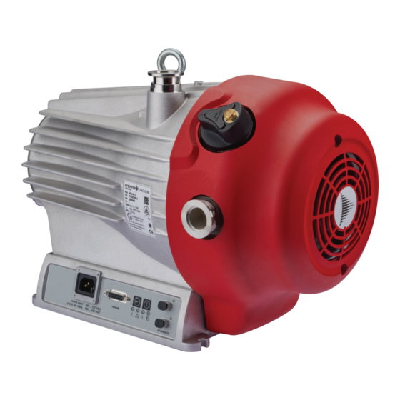
Product description Fig. 3: HiScroll design, version with pressure sensor 1 Protective cover for DN 25 vacuum connection Accessory connection "C" 2 Eye bolt Accessory connection "D" 3 Dummy cover for version without GB "Remote" connecting socket 4 Fan cover Electronic drive unit 5 Vacuum connection Base with fixing hole... -
Page 21: Connections
Interfaces of the electronic drive unit 3.3 Identifying the product ► To ensure clear identification of the product when communicating with Pfeiffer Vacuum, always keep all of the information on the rating plate to hand. ► Learn about certifications through test seals on the product or at www.certipedia.com... -
Page 22: Transportation And Storage
Transportation and Storage 4 Transportation and Storage 4.1 Transporting vacuum pump WARNING Risk of serious injury from swinging, toppling or falling objects During transport, there is a risk of crushing and impact on swinging, toppling or falling objects. There is a risk of injuries to limbs, up to and including bone fractures and head injuries. ►... -
Page 23: Storing The Vacuum Pump
Transportation and Storage Transporting the vacuum pump without its packaging 1 eye bolt is included in the scope of delivery. It is securely bolted to the vacuum pump at the factory. 1. Attach suitable lifting tools to the eye bolt. 2. -
Page 24: Installation
– Observe any pumping speed decrease. Preventing throttling losses Using short vacuum lines with a large nominal diameter prevents throttling losses. Condensate separator Pfeiffer Vacuum recommends the installation of a condensate separator in case vapors are formed from moisture during evacuation. 24/80... -
Page 25: Connecting The Exhaust Side
► Observe the permissible pressures and pressure differentials for the product. ► Check the function of the exhaust line on a regular basis. Condensate separator Pfeiffer Vacuum recommends installing a condensate separator, with condensate drain at the lowest point of the exhaust line. 25/80... -
Page 26: Connecting Gas Ballast External Supply
The gas ballast system of the scroll pump is suitable for being connected to a gas external supply. Cou- plings for the G 1/8" connection from the Pfeiffer Vacuum accessories range are available for this pur- pose. -
Page 27: Connecting To Mains Power Supply
Installation Fig. 8: Connecting gas ballast external supply 1 Sinter filter Gas ballast connection opening 2 Gas ballast valve External gas supply line 3 Example of connecting coupling External gas supply Connecting gas supply 1. Turn the gas ballast valve to position “0”. 2. -
Page 28: Fig. 9: Connecting To Mains Power Supply
The electronic drive unit starts when the mains supply is established. Establishing mains supply 1. Order a country-specific power cable from the Pfeiffer Vacuum accessories. 2. Always ensure a secure connection to the earthed conductor. 3. Plug the mains cable into the connecting plug of the electronic drive unit. -
Page 29: Interfaces
The 15-pin sub-D connection with the "remote" designation offers the possibility to operate the electron- ic drive unit via remote control. The following specifications are the factory settings for the electronic drive unit. They can be configured with the Pfeiffer Vacuum parameter set. ► Utilize the screened plug and cable. -
Page 30: Inputs
6.2.2 Outputs The digital outputs at the "remote" connection have a maximum load limit of 24 V/50 mA per output. You can configure all listed outputs with the Pfeiffer Vacuum parameter set via the RS-485 interface (description relates to factory settings). -
Page 31: Rs-485
DO2/Pin 9 Active high 6.2.3 RS-485 Connecting RS-485 via D-Sub ► Connect a Pfeiffer Vacuum control unit or an external PC via pin 13 and pin 14 at the D-Sub con- nection of the electronic drive unit. 6.3 Connecting control unit Fig. 12: Connecting a control unit via the "remote"... -
Page 32: Pfeiffer Vacuum Protocol For Rs-485 Interface
3. Connect all devices with RS-485 D+ and RS-485 D- to the bus. 6.5 Pfeiffer Vacuum protocol for RS-485 interface 6.5.1 Telegram frame The telegram frame of the Pfeiffer Vacuum protocol contains only ASCII code characters [32; 127], the exception being the end character of the telegram C . Basically, a master (e.g. -
Page 33: Telegram Description
Interfaces 6.5.2 Telegram description Data query --> Control command --> Data response / Control command understood --> Error message --> NO_DEF Parameter number n2–n0 no longer exists _RANGE Data dn–d0 outside the permissible range _LOGIC Logical access error 6.5.3 Telegram example 1 Data query Current rotation speed (parameter [P:309], device address slave: "123") -->... -
Page 34: Data Types
Interfaces 6.5.5 Data types Data type Description Length Example l1 – l0 boolean_old Logical value (false/true) 000000 is equivalent to false 111111 is equivalent to true u_integer Positive whole number 000000 to 999999 u_real Positive fixed point number 001571 corresponds with 15.71 string Any character string with 6 charac-... -
Page 35: Parameter Set
Important settings and function-related characteristics are factory-programmed into the electronic drive unit as parameters. Each parameter has a three-digit number and a description. The use of the parame- ter is possible via Pfeiffer Vacuum displays and control panels, or externally via RS-485 using Pfeiffer Vacuum protocol. - Page 36 Parameter set Display Designations Functions Data Unit min. max. type cess fault type PressMode Pressure regu- 0 = off lation 1 = on Cfg DO1 Output DO1 0 = Switch-point reached configuration 1 = No error 2 = Error 5 = Set rotation speed reached 6 = Pump on 9 = Always "0"...
-
Page 37: Status Requests
Parameter set 7.3 Status requests Display Designations Func- Data Access Unit min. max. tions type type fault RemotePrio Remote priority 0 = no 1 = yes Error code Error code OvTempElec Excess temperature drive 0 = no electronics 1 = yes OvTempPump Excess temperature pump 0 = no... - Page 38 Parameter set Display Designations Func- Data Access Unit min. max. tions type type fault PrsCorrPi 1 Correction factor 1 RS485Adr RS-485 Interface address Tbl. 10: Reference value inputs 38/80...
-
Page 39: Operation
Important settings and function-related variables are programmed ex factory as parameters in the vac- uum pump electronic drive unit. Each parameter has a three-digit number and a description. Parameter- driven operation and control is supported via Pfeiffer Vacuum displays and control units, or externally via RS-485 using Pfeiffer Vacuum protocol. -
Page 40: Configuring The Digital Input
Operation Option Description 9 = Always "0" GND for the control of an external device 10 = Always "1" +24 V DC for the control of an external device 11 = Remote priority active active, if the remote priority is active 21 = Gas ballast valve, delayed +24 V DC with a time delay after pumping station on, only in version with gas ballast valve... -
Page 41: Selecting Operating Mode
Operation Fig. 14: Accessory connector assignment 1 + 5 V (blue) + 24 V (depending on software configuration) 2 Sensor RxD / master TxD (white) GND (black) 3 Sensor TxD / master RxD (green) Configuring accessories ► Configure connected accessories with parameters [P:068] and [P:069], if necessary. –... -
Page 42: Normal Operation
3. Check the set rotation speed (parameter [P:308] or [P:397]). 8.5.2 Standby mode Pfeiffer Vacuum recommends standby mode for during process and production stops. When standby mode is active, the electronic drive unit reduces the rotation speed of the vacuum pump. The factory setting is 50 % of the nominal rotation speed. -
Page 43: Auto Boost
Operation Permissible rotation speed range Settings in the rotation speed mode or stand-by mode are subject to the permissible rota- tion speed range of the respective vacuum pump (technical data). The electronic drive unit adjusts the set rotation speed automatically to the next valid value. Set the rotation speed setting mode 1. -
Page 44: Determining Effective Pressure With Calibration Factors
Operation 8.7 Determining effective pressure with calibration factors Gas and vapor mixtures Process gases are mostly mixtures of gas and vapor. Precise measuring of gas and vapor mixtures is only possible using partial pressure measurement instruments, for example a quadrupole mass spectrometer. The measurement signal of the pressure sensor depends on the type of gas in the Pirani range. -
Page 45: Operation With Gas Ballast
Operation p [hPa] Freon 12 –1 Water vapor –2 –3 –3 –2 –1 [hPa] Fig. 16: Displayed pressure Within the pressure range < 1 hPa, the display is linear. Set calibration factor at electronic drive unit ► Use [P:742] to enter calibration factor and correct displayed measured value. Alternatively: Calculating pressure for gases other than air 1. -
Page 46: Controlling Gas Ballast Valve With A Pressure Sensor
Operation NOTICE Risk of damage from condensation in vacuum pump Exceeding the saturation vapor pressure of process media during the compression phase leads to condensation in the suction chamber. This results in an increase of the achievable ultimate pressure and to a general deterioration of the performance data of the vacuum pump as a whole. Corrosion and contamination impair service life. -
Page 47: Controlling Gas Ballast Valve Without A Pressure Sensor
Operation RS-485 RS-485 RS-485 RS-485 Ventilsteuerung [P052] [P030] [P740] [P010] GB-Ventil Ventilmodus Druckwert HiScroll ein/aus permanent [deaktiviert] geschlossen permanent offen > 3 mbar geschlossen < 3 mbar [gültig] [aktiviert] [ein] [auto] [P:721] permanent [geschlossen] geschlossen permanent offen [offen] Fig. 17: Pressure-dependent gas ballast valve control in automatic mode Procedure ►... -
Page 48: Operating Mode Display Via Led
8.9 Operating mode display via LED LEDs on the electronic drive unit show the basic operating states of the vacuum pump. A differentiated error and warning display is only possible for operation with the Pfeiffer Vacuum display and control unit or a PC. -
Page 49: Maintenance
► Disconnect the mains cable from the vacuum pump. NOTICE Danger of property damage from improper maintenance Unprofessional work on the vacuum pump will lead to damage for which Pfeiffer Vacuum accepts no liability. ► We recommend taking advantage of our service training offering. -
Page 50: Replacing The Non-Return Valve On The Exhaust Side
We recommend that Pfeiffer Vacuum Service (PV) carry out maintenance work at level 3. Pfeiffer Vacuum will be released from all warranty and liability claims if maintenance work is not carried out properly. This also applies wherever parts other than original spare parts are used. -
Page 51: Removing The Non-Return Valve
Maintenance 9.3.1 Removing the non-return valve Fig. 19: Removing valve 1 Spiral housing Compression spring 2 O-ring Valve guide 3 Valve plate Removing valve 1. Use the face spanner to unscrew the valve guide with compression spring and valve plate from the spiral housing. -
Page 52: Replacing The Gas Ballast Valve
Maintenance 9.4 Replacing the gas ballast valve Prerequisites ● Vacuum pump switched off ● Vacuum system vented to atmospheric pressure ● Electrical supply disconnected ● Mains cable disconnected ● Vacuum inlet sealed with the original protective cover Required tools ● Slot screwdriver ●... -
Page 53: Installing Gas Ballast Valve
Maintenance Fig. 22: Removing gas ballast valve 1 Cylinder screw, 3x Compression spring 2 Gas ballast handle O-ring 3 Valve plate Base plate 4 Weight Removing gas ballast valve 1. Unscrew the cylinder screws from the gas ballast handle. 2. Remove the gas ballast handle from the base plate. 3. -
Page 54: Changing The Tip Seal
Maintenance Fig. 24: Installing gas ballast valve 1 O-ring, 3x Sinter filter 2 Gas ballast valve Ball 3 Special screw Spiral housing 4 Cover Installing gas ballast valve 1. Insert the O-rings into the designated grooves in the spiral housing. 2. -
Page 55: Fig. 25: Loosening The Fan Cover On The Scroll Pump
Maintenance Fig. 25: Loosening the fan cover on the scroll pump 1 Gas ballast valve Hexagon socket screw 2 Fan cover Exhaust connection without protective cap 3 Washer Accessory connection Loosening the fan cover 1. Remove any power supply plugs from the accessory connections (e.g., pressure sensor). 2. -
Page 56: Replacing The Tip Seal
Maintenance Fig. 27: Removing the scroll pump spiral housing 1 Hexagon socket screw (5×) Pump housing 2 Washer (5×) Hexagon socket screw as an auxiliary hole 3 Spiral housing Bottom auxiliary hole 4 Top auxiliary hole Removing the spiral housing 1. -
Page 57: Fig. 28: Replacing The Tip Seal On The Scroll Pump
Maintenance Fig. 28: Replacing the tip seal on the scroll pump 1 Tip seal Tip seal 2 Orbiter O-ring 3 Pump housing Spiral housing Removing the tip seal 1. Place the pump housing in an upright position. 2. Use the o-ring picker and remove the o-ring from the spiral housing. 3. -
Page 58: Assembling The Pump Housing
Maintenance 3. Moisten the groove of the spiral housing with a little isopropanol as an assembly aid for the o-ring. 4. Carefully insert the o-ring into the spiral housing. 9.5.3 Assembling the pump housing Required tools ● Allen key, WAF 5 ●... -
Page 59: Final Inspection
Maintenance 4. Secure the fan housing with both hexagon socket screws and washers. – Tightening torque: 3.5 Nm 5. Optional: Fasten an existing mating plug on the “remote” connection of the electronic drive unit. – Tightening torque: 0.4 Nm 9.6 Final inspection Prerequisite ●... -
Page 60: Decommissioning
1. Clean the vacuum pump exterior with a lint-free cloth and a little isopropanol. 2. If necessary, arrange for Pfeiffer Vacuum Service to completely clean the vacuum pump. 3. Observe the total running time of the vacuum pump and if necessary, use support services of Pfeiffer Vacuum. -
Page 61: Recycling And Disposal
– Fluoroelastomers (FKM) – Potentially contaminated components that come into contact with media 11.2 Disposing of the scroll pump Pfeiffer Vacuum scroll pumps contain materials which must be recycled. 1. Disconnect the electronic drive unit. 2. Dismantle the motor. 3. Decontaminate the components that come into contact with process gases. -
Page 62: Malfunctions
● Incorrect operating volt- ● Supply the correct operating voltage. ● Electronic drive unit de- ● Contact Pfeiffer Vacuum Service. fective The vacuum pump fails to reach ● Leakage on the vacuum 1. Carry out leak detection. -
Page 63: Error Codes
1. Read out error codes via Pfeiffer display and control units or a PC. 2. Remove the cause of the malfunction. 3. Reset the malfunction message with parameter [P:009]. – Use preconfigured quick keys with the symbol or display tiles on Pfeiffer Vacuum display and control units. Error Problem... -
Page 64: Warning And Malfunction Messages When Operating With Control Units
Malfunctions Error Problem Possible causes Remedy code Err098 Internal communication er- – ● Contact Pfeiffer Vacuum Service Err114 Final stage temperature – ● Contact Pfeiffer Vacuum Service evaluation faulty Err118 Excess temperature, final ● Insufficient ● Check to make sure the fan is working. - Page 65 ● Replace the pressure gauge com- pletely ** Error E040 ** Hardware error ● external RAM faulty ● Contact Pfeiffer Vacuum Service ** Error E042 ** Hardware error ● EPROM checksum incorrect ● Contact Pfeiffer Vacuum Service ** Error E043 ** Hardware error ●...
-
Page 66: Service Solutions By Pfeiffer Vacuum
We are always focused on perfecting our core competence – servicing of vacuum components. Once you have purchased a product from Pfeiffer Vacuum, our service is far from over. This is often exactly where service begins. Obviously, in proven Pfeiffer Vacuum quality. - Page 67 Service solutions by Pfeiffer Vacuum 5. Prepare the product for transport in accordance with the provisions in the contamination declaration. a) Neutralize the product with nitrogen or dry air. b) Seal all openings with blind flanges, so that they are airtight.
-
Page 68: Spare Parts
Fig. 31: HiScroll maintenance kit 1 1 Tip seal O-ring Spare part package Order number HiScroll 6 HiScroll 12 | HiScroll 18 Maintenance kit 1 – maintenance level 1 PD E10 000 -T PD E20 000 -T Tbl. 23: Spare part package... -
Page 69: Tbl. 24: Spare Part Package
O-ring, 19 × 2.5 2 Compression spring, 2× O-ring, 6 × 3 3 O-ring, 16 × 1.5 Spare part package Order number HiScroll 6 | HiScroll 12 | HiScroll 18 Valve set PD E13 000 -T Tbl. 24: Spare part package 69/80... -
Page 70: Accessories
Accessories 15 Accessories 15.1 Accessory information Display units Display and operating units are used to check and adjust operating parameters. Cable and adapter Mains, interface, connection, and extension cables provide a secure and suitable connection. Different lengths on request Integrated pressure measurement Evaluation and control by the integrated electronic drive unit, independently of an additional power sup- Condensate separator Protect the vacuum pump against fluids from the intake line and from the condensate return from the... -
Page 71: Tbl. 25: Accessories For Hiscroll
Accessories Article Order number RJ 45 interface cable on M12 for HiPace PM 051 726 -T USB RS-485 converter PM 061 207 -T Tbl. 25: Accessories for HiScroll 71/80... -
Page 72: Technical Data And Dimensions
Technical data and dimensions 16 Technical data and dimensions 16.1 General Basis for the technical data of Pfeiffer Vacuum spiral vacuum pumps: ● Specifications according to PNEUROP committee PN5 ● ISO 21360-1 2016: “Vacuum technology - Standard methods for measuring vacuum-pump per- formance - Part 1: General description”... - Page 73 Pa m³/s 5 · 10 Pa m³/s Weight 19 kg 19 kg 19 kg Tbl. 28: Technical data for HiScroll 6 Selection field HiScroll 12, scroll HiScroll 12, scroll HiScroll 12, scroll pump, incl. pressure pump, with pres- pump, with pressure...
- Page 74 Technical data and dimensions Selection field HiScroll 12, scroll HiScroll 12, scroll HiScroll 12, scroll pump, incl. pressure pump, with pres- pump, with pressure sensor sure sensor, with- sensor and automat- out GB ed GB I/O interfaces RS-485 RS-485 RS-485 Emission sound pressure 47 dB(A) 47 dB(A)
-
Page 75: Substances In Contact With The Media
Technical data and dimensions Selection field HiScroll 18, scroll HiScroll 18, scroll HiScroll 18, scroll pump, incl. pressure pump, with pressure pump, with pressure sensor sensor, without GB sensor and automat- ed GB Integral leakage rate 5 · 10 Pa m³/s 5 ·... -
Page 76: Dimensions
2 0 .5 2 6 0 4× Gummifüße/ rubber feet 1 1 4 DN 25 ISO-KF 2 9 8 2 0 7 .5 3 8 0 2 0 0 Fig. 33: HiScroll 6 | Version with pressure sensor Dimensions in mm 76/80... - Page 77 Technical data and dimensions 30.5 (4x) Gummifüße rubber feet DN 25 ISO-KF Fig. 34: HiScroll 12 | HiScroll 18 | Version with pressure sensor Dimensions in mm 77/80...
-
Page 78: Declaration Of Conformity
Semi S8 0218 EN 61000-3-2: 2019 DIN EN 63000: 2019 The authorized representative for the compilation of technical documents is Dr. Adrian Wirth, Pfeiffer Vacuum GmbH, Berliner Straße 43, 35614 Asslar, Germany. Signature: Pfeiffer Vacuum GmbH Berliner Straße 43 35614 Asslar Germany (Daniel Sälzer) -
Page 79: Declaration Of Conformity
IEC 61000-3-2: 2018 Semi S8 0218 IEC 63000: 2016 The importer into the United Kingdom and the authorized representative for the compilation of technical documentation is Pfeiffer Vacuum Ltd, 16 Plover Close, Interchange Park, MK169PS Newport Pagnell. Signature: Pfeiffer Vacuum GmbH Berliner Straße 43...
Need help?
Do you have a question about the HISCROLL 6 and is the answer not in the manual?
Questions and answers